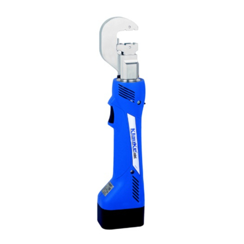
Klauke EK 60UNV-L User manual

EK 60UNV-L
D Bedienungsanleitung
GB Instruction Manual
F Mode d´emploi
RUS Инструкция по
эксплуатации
Anzahl der Seiten: YY
HE.13423_B © 09/2010 TE-2
Verbindungen mit System
The Power of Partnership
Gustav Klauke GmbH • Auf dem Knapp 46 • D-42855 Remscheid
Telefon ++49 +2191-907-0 • Telefax ++49 +2191-907-141 • www.klauke.textron.com
Serialnummer

EK 60UNV-L
I
Bedienungsanleitung/Instruction Manual
BL1830 (RAL2) 2
optional:
NG2
HE.15333
HE.13423_B © 09/2010
L1830
(
RAL2
)
2
o
p
tional
:
NG2
5
4
31
98 10
Bild/pic./fig. 1 (siehe/see Tab. 3)
6
7
2K
z.B.

EK 60UNV-L
II
Bedienungsanleitung/Instruction Manual
5304711CV142 batch# e.g. 304711
datecode e.g. „-cv“ for year 2009, month July
consecutive# e.g. „142“ for the 142nd tool
datecode
Year Code Month Code Month Code
2007 A Jan. N July V
2008 B Feb. P Aug. W
2009 C Mar. Q Sept. X
2010 D Apr. R Oct. Y
2011 E May S Nov. Z
2012 F June T Dec. 1
1 2 3 4
D-42855
Remscheid
5
Bild/pic./fig. 3 Bild/pic./fig. 4
(BL1830) 22 min.
RAL2
10 - 40°C
CLICK
Bild/pic./fig. 5 Bild/pic./fig. 7 Bild/pic./fig. 9Bild/pic./fig. 6 Bild/pic./fig. 8
Bild/pic./fig. 10
Li-ion
Bild/pic./fig. 11
®
#884676B996
#884598C990
Bild/pic./fig. 12
1. 2.3.
1. 2.3.
Bild/pic./fig. 13
OIL
1. 2.
3.
HE.13423_B © 09/2010
HE.13420
HE.13422
EK 60UNV-L
Nennspannung (Voltage): 18V DC
Antriebskraft (Driving Force): 60 kN
HE.13421
Bild/pic./fig. 2

EK 60UNV-L
III
Bedienungsanleitung/Instruction Manual
Bild/pic./fig. 15
Bild/pic./fig. 16 Bild/pic./fig. 17
Bild/pic./fig. 18 Bild/pic./fig. 19
CLICK
330°
Bild/pic./fig. 14
Bild/pic./fig. 20 Bild/pic./fig. 21
siehe Bild/pic./fig. 27
HE.13423_B © 09/2010
1.
2.

EK 60UNV-L
IV
Bedienungsanleitung/Instruction Manual
Bild/pic./fig. 25
Bild/pic./fig. 22 Bild/pic./fig. 23
siehe Bild/pic./fig. 31
siehe Bild/pic./fig. 29, 33
siehe Bild/pic./fig. 26, 28, 30
siehe Bild/pic./fig. 32
Bild/pic./fig. 24
1.
2.
HE.13423_B © 09/2010
1.
2.
1.
2.

EK 60UNV-L
V
Bedienungsanleitung/Instruction Manual
Manual Retraction Stopp+
on / off
PRESS
PRESS
t
PRESS
tr
<tr
tr
tr
>tr
set reset
HE.13423_B © 09/2010

EK 60UNV-L
VI
Bedienungsanleitung/Instruction Manual
Tab. 1
Wann/When
Когда это происходит
Warum/Why
Причина
20 sec
nach Arbeitsvorgang
after working cycle
après opération de travail
после цикла опрессовки
2 x
nach Einsetzen des Akkus
after inserting the battery
après mise en place de l’accumulateur
при установке аккумулятора
Selbsttest
Self check
autocontrôle
Самодиагностика инструмента
20 sec/2Hz
nach Arbeitsvorgang
after working cycle
après opération de travail
после цикла опрессовки
20 sec/5Hz
während der Übertemperatur
while exceeding the temp. limit
pendant surchauffe
при высокой температуре внутри корпуса
Werkzeug zu heiß
Unit too hot
outil surchauffé
Перегрев инструмента
20 sec
20 sec/2Hz
nach Arbeitsvorgang
after working cycle
après opération de travail
после цикла опрессовки
+
D GB F RUS
HE.13423_B © 09/2010

EK 60UNV-L
VII
Bedienungsanleitung/Instruction Manual
Bild/pic./fig. 27
Bild/pic./fig. 31
Bild/pic./fig. 29
Bild/pic./fig. 26
Bild/pic./fig. 28
Bild/pic./fig. 30
NYY/NAYY
UC26 Cu/Al < Ø 26 mm
NYY/NAYY
UC40 Cu/Al < Ø 40 mm
ACSR
UCACSR DIN 48204 < Ø 40 mm
UA5 Adapter für HK5-Einsätze
UA18 Adapter für
UA22 Adapter für
M5 UCM5
M6 UCM6
M8 UCM8
M10 UCM10
M12 UCM12
1/4“ UCUNC14
1/2“ UCUNC12
UCM10 3/8“ UCUNC38
Einsätze Anwendung Einsätze Anwendung
Dies Application Dies Application
Tragschiene
Top hat rail
EN 50045 - 15x5,5
- auf Anfrage -
- auf Anfrage -
G-Schiene
Mounting rail
EN 50035 - G 32
- UCD3215 -
Tragschiene
Top hat rail
EN 50022 - 35x7,5
- UCD3575 -
Tragschiene
Top hat rail
EN 50022 - 35x10
- auf Anfrage -
Tragschiene
Top hat rail
EN 50022 - 35x15
- UCD3515 -
Tragschiene
Top hat rail
EN 50022 - 35x15
- auf Anfrage -
Bild/pic./fig. 33
Klauke Profilschienen-Schneider
Klauke DIN rail cutting blades
Bild/pic./fig. 32
UA6P (60 kN)
35 x 15
EN 50035 - G 32
UCD3515 EN 50022 - 35 x 7,5
HE.13423_B © 09/2010
Tab. 2
Tab. 3

EK 60UNV-L
VIII
Bedienungsanleitung/Instruction Manual
Tab. 2 (siehe Bild 1.6; see pic. 1.6)
geeignet für
suitable for
Verb.
material
Connection
material
Pressbereich
mm²
Crimping
range mm²
Press-
form
Crimping
mold
Kennzeichnung
Marking
außen
outside
Pres-
sprofil
Profile
Rohrkabelschuhe und Verbinder - Cu (gelb chromatiert, Pressbreite 5 mm)
Copper tubular cable lugs and connectors - Cu (chrome plated, crimping width 5 mm)
Rohrkabelschuhe und Verbinder „Normalausführung“,
Rohrkabelschuhe für Schaltgeräteanschlüsse
Tubular cable lugs and connectors, „standard type“,
tubular; cable lugs for switchgear connections
6 - 185 Cu,Cu, QS QS
Isolierte Rohrkabelschuhe und Verbinder
„Normalausführung“, Isolierte Stiftkabelschuhe
Insulated cable lugs and compression joints,
„standard type“, insulated pin terminals
10 - 95 IS, QS QS
Rohrkabelschuhe und Verbinder für feindrähtige Leiter
Tubular cable lugs and connectors for fine stranded conductors 10 - 50 F, QS QS
Rohrkabelschuhe und Verbinder für Massivleiter
Tubular cable lugs and connectors for solid conductors 1.5 - 16
Presskabelschuhe und Verbinder nach DIN - Cu (gelb chromatiert, Pressbreite 5 mm)
Compression cable lugs and connectors to DIN - Cu (chrome plated, crimping width 5 mm)
Presskabelschuhe (DIN 46235) und Verbinder
(DIN 46267, Teil 1) nach DIN - Cu
Copper compression cable lugs (DIN 46235) and
connectors (DIN 46267, part 1) acc. to DIN
6 - 185 Cu, QS,
DIN 46235 Kennzahl
Quetschkabelschuhe, Verbinder und Stiftkabelschuhe nach DIN - Cu (gelb chromatiert, Pressbreite 5 mm)
Solderless terminals, connectors and pin terminals to DIN - Cu (chrome plated, crimping width 5 mm)
Quetschkabelschuhe (DIN 46234), Verbinder (DIN 46341)
und Stiftkabelschuhe (DIN 46230) nach DIN - Cu
Solderless terminals (DIN 46234), connectors
(DIN 46341) and pin terminals (DIN 46230) to DIN
10 - 70 Cu, QS,
DIN 46234 QS
Isolierte Quetschkabelschuhe / Insulated solderless terminals 10 - 50 ISQ, QS QS
Hülsen für verdichtete Leiter und Sektorleiter - Cu (gelb chromatiert, Pressbreite 5 mm)
Sleeves for compacted conductors and sector shaped conductors - Cu (chrome plated, crimping width 5 mm)
Runddrückeinsätze für Al- und Cu-Sektorleiter
Pre-rounding dies for sector-shaped Al and Cu conductors
10sm-240se
/185sm
RU, QS, sm,
QS, sm --
Presskabelschuhe und Verbinder nach DIN - Al (blau verzinkt, Pressbreite 7 mm)
Compression cable lugs and connectors to DIN - Al (blue zinc, crimping width 7 mm)
Presskabelschuhe und Verbinder nach DIN - Al
Aluminium compression cable lugs and connectors to DIN - Al 10 - 185
Al, QS Kennzahl
Pressverbinder für zugfeste Verbindungen von Aldrey-Seilen nach
DIN EN 50182, Al-Leiter DIN EN 50182, 120-185 mm²
Compression joints for full-tension connections of Aldrey conductors
acc. to DIN EN 50182, Al-conductors DIN EN 50182, 120-185 mm²
25 - 95
Presskabelschuhe und Verbinder - Al/Cu
Compression cable lugs and connectors - Al/Cu
Presskabelschuhe und Verbinder - Al/Cu
Compression cable lugs and connectors - Al/Cu 10-185
Klemmen und Schraubverbinder (gelb chromatiert, Pressbreite 5 mm)
Clamps and screw connectors (chrome plated, crimping width 5 mm)
Abzweigklemmen C-Form / C-clamps 4 - 50 C, QS --
Aderendhülsen (gelb chromatiert)
Cable end-sleeves (chrome plated)
Aderendhülsen / Cable end-sleeves 10 - 95 AE, QS --
Zwillings-Aderendhülsen / Twin cable end-sleeves 2 x 4 -2 x 16 AE, 2xQS --
Aderendhülsen, für ausgedünnte („verdichtete“) feindrähtige Leiter
Cable end sleeves, for „compacted“ fine fine stranded conductors 10 - 95 AE, QS --
Zwillings-Aderendhülsen, für ausgedünnte
(„verdichtete“) feindrähtige Leiter
Twin cable end sleeves, for „compacted“ fine
fine stranded conductors
2 x 4 -
2 x 16 AE, QS --
Schneideinsatz / Cutting die Ø 18 mm
QS = Querschnitt/Cross-section; IS = isolierte Rohrkabelschuhe/ pre-insulated tubular cable lugs;
F = feindrähtige Leiter/ compacted fine str. conductors; ISQ = isolierte Quetschkabelschuhe/ pre-insulated tubular cable lugs;
RU = Runddrückeinsätze/ pre-rounding dies; sm = Sektorleiter mehrdrähtig/ multistranded conductors; AE = Aderendhülsen/ wire ferrules
Bitte beachten Sie bei der Verpressung von Verbindern die Einschränkungen im technischen Anhang unseres Kataloges!
Please observe the restrictions in the technical index of our catalogue when crimping connectors!
HE.13423_B © 09/2010
EK 60UNV-L
IX
Bedienungsanleitung/Instruction Manual
Tab. 2 (siehe Bild 1.6; see pic. 1.6)
geeignet für
suitable for
Verb.
material
Connection
material
Pressbereich
mm²
Crimping
range mm²
Press-
form
Crimping
mold
Kennzeichnung
Marking
außen
outside
Pres-
sprofil
Profile
Rohrkabelschuhe und Verbinder - Cu (gelb chromatiert, Pressbreite 5 mm)
Copper tubular cable lugs and connectors - Cu (chrome plated, crimping width 5 mm)
Rohrkabelschuhe und Verbinder „Normalausführung“,
Rohrkabelschuhe für Schaltgeräteanschlüsse
Tubular cable lugs and connectors, „standard type“,
tubular; cable lugs for switchgear connections
6 - 300 Cu,Cu, QS QS
Isolierte Rohrkabelschuhe und Verbinder
„Normalausführung“, Isolierte Stiftkabelschuhe
Insulated cable lugs and compression joints,
„standard type“, insulated pin terminals
10 - 150 IS, QS QS
Rohrkabelschuhe und Verbinder für feindrähtige Leiter
Tubular cable lugs and connectors for fine stranded conductors 10 - 70 F, QS QS
Rohrkabelschuhe und Verbinder für Massivleiter
Tubular cable lugs and connectors for solid conductors 1.5 - 16
Rohrkabelschuhe und Verbinder - Ni, VA (blau verzinkt, Pressbreite 5 mm)
Tubular cable lugs and connectors, Nickel and stainless steel (blue zinc, crimping width 5 mm)
Rohrkabelschuhe und Verbinder - Edelstahl
Stainless steel tubular cable lugs and connectors - VA 10 - 50
Ni, QS --
Rohrkabelschuhe und Verbinder - Ni
Nickel tubular cable lugs and connectors - Ni 10 - 50
Presskabelschuhe und Verbinder nach DIN - Cu (gelb chromatiert, Pressbreite 5 mm)
Compression cable lugs and connectors to DIN - Cu (chrome plated, crimping width 5 mm)
Presskabelschuhe (DIN 46235) und Verbinder
(DIN 46267, Teil 1) nach DIN - Cu
Copper compression cable lugs (DIN 46235) and
connectors (DIN 46267, part 1) acc. to DIN
6 - 300 Cu, QS,
DIN 46235 Kennzahl
Doppelpresskabelschuhe
Double-copper compression cable lugs
2 x 50 -
2 x 70 DP, QS QS
Quetschkabelschuhe, Verbinder und Stiftkabelschuhe nach DIN - Cu (gelb chromatiert, Pressbreite 5 mm)
Solderless terminals, connectors and pin terminals to DIN - Cu (chrome plated, crimping width 5 mm)
Quetschkabelschuhe (DIN 46234), Verbinder (DIN 46341)
und Stiftkabelschuhe (DIN 46230) nach DIN - Cu
Solderless terminals (DIN 46234), connectors
(DIN 46341) and pin terminals (DIN 46230) to DIN
10 - 70 Cu, QS,
DIN 46234 QS
Isolierte Quetschkabelschuhe
Insulated solderless terminals 10 - 70 ISQ, QS QS
Hülsen für verdichtete Leiter und Sektorleiter - Cu (gelb chromatiert, Pressbreite 5 mm)
Sleeves for compacted conductors and sector shaped conductors - Cu (chrome plated, crimping width 5 mm)
Runddrückeinsätze für Al- und Cu-Sektorleiter
Pre-rounding dies for sector-shaped Al and Cu conductors
10-240sm
35-300se
RU, QS, sm,
QS, sm --
Presskabelschuhe und Verbinder nach DIN - Al (blau verzinkt, Pressbreite 7 mm)
Compression cable lugs and connectors to DIN - Al (blue zinc, crimping width 7 mm)
Presskabelschuhe und Verbinder nach DIN - Al
Aluminium compression cable lugs and connectors to DIN - Al 10 - 240
Al, QS Kennzahl
Pressverbinder für zugfeste Verbindungen von Aldrey-Seilen nach
DIN EN 50182, Al-Leiter DIN EN 50182, 120-185 mm²
Compression joints for full-tension connections of Aldrey conductors
acc. to DIN EN 50182, Al-conductors DIN EN 50182, 120-185 mm²
25 - 185
Pressverbinder nach DIN 48085, Teil 3 für Al-Seile DIN EN 50182
Compression joints to DIN 48085, part 3 for Al-cables DIN EN 50182
25 / 4-
120 / 20
Presskabelschuhe und Verbinder nach DIN 48085 (brüniert, Pressbreite 5 mm)
Compression cable lugs and connectors to DIN 48085 (chrome plated, crimping width 5 mm)
Pressverbinder nach DIN 48085, Teil 3 für Al-Seile DIN EN 50182
Compression joints to DIN 48085, part 3 for Al-cables DIN EN 50182
25 / 4-
120 / 20 St, QS Kennzahl
Presskabelschuhe und Verbinder - Al/Cu
Compression cable lugs and connectors - Al/Cu
Presskabelschuhe und Verbinder - Al/Cu
Compression cable lugs and connectors - Al/Cu 10-240
HE.13423_B © 09/2010

EK 60UNV-L
X
Bedienungsanleitung/Instruction Manual
geeignet für
suitable for
Verb.
material
Connection
material
Pressbereich
mm²
Crimping
range mm²
Press-
form
Crimping
mold
Kennzeichnung
Marking
außen
outside
Pres-
sprofil
Profile
Klemmen und Schraubverbinder (gelb chromatiert, Pressbreite 5 mm)
Clamps and screw connectors (chrome plated, crimping width 5 mm)
Abzweigklemmen C-Form
C-clamps 4 - 50
C, QS --
Abzweigklemmen H-Form
H-clamps 70
Aderendhülsen (gelb chromatiert)
Cable end-sleeves (chrome plated)
Aderendhülsen
Cable end-sleeves 10 - 240 AE, QS --
Zwillings-Aderendhülsen
Twin cable end-sleeves 2 x 4 -2 x 16 AE, 2xQS --
Aderendhülsen, für ausgedünnte („verdichtete“) feindrähtige Leiter
Cable end sleeves, for „compacted“ fine fine stranded conductors 10 - 240 AE, QS --
Zwillings-Aderendhülsen, für ausgedünnte
(„verdichtete“) feindrähtige Leiter
Twin cable end sleeves, for „compacted“ fine
fine stranded conductors
2 x 4 -
2 x 16 AE, QS --
Presskabelschuhe und Verbinder nach DIN - Al
Aluminium compression cable lugs and connectors to DIN - Al 10 - 240
Al, QS Kennzahl
Pressverbinder für zugfeste Verbindungen von Aldrey-Seilen nach
DIN EN 50182, Al-Leiter DIN EN 50182, 120-185 mm²
Compression joints for full-tension connections of Aldrey conductors
acc. to DIN EN 50182, Al-conductors DIN EN 50182, 120-185 mm²
25 - 185
Pressverbinder nach DIN 48085, Teil 3 für Al-Seile DIN EN 50182
Compression joints to DIN 48085, part 3 for Al-cables DIN EN 50182
25 / 4-
120 / 20
Presskabelschuhe und Verbinder nach DIN 48085 (brüniert, Pressbreite 5 mm)
Compression cable lugs and connectors to DIN 48085 (chrome plated, crimping width 5 mm)
Pressverbinder nach DIN 48085, Teil 3 für Al-Seile DIN EN 50182
Compression joints to DIN 48085, part 3 for Al-cables DIN EN 50182
25 / 4-
120 / 20 St, QS Kennzahl
Presskabelschuhe und Verbinder - Al/Cu
Compression cable lugs and connectors - Al/Cu
Presskabelschuhe und Verbinder - Al/Cu
Compression cable lugs and connectors - Al/Cu 10-240
Klemmen und Schraubverbinder (gelb chromatiert, Pressbreite 5 mm)
Clamps and screw connectors (chrome plated, crimping width 5 mm)
Abzweigklemmen C-Form
C-clamps 4 - 50
C, QS --
Abzweigklemmen H-Form
H-clamps 70
Aderendhülsen (gelb chromatiert)
Cable end-sleeves (chrome plated)
Aderendhülsen
Cable end-sleeves 10 - 240 AE, QS --
Zwillings-Aderendhülsen
Twin cable end-sleeves 2 x 4 -2 x 16 AE, 2xQS --
Aderendhülsen, für ausgedünnte („verdichtete“) feindrähtige Leiter
Cable end sleeves, for „compacted“ fine fine stranded conductors 10 - 240 AE, QS --
Zwillings-Aderendhülsen, für ausgedünnte
(„verdichtete“) feindrähtige Leiter
Twin cable end sleeves, for „compacted“ fine
fine stranded conductors
2 x 4 -
2 x 16 AE, QS --
QS = Querschnitt/Cross-section; IS = isolierte Rohrkabelschuhe/ pre-insulated tubular cable lugs;
F = feindrähtige Leiter/ compacted fine str. conductors; ISQ = isolierte Quetschkabelschuhe/ pre-insulated tubular cable lugs;
RU = Runddrückeinsätze/ pre-rounding dies; sm = Sektorleiter mehrdrähtig/ multistranded conductors; AE = Aderendhülsen/ wire ferrules
Bitte beachten Sie bei der Verpressung von Verbindern die Einschränkungen im technischen Anhang unseres Kataloges!
Please observe the restrictions in the technical index of our catalogue when crimping connectors!
HE.13423_B © 09/2010
Bedienungsanleitung
EK 60UNV-L
1
D
Inhaltsangabe
1. Einleitung
2. Gewährleistung
3. Beschreibung des elektro-hydraulischen
Universalwerkzeuges
3.1 Beschreibung der Komponenten
3.2 Kurzbeschreibung der wesentlichen Leistungs-
merkmale des Gerätes
3.3 Beschreibung der Leuchtdiodenanzeige
4. Hinweise zum bestimmungsgemäßen Gebrauch
4.1 Bedienung des Gerätes
4.1.1 Verwendung von Presseinsätzen
4.1.2 Verwendung der Schneideinsätze
4.1.3 Verwendung des Lochstanzadapters
4.2 Erläuterung des Anwendungsbereiches
4.3 Verarbeitungshinweise
4.4 Wartungshinweise
5. Verhalten bei Störungen am Werkzeug
6. Technische Daten
7. Außerbetriebnahme/Entsorgung
Symbole
Sicherheitstechnische Hinweise
Bitte unbedingt beachten, um Personen- und
Umweltschäden zu vermeiden.
Anwendungstechnische Hinweise
Bitte unbedingt beachten, um Schäden am
Werkzeug zu vermeiden.
1. Einleitung
Vor Inbetriebnahme Ihres Presswerkzeu-
ges lesen Sie sich die Bedienungsanlei-
tung sorgfältig durch.
Benutzen Sie dieses Werkzeug ausschließlich für den be-
stimmungsgemäßen Gebrauch.
Das Presswerkzeug darf nur durch eine elektrotechnisch
unterwiesene Person bedient werden. Das Mindestalter
beträgt 16 Jahre.
Diese Bedienungsanleitung ist während der gesamten
Lebensdauer des Werkzeuges mitzuführen.
Der Betreiber muß
• dem Bediener die Betriebsanleitung zugänglich ma-
chen und
• sich vergewissern, daß der Bediener sie gelesen und
verstanden hat.
2. Garantie
Die Garantie beträgt bei bestimmungsgemäßer
Verwendung und unter Einhaltung der War-
tungsintervalle 24 Monate ab Lieferdatum. Aus-
geschlossen von der Garantie sind Verschleiß-
teile, die sich aus dem bestimmungsgemäßen
Gebrauch ergeben. Wir behalten uns ferner
das Recht vor, das Produkt nachzuarbeiten.
3. Beschreibung des elektro-hydrauli-
schen Universalgerätes
3.1 Beschreibung der Komponenten
Das elektro-hydraulische Werkzeug ist handgeführt und
besteht aus folg. Komponenten:
Tabelle 4 (siehe Bild 1)
Pos. Bezeichnung Funktion
1 LED (rot) zum Feststellen des Ladezu-
standes, eines Gerätefehlers
und zur Wartungsanzeige.
2 Akku wiederaufladbarer
3Ah Li-Ion Akku (RAL2)
Optional:
Netzgerät NG2
3 Bedienungs-
schalter
Auslösung des Press-/Schneid-
vorgangs
4 Rückstelltaste Taste zum Öffnen der Press-/
Schneid-einsätze im Fehler-,
bzw. Notfall
5 LED (weiß) zur Ausleuchtung des
Arbeitsumfeldes
6 Adapter Ermöglichen den Einsatz
unterschiedlichster
marktüblicher Einsätze
7 Klappriegel zum Öffnen des Kopfes
8 Verriegelungs-
stift
Adapter und Schneideinsätze
müssen mit dem Stift verriegelt
werden
9 Ring Öse zum Sichern des Werk-
zeuges und/oder zu Montage-
zwecken
10 Gehäuse Ergonomisch geformtes
2K-Kunststoffgehäuse
3.2 Kurzbeschreibung der wesentlichen
Leistungsmerkmale
Das Presswerkzeug besitzt einen automatischen
Rücklauf, der den Kolben nach Erreichen des max.
Betriebsüberdruckes automatisch in die Ausgangs-
lage zurückfährt.
Die manuelle Rücklaufunterbrechung mit Teach-in
ermöglicht die Einprogrammierung der Stopppositi-
on im Rücklauf, sodaß der Kolben bei der nächsten
Verpressung/Schnitt an der gleichen Stelle stoppt,
an der auch die vorhergehende Verpressung/
Schnitt gestoppt wurde.
Das Presswerkzeug ist mit einem Nachlaufstopp
ausgerüstet, der den Vorschub nach Loslassen des
Bedienungsschalters sofort stoppt.
Das Presswerkzeug ist mit einer Doppelkolbenpum-
pe ausgestattet, die durch einen schnellen Vorschub
bis zur Berührung des Werkstücks gekennzeichnet
ist.
Der Presskopf ist stufenlos 330° um die Längsach-
se drehbar. Dieses ermöglicht Montagen auch an
sehr schlecht zugänglichen Stellen.
Eine eingebaute weiße LED beleuchtet den Arbeits-
bereich nach Aktivierung des Bedienungsschalters
und schaltet sich nach 10 s wieder aus. Dieses
Merkmal läßt sich auch ausschalten.
Alle Funktionen unserer Geräte können über einen
Bedienknopf gesteuert werden. Dadurch bekom-
men wir eine einfache Handhabung und besseren
Halt als bei einer Zweiknopfbedienung.
HE.13423_B © 09/2010
Bedienungsanleitung
EK 60UNV-L
2
D
Das Presswerkzeug ist mit einer Mikroprozessor-
Steuerung ausgestattet, die z.B. den Motor nach
vollendetem Pressvorgang abschaltet, Service-In-
tervalle anzeigt, den Ladezustand des Akkus angibt
und eine Fehlerdiagnose durchführt.
Das kompakte ergonomische geformte Gehäuse
besteht aus 2 Komponenten. Der Griffbereich ist
durch seine Gummierung besonders rutschfest und
zusammen mit dem schwerpunktoptimierten Ge-
häuse liegt das Werkzeug besonders gut in der
Hand und ermöglicht so ermüdungsfreies Arbeiten.
Durch die Li-Ionen Batterien, die weder Memory
Effekt noch Selbstentladung kennen, hat der Bedie-
ner auch nach langen Arbeitspausen immer ein ein-
satzbereites Gerät. Dazu kommt noch ein geringe-
res Leistungsgewicht mit 50% mehr Kapazität und
kurzen Ladezeiten im Vergleich zu NiMH Akkus.
Das eingesetzte Öl ist besonders umweltfreundlich
und ist mit dem Blauen Engel ausgezeichnet. Fer-
ner ist das Öl auch für sehr niedrige Temperaturen
geeignet und hat exzellente Schmiereigenschaften,
sodaß unsere Geräte quasi Wartungsfrei sind..
Kompatibilität zu bestehenden Presseinsätzen
(60 kN) durch Verwendung spezieller Adapter.
Einsatz von Spezialeinsätzen und Adaptern ein-
schließlich kundenspezifischer Adaptionen.
3.3 Beschreibung der Werkzeugindikation
Die Leuchtdioden dienen in Verbindung mit der Steue-
rungs-Elektronik zur Information über den Zustand des
Werkzeuges und des Akkus. Eine Erklärung der einzel-
nen Anzeigen finden Sie in Tabelle 1.
Es sollte vor Arbeitsbeginn der Ladezustand des Akkus
(Bild 1.2) überprüft worden sein. Ein niedriger Ladezu-
stand kann beispielsweise an der Leuchtdiode (Bild 1.1)
durch ein 20 s’iges Aufleuchten am Ende einer Pressung
erkannt werden.
4. Hinweise zum bestimmungsgemä-
ßen Gebrauch
Vor Arbeitsbeginn sind alle aktiven, d.h. stromführenden
Teile im Arbeitsumfeld des Monteurs freizuschalten. Ist
dieses nicht möglich sind entsprechende Schutzvorkeh-
rungen für das Arbeiten in der Nähe von unter Spannung
stehenden Teilen zu treffen.
4.1 Bedienung des Werkzeuges
Als erstes erfolgt die Auswahl des geeigneten Adapters
für die zu verwendenden Presseinsätze, bzw. die Aus-
wahl der Schneideinsätze.
Achtung
Der Arbeitsvorgang kann jederzeit durch Los-
lassen des Betätigungsschalters unterbrochen
werden.
Durch Drücken der Rückstelltaste (Bild 1.4) können im
Fehler-, bzw. Notfall die Press-/Schneideinsätze in die
Ausgangsposition zurückgefahren werden.
Ein Press-/Schneidvorgang ist abgeschlossen, wenn die
Presskraft erreicht, bzw. die Schneidmesser (Bilder 26,
28, 30) sich vollständig überdecken, respektive das Ka-
bel/DIN-Schiene/Gewindestange getrennt wurde.
2K
Anschließend kann ein weiterer Press-/Schneidvorgang
vorgenommen werden oder durch Öffnen des Klapprie-
gels (Bild 1.7) das Verbindungsmaterial/Werkstück aus
dem Kopf herausgenommen werden.
Achtung
Vor Auswechselung der Press-/Messerein-
sätze unbedingt Akku gegen unbeabsich-
tigtes Betätigen aus dem Gerät entfernen.
4.1.1 Verwendung von Presseinsätzen
Die Presseinsätze (siehe Tab. 2 und 3) werden nachein-
ander seitlich unter Betätigung der Druckknöpfe bis zum
Einrasten in den Adapter eingeschoben (siehe Bild 19).
Während des Pressvorgangs befindet sich das auf den
Leiter aufgeschobene Verbindungsmaterial bei geschlos-
senem Presskopf in dem Pressprofil der stationären Hälf-
te des Presseinsatzes .
Der Rücklauf des Kolbens erfolgt bei Pressvorgängen au-
tomatisch nach Erreichen der max. Kraft.
4.1.2 Verwendung der Schneideinsätze
Es stehen 3 unterschiedliche Schneideinsätze zur Verfü-
gung (Bilder 26, 28, 30). Der UC 26 ist optimiert für CU
und AL Kabel/Leiter ≤26 mm Ø. Der UC 40 kann alle
CU und AL Kabel/Leiter < 40 mm Ø schneiden, wobei die
größeren Querschnitte die besten Schnittergebnisse, res-
pektive die geringsten Verformungen, aufweisen.
Achtung
Mit dem UC26 + UC40 dürfen ausschließlich Cu
und Al Kabel geschnitten werden.
Für das Schneiden von AL/Stahl Seilen (ACSR) ist aus-
schließlich der UCACSR-Schneideinsatz geeignet.
Achtung
Beim Schneiden von Al/Stahl Seilen
(ACSR) oder stahlarmierten Kabeln ist
eine Schutzbrille zu tragen.
Teile von hochfesten Stahlseilen können beim Schneiden
mit hoher Geschwindigkeit weggeschleudert werden.
Beim Schneiden von Gewindestangen muß darauf ge-
achtet werden, daß die Zuführung gerade ist, d.h. daß
rechtwinklig zum Schneideinsatz geschnitten wird. Die
Gewindestangenschneideinsätze von müssen vor Ar-
beitsbeginn von Spänen gesäubert werden. Beim Schnei-
den von Gewindestangen sollte der Vorgang bis zur End-
lage der Schneideinsätze fortgesetzt werden, um saubere
Schnittflächen zu erhalten.
Die DIN-Schienenschneideinsätze sind mit einem Füh-
rungsblech ausgestattet, die das rechtwinklige Trennen
der DIN-Schienen erleichtert.
Bei Schneidvorgängen wird durch einmaliges Antippen
der Rückstelltaste (Bild 1.4) der Rücklauf vorgenommen.
4.1.3 Verwendung des Stanzadapters
Bei Stanzvorgängen muß der Stanzverlauf optisch kont-
rolliert werden. Sobald das Blech durchstanzt ist, muß der
Stanzvorgang duch Loslassen des Bedienungsschalters
(Bild 1.3) beendet werden.
Bei Stanzvorgängen wird durch einmaliges Antippen der
Rückstelltaste (Bild 1.4) der Rücklauf vorgenommen.
Achtung
Wird der Stanzvorgang nach Durchstanzen
des Bleches nicht unterbrochen, so kann der
Stanzeinsatz zerstört werden.
HE.13423_B © 09/2010

Bedienungsanleitung
EK 60UNV-L
3
D
4.2 Erläuterung des Anwendungsbereiches
Das Universalgerät verfügt über eine große Anzahl ver-
schiedener Press- und Schneideinsätze.
Achtung
Es dürfen nur die bestimmungsmäßigen Verbin-
dungsmaterialien (siehe Tab. 2 und 3) verarbei-
tet werden.
Sollten andere Verbindungsmaterialien verpresst werden
müssen, ist eine Rücksprache mit dem Werk zwingend
erforderlich.
Achtung
EsdürfenkeineunterSpannungstehenden
Teile verpresst oder geschnitten werden.
Bei diesem Gerät handelt es sich um ein handgeführtes
Gerät, das nicht eingespannt werden darf. Es darf nicht
für den stationären Einsatz verwendet werden.
Das Gerät ist nicht für den Dauerbetrieb geeignet. Es
muß nach ca. 50 Press-/Schneidzyklen hintereinander
eine Pause von ca. 15 min eingelegt werden um das Ge-
rät abzukühlen.
Achtung
Bei zu intensivem Gebrauch kann es durch Er-
hitzung zu Schäden am Gerät kommen.
Achtung
Beim Betrieb von Elektromotoren kann es zur
Funkenbildung kommen, durch die feuergefähr-
liche oder explosive Stoffe in Brand gesetzt wer-
den können.
Achtung
Das elektrohydraulische Pressgerät darf nicht
bei starkem Regen oder unter Wasser einge-
setzt werden.
4.3 Verarbeitungshinweise
Bitte beachten Sie unbedingt die in unserem Katalog an-
geführten Montagehinweise.
Achtung
Es dürfen auch bei gleicher Kennzahl nur die für
das Material vorgesehenen Presseinsätze ver-
wendet werden.
4.4 Wartungshinweise
Das Universalgerät ist nach jedem Gebrauch zu reinigen
und trocken zu lagern. Sowohl Akku als auch Ladegerät
müssen vor Feuchtigkeit und vor Fremdkörpern geschützt
werden.
Das Gerät ist mit einem Mikroprozessor ausgestattet, der
den Anwender auf fällige Wartungen hinweist. Ist eine
Wartung fällig, muß das Gerät zu einem autorisierten Ser-
vice Center eingeschickt werden.
Im Rahmen des bestimmungsgemäßen Gebrauchs dür-
fen vom Kunden nur die Einsätze, die Adapter und die
Messer gewechselt werden.
Achtung
Geräteversiegelung nicht beschädigen! Bei Be-
schädigung der Geräteversiegelung erlischt der
Garantieanspruch.
5. Verhalten bei Störungen am Gerät
a.) Regelmäßiges Blinken/Leuchten der roten Leucht-
diode (Bild 1.3) .
siehe Tabelle 1. Sollte sich die Störung nicht
abstellen lassen, ist das Werkzeug an das nächst
gelegene Service Center (ASC) zu schicken.
b.) Das Presswerkzeug verliert Öl.
Das Werkzeug ist einzuschicken. Nicht öffnen und
die Geräteversiegelung nicht entfernen.
6. Technische Daten
Gewicht
(inklusive Akku):
ca. 4,7 kg
Antriebskraft: ca. 60 kN
Hub 42 mm
Akkuspannung: 18 V
Akkukapazität: 3 Ah (RAL2/BL1830)
Akku-Ladezeit: 22 min. (RAL2/BL1830)
Presszeit: 5 s bis 8 s (abhängig vom
Verbinderquerschnitt)
Pressungen
pro Akku:
ca. 300 Pressungen
(Cu 150 mm² DIN 46235)
Größter schneid-
barer KabelØ:
40 mm
Schneidzeit: 8 s bis 20 s
(abhängig vom Kabelquerschnitt)
Schnitte pro Akku: ca. 75 Schnitte (4 x 70 mm² NYY)
Stanzzeit: 5 s bei Ø 22,5 mm, 3 mm St37
12 s bei Ø 60 mm, 3 mm St37
Kapazität: • 60 Stanzungen/Akku
bei Ø 60 mm in 3 mm Blech St37
• 170 Stanzungen/Akku
bei Ø 22,5 mm in 3 mm Blech St37
Hydrauliköl: Rivolta S.B.H. 11
Umgebungs-
temperatur:
-20°C bis +40°C
Schalldruckpegel: 70 dB (A) in 1m Abstand
Vibrationen: < 2,5 m/s²
(gewichteter Effektivwert der
Beschleunigung)
7. Außerbetriebnahme/Entsorgung
Dieses Werkzeug fällt in den Geltungsbereich der Eu-
ropäischen WEEE (2002/96/EG) und RoHS Richtlinien
(2002/95/EG), die in Deutschland durch das Elektro- und
Elektronikgerätegesetz (ElektroG) umgesetzt wurden.
Informationen dazu finden Sie auf unserer Homepage
www.klauke.com unter WEEE & RoHS.
Akkus müssen unter Berücksichtigung der Batterieveror-
dung speziell (getrennt) entsorgt werden.
Achtung
Das Werkzeug darf nicht im Restmüll entsorgt
werden. Die Entsorgung muss durch den Ent-
sorgungspartner der Fa. Klauke vornehmen
werden.
Kontaktadresse: [email protected]extron.com
Anmerkung
Diese Bedienungsanleitung kann jederzeit kos-
tenlos unter der Bestell-Nr. HE.13423 nachbe-
stellt werden.
HE.13423_B © 09/2010
EK 60UNV-L
1
Instruction Manual
GB
Index
1. Introduction
2. Warranty
3. Description of the electric-hydraulic
universal unit
3.1 Description of the components
3.2 Brief description of the important features of
the unit
3.3 Description of the light diode display
4. Remarks in respect of the determined use
4.1 Operation of the unit
4.1.1 Use of the crimping dies
4.1.2 Use of the cutting dies
4.1.3 Use of the punch adapter
4.2 Explanation of the application range
4.3 Mounting instructions
4.4 Service and Maintenance instructions
5. Troubleshooting
6. Technical data
7. Putting out of operation/waste disposal
Symbols
Safety warnings
Please do not disregard these instructions in or-
der to avoid human injuries and environmental
damages.
Operational warnings
Please do not disregard them to avoid dama-
ging the pump unit.
1. Introduction
Before starting to use the tool please read
the instruction manual carefully.
Use this tool exclusively for its determined use.
Mounting and assembly of connecting material with the
help of this tool must only be performed by specially trai-
ned personnel. The minimum age is 16 years.
This instruction manual has to be carried along during the
entire life span of that tool.
The operator has
• to guarantee the availability of the instruction manual
for the user and
• to make sure, that the user has read and understood
the instruction manual.
2. Warranty
If the tool is operated according to its intended
use and the regular maintenance services are
observed our warranty is 24 months from the
time of delivery. Worn-out parts resulting from
its intended use are excluded. We reserve the
right to rework the tool in case of a justified war-
ranty claim.
3. Description of the electric-
hydraulic universal unit
3.1 Description of the components
The electric-hydraulic crimping unit is a hand held tool
and consists of the following components:
Table 4 (see Picture 1)
Pos. Description Function
1 LED (red) Indicator for battery charge
control, tool functions and
faults
2 Battery
cartridge
rechargeable
3Ah Li-Ion battery (RAL2)
Optional:
mains adapter NG2
3 Trigger Switch to start working cycle
4 Retract button Button to retract the piston in
case of error or emergency
5 LED (white) To illuminate the working area
6 Adapter Provides the use of different
common crimping dies
7 Latch Device to open/close the head
8 Locking pin Adapter and cutting blades
must be locked with this pin
prior to operation
9 Ring Loop to secure the tool and/or
for assembly purposes
10 Housing ergonomically formed plastic
housing in a 2-Component
design for perfect handling
3.2 Brief description of the important fea-
tures of the unit
The hydraulic unit incorporates an automatic retrac-
tion which returns the piston into its starting position
when the maximum operating pressure is reached.
A manual retraction stop with Teach-in allows the
user to programm the stop position during the ret-
raction of the piston so that the piston stops at the
very position where the previous crimping/cutting
cycle had been stopped.
The unit is equipped with a special brake which
stops the forward motion of the piston/dies when
the trigger is released.
The unit is equipped with a double piston pump
which is characterised by a rapid approach of the
dies towards the connector and a slow crimping
motion.
The crimping head can be smoothly turned by 330°
around the longitudinal axis in order to gain better
access to tight corners and other difficult working
areas.
The tool is equipped with a microprocessor which
shuts off the motor automatically after the crimp is
completed, indicates service intervals and low bat-
tery charges and performs internal checks.
A white LED illuminates the working space after ac-
tivating the trigger. It automatically switches off 10
sec. after releasing the trigger. This feature can be
deactivated.
All tool functions can be controlled by one trigger.
This results in an easy handling and a better grip
compared to a two button operation.
HE.13423_B © 09/2010
EK 60UNV-L
2
Instruction Manual
GB
The compact ergonomically formed design consists
of 2 components. The grip area is rubber coated
and therefore slip resistent. The housing design is
optimized in respect of the center of gravity which
improves the handling and supports fatique-proof
working.
Li-Ion batteries do neither have a memory effect nor
self discharge. Even after long periods of non ope-
ration the tool is always ready to operate. In addition
we see a lower power weight ratio with 50% more
capacity and shorter charging cycles compared to
NiMH batteries.
The oil used in our tool is particularly environmen-
tally friendly and and has been rewarded „The Blue
Angel“. The oil is also suitable for low temperatures
and has excellent lubrication characteristics.
Compatability to all common crimping dies (60 kN)
by using special adapters.
Use of special dies and adapters including custo-
mer specific die designs.
3.3 Description of the tool indication
This tool is equipped with a special circuit board incorpo-
rating several important features to inform the user about
the current status of the unit. Please see Table 1 for more
details.
Prior to operating the unit the charging level of the battery
(pic. 1.2) should have been tested2. A low charging level
can be detected by the flashing of the LED (pic. 1.1) for
20 s at the end of a crimping cycle.
4. Remarks in respect of the determi-
ned use
Before starting any work on electrical appliances it must
be safeguarded that there are no live parts in the immedi-
ate assembly area of the user. If this not possible special
precaution measures1 for working near live parts must
be provided.
4.1 Operation of the unit
First you have to select the right adapter for the type of
dies you intend to use respectively the cutting blades.
Attention
The crimping process can be interrupted at any
moment by releasing the trigger.
In case of error or emergency the dies/blades can be re-
turned into the starting position by actuating the retract
button (pic. 1.4).
The working cycle is terminated when either the crimping
force is reached or the cable/conductor (pic. 26, 28, 30),
DIN rail, threaded rod is cut.
Afterwards a second working cycle can be initiated or the
it can be finished by opening the latch (pic. 1.7).
Attention
After having terminated the working cycle
and prior to changing the dies/blades re-
move battery to avoid unintended use.
2K 4.1.1 Use of crimping dies
When using the 22 style dies (see tab 2 and 3) the retai-
ning clips have to be actuated while the dies will be inser-
ted consequtively from the side into the head respectively
the adapter (see pic. 19).
During the crimping process the connecting material is
positioned in the stationary half of the die whereas the
moving part of the die is approaching the compression
point3.
After having reached the maximum crimping force the
dies return into the starting position automatically.
4.1.2 Use of cutting dies
Three diffent types of cutting dies are available (pic. 26,
28, 30). The UC 26 is optimised on copper and alumini-
um cables/conductors ≤26 mm Ø. The UC 40 can cut
all copper and aluminium cables/conductors < 40 mm Ø.
The larger cables/conductors show the best results res-
pectively the least deformations.
Attention
Do only cut copper and aluminium cables/con-
ductors with UC 26 and UC 40!
For cutting ACSR conductors you must only use the
UCACSR cutting blades.
Attention
Cutting ACSR conductors or steel fortified
cables do always wear safety glasses.
Fractions of reenforced steel conductors can be propelled
towards the operator with high speed and could cause
severe injuries.
When cutting threaded rods they must be in a right angle
to the cutting blades to provide a clean cut. The threa-
ded rods must be cleaned of chips prior to cutting. The
cutting cycle should be proceeded until the blades have
reached their final position in order to provide clean cut-
ting edges.
The DIN rail cutting dies are equipped with a sheet metal
guide which facilitate a cut in a right angle.
When the cut is completed the retraction is provided by
actuating the retract button (pic. 1.4) once.
4.1.3 Use of the punch adapter
The advance (penetration) of the punch into the die must
be observed carefully. As soon as the sheet metal is pun-
ched the punching cycle must be terminated by releasing
the trigger (pic. 1.3).
The retraction is provided by actuating the retract button
(pic. 1.4) once.
Attention
If the punching cycle is not terminated after the
sheet metal is punched the punch will contact
the die which might result in fracture of one or
the other.
HE.13423_B © 09/2010
EK 60UNV-L
3
Instruction Manual
GB
4.2 Explanation of the application range
The electric hydraulic unit can be operated with a large
number of various crimping and cutting dies.
Attention
Do only crimp those connecting materials men-
tioned in Tab. 2 and 3.
If different conducting materials have to be crimped, ple-
ase contact the manufacturer.
Attention
Do not crimp on live cables or conduc-
tors.
The unit is a hand held tool and it is not supposed to be
restrained in a vise. It is not allowed to use the tool in a
stationary application.
The tool is not designed for continued operations. After
a sequence of approximately 50 completed cycles you
have to make a break of 15 min. to give the tool time to
cool down.
Attention
Too intensive use can cause heat damages for
the tool
Attention
During the operation of electric engines sparks
can occur which might ignite highly inflammab-
le or explosive liquids and materials
Attention
Electric-hydraulic tools should not be operated
in pouring rain or under water.
4.3 Mounting instructions
Please read the assembly instructions in our general ca-
talogue.
Attention
Even if the code number is identical only those
dies should be used which are suitable for the
material.
4.4 Service and maintenance instruction
The electric-hydraulic unit is equipped with a controller
enabling the user to see when the next service is due.
When the next service is due the unit must be returned to
an authorised service center.
For every day service the unit has to be cleaned and dried
after each use. The battery cartridge and the charging unit
have to be protected against humidity and dust.
Within the determined use of the tool only the dies, the
adapters are permitted to be changed by the customers.
Attention
Do not damage the seals of the tool. If the seals
are damaged the warranty is invalidated.
5. Troubleshooting
a.) Constant flashing/indicating of the light diode display
(pic 1.3) .
see table 1. If the failure can not be solved return the
tool to the nearest service center (ASC).
b.) The tool loses oil.
Return the unit to the manufacturer. Do not open it and
damage the seal of the tool.
6. Technical Data
Weight
(incl. battery):
approx. 4,7 kg
Crimping force: approx. 60 kN
Stroke: 42 mm
Battery voltage: 18 V
Battery capacity 3 Ah (RAL2/BL1830)
Charging time: 22 min. (RAL2/BL1830)
Crimping time: approx. 5 s to 8 s
(depending on the connector size)
Crimps
per battery:
approx. 300 crimps
(Cu 150 mm² DIN 46235)
Max. cutting
diameter:
40 mm Ø
Cutting time: 8 s to 20 s
(depending on the cable size)
Cuts per battery: approx. 75 cuts (4x70 mm² NYY)
Punching time: 5 s with 22,5 mm Ø, 3 mm St37
12 s with 60 mm Ø, 3 mm St37
Capacity: • 60 cycles per battery
with 60 mm Ø in 3 mm mild steel
• 170 cycles per battery
with 22,5 mm Ø in 3 mm mild steel
Hydraulic oil: Rivolta S.B.H. 11
Environmental
temperature:
-20°C to +40°C
Sound level: 70 dB (A) in 1m distance
Vibrations: < 2,5 m/s²
7. Putting out of operation/waste dis-
posal
This unit is subjected to the scope of the European WEEE
(2002/96/EG) and RoHS (2002/95/EEC) directives.
Information about this can be found on our home page
www.Klauke.com under ‘WEEE & RoHS’.
Battery cartridges (page I, pic. 1, 3) must be specially dis-
posed of according to the EEC Battery Guideline.
Attention
Do not dispose of the unit in your residential
waste. Klauke has no legal obligation to take
care of their WEEE outside Germany unless the
product has been shipped and invoiced from
inside your country by Klauke. Please contact
your distributer to find out more how to get your
tool recycled environmentally friendly.
Attention
Additional instruction manuals are available
free of charge. The part # is HE.13423.
HE.13423_B © 09/2010
EK 60UNV-L
1
F
Mode d’emploi
Sommaire
1. Introduction
2. Garantie
3. Description de l‘appareil universel électro-
hydraulique
3.1. Description des composants
3.2. Description succincte des principales
caractéristiques de l‘appareil
3.3. Description du témoin lumineux à LED
4. Instructions d‘utilisation conforme à la
destination de l‘appareil
4.1 Utilisation de l‘appareil
4.1.1 Utilisation des matrices de sertissage
4.1.2 Utilisation des embouts de sectionnement
4.1.3 Utilisation de l‘adaptateur à poinçon .
4.2. Champ d‘application
4.3. Conseils d‘utilisation
4.4. Conseils d‘entretien
5. Marche à suivre en cas de panne de l‘appareil
universel
6. Caractéristiques techniques
7. Mise hors service / Mise au rebut
Symboles
Consignes de sécurité.
A respecter impérativement pour la sécurité des
personnes et la protection de l‘environnement.
Instructions techniques d’utilisation.
A respecter impérativement pour éviter tout
dommage à l’appareil.
1. Introduction
Lire attentivement le mode d’emploi avant de
mettre votre appareil universel en service .
N’utiliser cet appareil que pour l’usage au-
quel il est destiné.
L’appareil universel ne doit être utilisé que par des per-
sonnes ayant des connaissances en matière d’électro-
technique. L’âge minimum requis est de 16 ans.
Ce mode d’emploi doit accompagner l’appareil pendant
toute la durée de son utilisation.
L’exploitant doit - mettre le mode d’emploi à la disposi
tion de l’utilisateur et
- s’assurer que ce dernier a bien lu et
compris le mode d’emploi.
2. Garantie
La garantie s’élève à 24 mois date de la livrai-
son à condition d’une utilisation de l’outil exclu-
sivement pour son usage déterminé et
d’observation des intervalles des maintenance.
Sauf pièces de rechanges qui résultent d’un
usage déterminé. Nous réservons le droit de
récupérer le produit.
3. Description de l’appareil universel
électro-hydraulique
3.1. Description des composants
La sertisseuse électro-hydraulique est un appareil manu-
el qui se compose des éléments suivants :
Tableau 4 (voir figure 1)
Pos. Désignation Fonction
1Afficheur LED
(rouge)
Instrument de contrôle permettant
de déterminer l‘état de charge de
l‘accu, un défaut dans l‘appareil
et d‘afficher la nécessité d‘une
intervention de maintenance.
2 Accumulateur Accumulateur rechargeable
3Ah Li-Ion (RAL2/BL1830)
Équipement spécial:
Bloc d’alimentation NG2
3 Interrupteur
de mise en
marche /
d‘arrêt
Déclenchement de l‘opération de
sertissage / de sectionnement
4 Touche de
rappel
Touche permettant d‘ouvrir les
matrices de sertissage ou les
embouts de sectionnement
en cas d‘urgence ou d‘erreur.
5Afficheur LED
(blanche)
Pour l’éclairage du local de travail
6 Adaptateur Permet de monter des embouts
différents vendus sur le marché
7 Barre de
verrouillage
Permet d‘ouvrir la tête de l‘appareil
8 Goupille de
sécurité
L‘adaptateur et l‘embout de secti-
onnement doivent être verrouillés
à l‘aide de la goupille de sécurité
9 Bague de
sécurité
Bague de sécurité de l‘appareil
et/ou bague destinée au montage
des accessoires
10 Corps de
l‘appareil
Carter de forme ergonomique, en
matière plastique
3.2 Description succincte des principales
caractéristiques de l‘appareil
L’appareil possède une fonction de retour automa-
tique, qui ramène automatiquement la matrice en
position initiale après que les sertissage ait atteint
la pression maxi requise.
Un arrêt écartement manuel avec ‚Teach-in‘ permet
à l‘utilisateur de programmer la position d‘arrêt lors
du retour du piston de sorte que le piston s‘arrête
à la position même où le précédent de sertissage /
découpage du cycle avait été arrêté.
L’appareil est équipé d’un dispositif d’arrêt immédiat
qui stoppe instantanément l’avance dès que le bou-
ton de sertissage est relâché.
L’appareil est équipé d’une pompe à piston double,
caractérisée par une vitesse d’approche rapide et
d’une course lente de sertissage.
La tête de sertissage peut être tournée de 330° en
continu autour de son axe. Ceci permet le sertissa-
ge dans des endroits difficilement accessibles.
HE.13423_B © 09/2010

EK 60UNV-L
2
F
Mode d’emploi
La sertisseuse est équipé d’une commande à mi-
croprocesseur qui coupe le moteur lorsque le sertis-
sage est complètement terminé, qui indique la péri-
odicité de la maintenance, ainsi que l’état de charge
de l’accumulateur et qui effectue un diagnostic des
défauts.
LED blanche illumine le local de travail en action-
nant le commutateur de service et s’éteint après 10
s. Cette fonction peut être éliminée.
Le corps en plastique bi-matière avec insert souple
contribue à une sensation de prise agréable et sûre.
La position optimisée du centre de gravité permet
en complément un travail durable et sans fatigue.
Toutes fonctions de l’outil s’effectuent par moyen
d’une commande à bouton unique pour une manie-
ment aisée et un meilleur appui.
Accus lithium-ions 18V puissants avec une capaci-
té complémentaire de 50% et des délais de charge
extrêmement courts. Ces accumulateurs n’ont pas
d’effet mémoire et auto-décharge électrique.
Cet outil travaille avec huiles hydrauliques synthé-
tiques. Ces huiles sont facilement biodégradables
et ne présentent aucun danger pour l’eau.
3.3 Description du témoin lumineux à LED
Le témoin lumineux à LED, qui travaille en liaison avec
une commande électronique, sert à donner des informa-
tions sur l’état de charge de l’accumulateur et de l’outil.
La LED s’allume indiqué comme dans le tableau 1.
Vérifier l’état de charge de l’accumulateur avant de
commencer tout travail. Le témoin lumineux à LED, qui
s’allumera pendant 20 secondes à la fin d’un serrage
fait à titre d’essai, vous avisera par exemple lorsque
l’accumulateur est trop faiblement chargé.
4. Instructions d’utilisation conforme
à la destination de l’appareil
Avant de commencer tout travail, il convient de déconnec-
ter toutes les pièces actives, c’est à dire toutes les pièces
conductrices de courant se trouvant dans l’environnement
du monteur. Si cette solution n’est pas applicable, il y a
lieu de prendre les précautions de sécurité qui s’imposent
lorsque le travail est effectué à proximité d’éléments sous
tension.
4.1 Utilisation de l’appareil
Choisir en premier lieu l’adaptateur correspondant aux
matrices utilisées et respectivement les embouts de sec-
tionnement. Basculer ensuite la barre de verrouillage et
ouvrir la tête de l’appareil.
Attention
On peut interrompre à tout moment l’opération
en cours en relâchant l’interrupteur de marche/
arrêt.
En cas d’erreur ou en cas d’urgence, il est possible de
remettre les matrices de sertissage ou les lames de sec-
tionnement dans leur position initiale en appuyant sur la
touche de retour.
2K
L’opération de sertissage ou de sectionnement est termi-
née lorsque la pression exercée permet aux mâchoires
ou aux lames de se recouvrir complètement, respective-
ment lorsque le câble / la barre collectrice DIN, la tige
filetée sont sectionnés.
On peut répéter ensuite l’opération et procéder à un nou-
veau sertissage ou sectionnement de câble ou bien reti-
rer le raccord / la pièce de la tête de l’appareil en ouvrant
la barre de verrouillage.
Attention :
Pour éviter toute mise en marche intem-
pestive de l’appareil, enlever impérative-
ment l’accumulateur avant de changer les
matrices de sertissage / les embouts de
sectionnement.
4.1.1Utilisation des matrices de sertissage
Mettre en place les matrices de sertissage de 22 (voir
tableau 2 et 3) en les insérant successivement dans
l’adaptateur par le côté et en les poussant jusqu’au clic
qui assure le maintien et le positionnement correct des
deux mâchoires.
Pendant l’opération de sertissage, le raccord qui a été
engagé sur le câble conducteur se trouve dans le profil de
sertissage de la moitié fixe de la matrice lorsque la tête de
sertissage est fermée.
Lorsque l’on serre les mâchoires, le retour du piston se
fait automatiquement après que la pression maximale ait
été atteinte.
4.1.2Utilisation des embouts de sectionnement
Il existe 3 embouts différents de sectionnement. L’UC 26
convient aux câbles / conducteurs en cuivre et alu infé-
rieurs ou égaux à 26 mm de diamètre (≤26 mm ∅). L‘UC
40 peut couper tous les câbles / conducteurs en cuivre et
alu inférieurs à 40 mm de diamètre (< 40 mm ∅); à noter
que les sections plus importantes donnent les meilleurs
résultats au sectionnement, en d‘autres termes font ap-
paraître les déformations les plus petites.
Attention :
Les lames UC26 + UC40 ne peuvent sectionner
que des câbles en Cu et Al.
Pour sectionner des câbles aluminium /acier (ACSR), utili-
ser exclusivement l’embout de sectionnement UCACSR.
Attention :
Pour sectionner les câbles aluminium /
acier (ACSR) ou les câbles avec arma-
ture en acier, il est indispensable de
porter des lunettes de protection.
Le sectionnement de câbles à une vitesse élevée peut
projeter des morceaux de câbles en acier rigides.
Lorsqu’on sectionne des tiges filetées, veiller à pénétrer
franchement droit, c’est à dire à sectionner perpendicu-
lairement au plan de l’embout de sectionnement. Les
embouts de sectionnement des tiges filetées doivent être
débarrassés de tous copeaux avant de commercer le tra-
vail. Le sectionnement des tiges filetées doit être effectué
jusqu’à la position extrême des embouts de sectionne-
ment afin d’obtenir des surfaces de coupe propres.
Les embouts de sectionnement des barres collectrices
DIN sont équipés d’une tôle de guidage facilitant le secti-
onnement à angle droit des barres DIN.
HE.13423_B © 09/2010

EK 60UNV-L
3
F
Mode d’emploi
Dans les opérations de sectionnement, le retour se fait
par simple pression sur le bouton de rappel.
4.1.3Utilisation de l’adaptateur à poinçon
Dans toute opération de poinçonnage, il est nécessaire
de contrôler visuellement le processus. Dès que la tôle est
poinçonnée, arrêter l’opération en relâchant l’interrupteur
de marche / arrêt.
Dans les opérations de poinçonnage, le retour se fait par
simple pression sur le bouton de rappel.
Attention :
Si l’opération de poinçonnage n’est pas in-
terrompue après que la tôle a été perforée,
l’embout de poinçonnage pourra être détério-
ré.
4.2 Champ d’application
Cet outil universel est équipé d’un grand nombre
d’embouts différents de sertissage (Pos. 10) et de sec-
tionnement.
Attention :
Ne travailler que sur des raccords/ des matéri-
aux répondant à l’utilisation voulue (cf. Cata-
logue).
Si vous devez sertir d’autres raccords, il est indispensab-
le de vous entretenir au préalable de ce problème avec
l’usine.
Attention :
Ne jamais sertir ou sectionner des compo-
sants sous tension.
Cet appareil est un appareil qui est tenu à la
main et ne doit être en aucun cas monté en fixe ni utilisé
en fixe.
L’appareil n’est pas destiné à une utilisation en continu.
Après environ 50 sertissages / sectionnements succes-
sifs, il est nécessaire de marquer une courte pause d’au
moins 15 minutes afin que l’appareil puisse refroidir.
Attention :
Toute utilisation intensive peut entraîner des
dommages à l’appareil par suite de surchauffe.
Attention :
Le moteurs électriques peuvent produire des
étincelles pouvant mettre le feu à des matières
explosives ou inflammables.
Attention :
L’appareil électro-hydraulique ne doit pas être
utilisé sous l’eau ou bien en cas de forte pluie.
4.3 Conseils d’utilisation
Respecter impérativement les instructions de montage
précisées au catalogue.
Attention :
Utiliser uniquement les matrices adaptées au
matériel à sertir.
4.4 Conseils d’entretien
L’appareil universel doit être nettoyé après chaque utilisa-
tion et doit être stocké au sec. Protéger l’accumulateur et
le chargeur de l’humidité et de tous corps étrangers.
L’appareil est équipé d’un microprocesseur, qui avertit
l’utilisateur de la nécessité des différentes opérations
de maintenance. S’il est nécessaire de faire effectuer un
entretien, l’appareil doit être envoyé à une station-service
agréée.
La seule opération autorisée au client dans le cadre d’une
utilisation de l’appareil conforme à sa destination est le
changement des mâchoires, des adaptateurs et des la-
mes.
Attention
Ne pas ouvrir l’appareil sous peine de perdre la
garantie.
5. Marche à suivre en cas de panne
de l’appareil universel
a.) Signal lumineux régulier de LED rouge ou signal
d’avertissement acoustique (page I, figure 1.1).
Voir tableau 1. Si le dérangement ne peut pas
être arrêté retourner l’outil au prochain Centre
d’assistance (ASC).
b.) La sertisseuse pert de l‘huile.
Renvoyez l‘appareil à l‘atelier. Ne pas ouvrir
l‘appareil, ni retirer les scellés.
HE.13423_B © 09/2010
Table of contents
Other Klauke Power Tools manuals

Klauke
Klauke EK 135L User manual

Klauke
Klauke EK 35/4-L User manual

Klauke
Klauke EK 35/4ML User manual

Klauke
Klauke Axelent EBS6GKSNGBAX User manual

Klauke
Klauke UAP3L User manual

Klauke
Klauke HK 12/2 Troubleshooting guide

Klauke
Klauke EK 60UNVCFM User manual

Klauke
Klauke EK 50/18CFB User manual

Klauke
Klauke AHP 700-L User manual

Klauke
Klauke EK 50 User manual

Klauke
Klauke EK 60 VPFT-L User manual

Klauke
Klauke HK 4 User manual

Klauke
Klauke Uponor Unipipe UP 75 User manual

Klauke
Klauke K-EP 1342 User manual

Klauke
Klauke i-press mini MAP2L User manual

Klauke
Klauke EK 15/50 User manual

Klauke
Klauke K 18 User manual

Klauke
Klauke EK 22 User manual

Klauke
Klauke HENCO UNP 2 User manual

Klauke
Klauke EKP 1 User manual