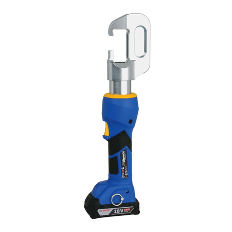
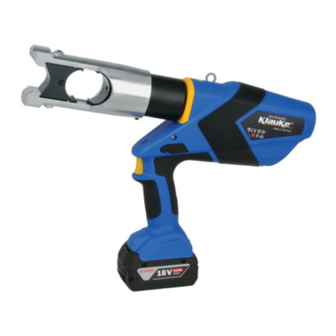
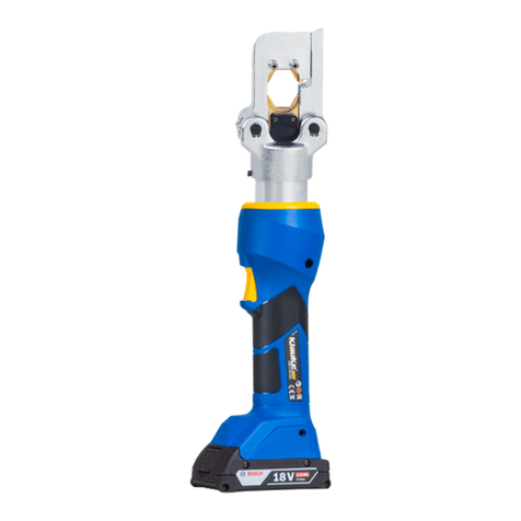
Klauke K-EP 1342 User manual

K-EP 1342
CN.2P015 06/2014 KN
操作使用说明书
Serial Number
序列号

K-EP 1342
I
Bedienungsanleitung/Instruction manual
HE.15508_A © 06/2014
4
3
2
1
87 96
5
2K
1. 2.
3.
OIL
HE.15487
HE.15488
K-EP 1342
Crimping tool
Voltage: 18V DC
Force: 120 kN / 13.5 short tons
HE.15534
%&4*(/&%*/(&3."/:t."%&#:,-"6,&
304711 Öbatch# e.g. 304711
Ö㔈㶰√Ⱁ 304711
GN Ödatecode e.g. G = 2013; N = Jan.
Ö㡴㦮ⅲ䪐√Ⱁ G = 2013; N = 㦗
142 Öconsecutive# e.g. „142“ = tool # 142
Ö䞮ℶㄞ⚆√Ⱁ „142“ = ぴ␆ 142
datecode/㡴㦮ⅲ䪐
Year
Code
ⅲ䪐
Month
㦗
Code
ⅲ䪐
Month
㦗
Code
ⅲ䪐
2013 G Jan.
㦗 NJuly
ₒ㦗 V
2014 H Feb.
ℛ㦗 PAug.
⏺㦗 W
2015 J Mar.
ₘ㦗 QSept.
㦗 X
2016 K Apr.
⥪㦗 ROct.
◐㦗 Y
2017 L May
℣㦗 SNov.
◐㦗 Z
2018 M June
⏼㦗 TDec.
◐ℛ㦗 1
WORK
SERVICE
DON´T DO
1
1
1
2
使用说明书
工作
维修
禁止
CN.2P015 06/2014 KN
01

K-EP 1342
II
Bedienungsanleitung/Instruction manual
Li-ionLi-ion
K-RAL2 60 min.
4 - 40°C
CLICK
N
O
C
H
I
L
D
R
E
N
<
1
6
A
T
W
O
R
K
t
LED1
LED2
LED3
Overvoltage/
Overcurrent
protection
Overtemperature
protection(Hi/Lo)
BatteryfailureChargingfinishedChargingprocess
Status
Connectthechargerintopoweroutletbeforeinsertingbatterypack,allthreechargingLEDs willbeonfortwosecondsand
thenoff
Fastblinking Slowblinking Remainoncontinuously
GB Chin
Tab. 2 / 嫷
When/㢅梃 Why/☮⥯
20 sec
after working cycle
☚㘴⛷㦮⸛㒟⚝
2 x
after inserting the battery
☚㘴⛷㦮⸛㒟⚝
Self check
呹㒠㭏㩴
20 sec/2Hz
after working cycle
☚㘴⛷㦮⸛㒟⚝
Tab. 1 / 嫷
K-LGL1
3
5
6
711
8
9
10 12
4
1. 2.3.
1. 2.3.
13
HE.15508_A © 06/2014
使用说明书
插入电池组前,将充电器接入电源插座,所有三个充电发光二极管将亮2秒,随后关闭。
快速闪烁
状态 充电过程 充电完成 电池故障
超温保护(高/低)
过压/过流保护
缓慢闪烁 一直亮着
02
CN.2P015 06/2014 KN

K-EP 1342
III
Bedienungsanleitung/Instruction manual
PRESS
350°
1.
2.
14 15
16
18
19
17
20
1.
2.
1.
2.
OIL
OIL
HE.15508_A © 06/2014
CLICK
使用说明书
挤压
CN.2P015 06/2014 KN
03

K
-
EP 1342
HE.15508_A © 06/2014 1
GB
1
2
3
3.1
3.2
3.3
4
4.1
4.2
4.3
4.4
5
6
7/
1.
2.
¡¢£¤¥¦§¨©ª«¬
®¯°±² 12 ³¥¢´µ¶·¸
¹º»¼½¾¿¹ÀÁ¢ÂÃ
ÄÅ
3.
3.1
ÆÇÈÉÉÊËÌͦÎÏТ¶·Ñ
Ò3ÓÔÕ 1Ö
1רÙÚÓÛ
ÜÖ
ÝÆÞ߯àáâã
äå
2ÆÞ ߯
3Ah æçèÆÞÓK-RAL2Ö
3Ééê ëìíîëï
4ðñéê äåòóôõö¢÷øð
ñéê
5Éù 120kN CúÉù
6û üýÉû
7ûþ þÿ~û
8î}|É/ò
{
9[\ ]^_[\¦à`@
?>
3.2
ÈÉ{¿=ªÇðñã¦<;:/.
É-,÷ø+*°ìñ{ )('&=%$
Æ#¦ËÇðñ"!÷ø+*0°ìñ{
|{123áÇ4¦Ééêÿ~,
56÷ø/û78Ç
|{1239÷øA¦ûBCDE
¦F,ÉGÇCHIJ
ÉùKLM 350°NOPǦÐüQRS
TUVWXY
|123Za4¦ÝbcdÆÞe
Æfgh¦F,iÉjklªÇïmÆÇ
n
o' USB >14¦Ð,pq,¦
rs|><ãtunavk3wx
y
2K ó]^t2 2¶·ÌX3
¦ÐO[\t=
¦¸8¦£Ð6
2ão3ÉéêàáF9é
ê¦à¦£ÐüÌ
æçèÆÞ2r¦¸ª~Æ
,2¦|ìÐ
[¦FÆÞ¦|ÆÞãfI¦f
ÆÞ. 50%¦£ßÆ,I
3.3
ÔÒ 1
使用说明书
04
CN.2P015 06/2014 KN

K
-
EP 1342
HE.15508_A © 06/2014 2
GB
4.
EN50110-1
XXX-L XXX-L INS
4.1
¡¢£¤
¡¢£¤¥¦§
¨©ª«¬®¯
°±²³´µ¶·¸¹º»
4.2
¼½¾¿ÀÁ³Ã
ÄÅÆ
¥¦§¨©
ª«¬
¨®¯50 °±²
³´ 15
ÇÈÉÊËÌÍÀÎÏÐÑÒ
ÓÔÇÕÖËÌÍרÙÚÛËÌÍÜÝ
ÈËÝÆÞ߯àáâãä
à¼åæç·èåéêÔ
4.3
µ¶·¸¡¢¹º»¼
ëìíîïðÎñòóôÂãäõË
4.4 £¤²¥½
¾¦¿§ÀÁ¥¨À©ª
«
£Â¥°ÃÄÅÃÄÅÆÇ°
ÈÉʬ® 20 ¯°±¡¤ËÌÊ
Í
¥Î 1²°Ï³1´²ÐѵҶ
ÓËÌ·ASCËÌÔÍÕÖר
¸Ù¹ºÚ»°Ûܨ¼
ÕÖ½¾¬ÛݿٹÀÁÂ
ÃÞßÝ
öéê÷øùúºûü
ýÌþÿ~}¥¦§þÿ|{
¦§þÿ[\âËÌ]^Ôµ¶
_`@?
ÑÒÂ>=<;>=ÑÒ:/.
-,+*)
(³'.&% Klauke $#ú"Ö!
"0ÏѦ§
5
aàáÑâãäåÄæÅç 1.1¯¬®/èæÅÆ
ÇÈéÉÊË
ê 1ÌÍßÝëìÒÏ
¶ÓËÌ·ASC
bÎÏ
ëìÐÄÃÑÒÓ
ØÔÐÕÖ
6
×í
î
¿
6,55 kg
Å 120 kN
Ø42 mm
¿ 18V
¿¤í
:
3Ah(K-RAL2)
ÁÊÍ
60
K
-
RAL2
ÊÍ 10Ù14 ¯
Úª¯åÛÜ
¤Ý/
¿
110 ¤
Þï
150 mm² DIN 46235
ÂÏðß
T32
àáñ -20âÙ+40â
Çãä
70dB(A)
1
åæò
ç£ ä
2.5m/s²
ÛÜ ê
2
Klauke
使用说明书
CN.2P015 06/2014 KN
05

HE.15508_A © 06/2014 3
GB
K
-
RAL2
K
-
LGL1
•
•
•
•
•
•¡
¢£¡
•¤¥¦§¨¦©
¡ª«
•¢£¬®¤¥¨¤¥
•¯¦§¨°
•©ª«±²¬³´£®
µ¶¯´·±¨°¸
•±²³´¹µ
¶·¶©º»¸©
¹
•º»¼¼½
½50¾¿¿
ÀÁÂ
•ÃÄž100Æ240V ¿
ÇÀÈÁ
•¶Â¸Éã»ÄÊ˵
ÌÅÍÎϱ
• 18¾24¾ÆÇмº°
ÈÉÊ¥ËÑÊÒÓºÔ¾
Ó 40¾Ð¼Õ̺£Í¹Ö×
©±
•ØÙÄÚÛÂ
ÜÝÞ
•ßàÈÁáÎ
Ï®ÐâãäÑË
•ÈÉÃåæÒçÊ¥
èÓÔéê¢ÍëÕÊì
Ú
•Öí¥ÈÉרîºïð
ñÙ
•º»òÚÛ»ÚÛ
ܼ¼¼óÈ
É
•ßàÝÞºº»«ãä£
°
•ôß¼¼
ßà¼á
¥£Çº»°âõãÍää£
ëö©¤¥ÈÉ
•µ¡åæçÌ
è§·éê
ë÷øÆ
•¤¥¸
•ÔÇêùºïìíÙ
-éêúÜûüý
-Êéê¥îîïëìí
•úîïþ60 ×øéêÍÿ
ëÄð
Klauke18V K-RAL2
©~¢Íë²Í}
•¨~£éê
¢£üý©ºñ 15Æ30 ×ø
°
•¨~Ó£éê
¢£üý©ºñ 15Æ30 ×ø
̰é
êÌüý°«²³
使用说明书
06
CN.2P015 06/2014 KN

K-EP 1342
1
Instruction Manual Crimping Tool
GB
authorised
copy
Index
1 Introduction
2 Warranty
3 Description of the electric-hydraulic
crimping tool
3.1 Description of the components
3.2 Brief description of the important features of
the unit
3.3 Description of the tool indication
4 Remarks in respect of the determined use
4.1 Operation of the unit
4.2 Explanation of the application range
4.3 Mounting instructions
4.4 Service and Maintenance instructions
5 Troubleshooting
6 Technical data
7 Putting out of operation/waste disposal
Symbols
Safety warnings
Please do not disregard these instructions in or-
der to avoid human injuries and environmental
damages.
Operational warnings
Please do not disregard them to avoid dama-
ging the pump unit.
1. Introduction
Before starting to use the tool please read
the instruction manual carefully.
Use this tool exclusively for its determined use.
Mounting and assembly of connecting material with the
help of this tool must only be performed by specially trai-
ned personnel. This instruction manual has to be carried
along during the entire life span of that tool.
The operator has • to guarantee the availability of the
instruction manual for the user and
• to make sure, that the user has read
and understood the instruction manual.
2. Warranty
If the tool is operated according to its intended use and
the regular maintenance services are observed our war-
ranty is 12 months from the time of delivery. Worn-out
parts resulting from its intended use are excluded. We
reserve the right to rework the tool in case of a justied
warranty claim.
3. Description of the electric-
hydraulic crimping tool
3.1 Description of the components
The electric-hydraulic crimping unit is a hand held tool
and consists of the following components:
Table 3 (see Picture 1)
Pos. Description Function
1 LED (red) Indicator for battery charge
control, tool functions and
faults
2 Battery
cartridge
Rechargeable
3Ah Li-Ion battery (K-RAL2)
3 Trigger Switch to start working cycle
4 Retract button Button to retract the piston in
case of error or emergency
5 Crimping head C-shape crimping head for
120kN
6 Dies Interchangeable crimping dies
7 Die lock To lock and release the die
8 Ring Loop to secure the tool and/or
for assembly purposes
9 Housing Ergonomically formed plastic
housing for perfect handling
3.2 Brief description of the important fea-
tures of the unit
The hydraulic unit incorporates an automatic retrac-
tion which returns the piston into its starting position
when the maximum operating pressure is reached.
A manual retraction allows the user to return the pis-
ton into the starting position in case having selected
the wrong cable.
The unit is equipped with a special brake which
stops the forward motion of the piston/dies when
the trigger is released.
The unit is equipped with a double piston pump
which is characterised by a rapid approach of the
dies towards the connector and a slow crimping
motion.
The crimping head can be smoothly turned by 350°
around the longitudinal axis in order to gain better
access to tight corners and other dif cult working
areas.
The tool is equipped with a microprocessor which
shuts off the motor automatically after the crimp is
completed, indicates service intervals and low bat-
tery charges.
Through an optional USB adapter a report can be
generated at the end of a working session at a PC
documenting the proper function of the tool.
The compact ergonomically formed design consists
of 2 components. The grip area is rubber coated
and therefore slip resistent. The housing design is
optimized in respect of the center of gravity which
improves the handling and supports fatique-proof
working.
All tool functions can be controlled by one trigger.
This results in an easy handling and a better grip
compared to a two button operation.
Li-Ion batteries do neither have a memory effect nor
self discharge. Even after long periods of non ope-
ration the tool is always ready to operate. In addition
we see a lower power weight ratio with 50% more
capacity and shorter charging cycles compared to
NiMH batteries.
3.3 Description of the tool indication
See Tab. 1.
2K
HE.15508_A © 06/2014
使用说明书
CN.2P015 06/2014 KN
07

K-EP 1342
2
Instruction Manual Crimping Tool
GB
authorised
copy
4. Remarks in respect of the determined
use
Before starting any work on electrical appliances it must
be safeguarded that there are no live parts in the imme-
diate assembly area of the user. If this not possible spe-
cial precaution measures (e.g. acc. to EN 50110-1) for working
near live parts must be provided.
Keep your working area clean and tidy. Do not use this
tool when you are tired, on drugs, had alcohol or if you
are medicated.
The XXX-L is also available as an XXX-L INS with an in-
sulated head which is specially designed for working near
live lines.
4.1 Operation of the unit
Cycle: see pictures in front
The crimping head should be turned into the desired po-
sition before starting the crimping cycle. It is signicantly
easier to turn the crimping head in a pressure free state.
Attention
After having terminated the working cycle and
prior to changing the dies remove battery to
avoid unintended use. Avoid unintended starts.
Make sure the switch is in the off position before
plugging in.
Attention
Dress properly. Do not wear loose clothing or
jewellery. Keep your hair, clothing and gloves
away from moving parts.
Attention
Keep proper footing and balance at all times.
Attention
Use safety gear and always wear eye protec-
tion.
4.2 Explanation of the application range
Attention
Do not crimp on live cables or conduc-
tors. The tool is not insulated.
The unit is a hand held tool and it is not supposed to be
restrained in a vise. It is not allowed to use the tool in a
stationary application.
The tool is not designed for continued operations. After
a sequence of approximately 50 completed cycles you
have to make a break of 15 min. to give the tool time to
cool down.
Attention
Too intensive use can cause heat damages for
the tool
Attention
During the operation of electric engines sparks
can occur which might ignite highly inammab-
le or explosive liquids and materials
Attention
Electric-hydraulic tools should not be operated
in pouring rain or under water.
4.3 Mounting instructions
Please read the assembly instructions in our general ca-
talogue.
Attention
Even if the code number is identical only those
dies should be used which are suitable for the
material.
4.4 Service and maintenance instruction
For every day service the tool has to be cleaned and dried
after each use. The battery cartridge and the charging unit
have to be protected against humidity and dust.
The electric-hydraulic unit is equipped with a controller
enabling the user to see when the next service is due by
ashing for 20 sec. at the end of a working cycle.
The unit must be sent to an authorized service center
(ASC) after reaching 10.000 cycles or at the latest after
one year. During this service worn out parts will be ex-
changed, safety relevant components checked and pos-
sibly replaced precautiously. This provision serves your
safety and avoids failures through fatigue.
Attention
Maintain power tools thoroughly. Check for
functionality or jamming of moving parts,
breakage of parts and any other condition that
may affect the power tools operation.
Attention
Do not damage the seals of the tool. If the seal
is damaged the warranty claim is void.
Attention
Have damaged parts repaired by a qualied ex-
pert or by a Klauke ASC before use.
5 Troubleshooting
a.) Constant ashing/indicating of the red LED (pic 1.1)
or the occurence of an acoustical warning signal.
Ösee table 1. If the failure can not be solved return the
tool to the nearest service center (ASC).
b.) The tool loses oil.
ÖReturn the unit to the manufacturer. Do not open it and
damage the seal of the tool.
6. Technical Data
Weight
(incl. battery):
6,55 kg
Crimping force: approx. 120 kN
Stroke 42 mm
Battery voltage: 18 V
Battery capacity 3 Ah (K-RAL2)
Charging time: 60 min. (K-RAL2)
Crimping time: approx. 10 s to 14 s
(depending on the connector size)
Crimps
per battery:
approx. 110 crimps
(Cu 150 mm² DIN 46235)
Hydraulic oil: Shell T32
Environmental
temperature:
-12°C to +40°C
Sound level: < 70 dB (A) in 1m distance
Vibrations: < 2,5 m/s²
Dimensions: See Picture 2
Assembled by Klauke in China
from globally sourced components
HE.15508_A © 06/2014
使用说明书
08
CN.2P015 06/2014 KN

3
GB
authorised
copy
Safety rules for battery pack and charger
K-RAL2 K-LGL1
WARNING!
• This manual contains important safety and operating
instructions for your battery and charger. Before using
the charger, read all instructions and warnings on the
charger, the battery pack and the tool.
• If the battery pack casing is cracked or damaged, do
not insert into charger. There is a danger of electric
shock or electrocution.
• Don’t allow any liquid to get inside charger. Electric
shock may result. To facilitate cooling of the battery
pack after use, avoid placing the charger or battery
pack in a warm environment such as in a metal shed,
or a trailer that is not insulated
• This charger is not intended for any uses other than
charging rechargeable batteries. Any other use may re-
sult in risk of re, electric shock or electrocution.
• Do not place any object on top of the charger or place
the charger on a soft surface that may result in excessi-
ve internal heat. Do not place the charger near any heat
source.
• To reduce the potential risk of damage to the electric
plug and cord, pull by the plug rather than the cord
when disconnecting the charger from the power supply.
• Make sure the cord is located so it will not be stepped
on, tripped over, or otherwise subjected to damage or
stress.
• An extension cord should not be used unless absolute-
ly necessary. Use of an improper extension cord could
result in a risk of re, electric shock or electrocution.
• Do not operate the charger if it has received a sharp
blow, been dropped or otherwise damaged in any way.
• Do not disassemble charger. Take it to a Service Agent
when service or repair is required. Incorrect reassembly
may result in a risk of electric shock, electrocution or
re.
• To prevent the risk of electric shock, unplug the charger
from the outlet before attempting to clean it. Removing
the battery pack from the charger is not suf cient to re-
duce this risk.
• DO NOT store or use the tool, charger and battery pack
in locations where the temperature may reach or ex-
ceed 50 °C, as this could lead to deterioration of the
storage battery.
• The charger is designed to operate on standard
household electrical power (100-240 V AC). Do not att-
empt to use it on any other voltage.
Additional information on battery and charger
• The battery pack is not fully charged out of the carton.
First read the safety instructions and then follow the
charging notes and procedures.
• The longest life and best performance can be obtained
if the battery pack is charged when the air temperature
is between 18 and 24 °C. Do not charge the battery
pack where the air temperature is below 4 °C or above
40 °C. This is important and will prevent damage to the
battery pack.
• Do not incinerate the battery pack even if it is seriously
damaged or is completely worn out. The battery can
explode in a re.
• Never attempt to open the battery pack for any rea-
son. If the plastic housing of the battery pack breaks or
cracks, immediately discontinue use and do not rechar-
ge.
• The length of service from your battery will depend on
the type of work you are doing. The battery has been
designed to provide maximum trouble-free life. Howe-
ver, like all batteries, it will eventually wear out.
• To obtain the longest possible battery life, we suggest
the following:
• Store and charge your battery in a cool area. Tempe-
ratures above or below normal room temperature will
shorten battery life.
• Never store the battery in a discharged condition. Re-
charge it immediately after it has been discharged.
• All batteries gradually lose their charge. The higher the
temperature, the quicker they lose their charge.
If you store your tool for long periods of time without use,
recharge the battery every month or two. This practice will
prolong battery life.
CHARGING PROCEDURE
• Connect the plug cable to the charger, and then plug
into an appropriate outlet before inserting battery pack.
All three charging lights will be on for two seconds and
then off.
• Insert the battery pack into the charger, making sure the
pack is fully seated in the charger.
• During the charging process, the charging lights will in-
dicate the charging status as follows:
- Three charging lights will blink in sequence during the
charging process
- Fully charged, all three lights will remain on conti-
nuously.
• The charging process will last approximately 60 minu-
tes and permanent lighting of all three charging lights
will indicate charging is complete.
NOTE:
This charger can only charge the Klauke 18V batte-
ry pack K-RAL2.
CHARGER DIAGNOSTICS
The charger is designed to detect certain problems that
can arise with battery packs.
• When the charger detects a battery pack that is overhe-
ated, all three charging lights will blink at the same time.
Please remove the battery and allow it to cool down for
15-30 minutes and re-insert.
• When the charger detects a malfunction in the batte-
ry or the charger, two charging lights will blink at the
same time. Please remove the battery and allow it to
cool down for 15-30 minutes. Then re-insert the battery
pack into the charger. If two charging lights still ash,
the battery or charger may require service.
NOTE:
Charging times maybe longer depending on the
surrounding temperature and battery conditions.
HE.15508_A © 06/2014
使用说明书
CN.2P015 06/2014 KN
09

EMERSON PROFESSIONAL TOOLS
地址:上海松江工业区江田东路89号 电话:400-820-5695 www.klauke.com.cn
Table of contents
Other Klauke Power Tools manuals

Klauke
Klauke EK 22 User manual

Klauke
Klauke EK 35/4-L User manual

Klauke
Klauke EK 60 VPFT-L User manual

Klauke
Klauke EK 50/18CFB User manual

Klauke
Klauke Uponor Unipipe UP 75 User manual

Klauke
Klauke Axelent EBS6GKSNGBAX User manual

Klauke
Klauke EK 60UNV-L User manual

Klauke
Klauke EK 135L User manual

Klauke
Klauke EK 425-L User manual

Klauke
Klauke EK 15/50 User manual

Klauke
Klauke HENCO UNP 2 User manual

Klauke
Klauke EK 19 plus User manual

Klauke
Klauke EK 50 User manual

Klauke
Klauke EK 120 User manual

Klauke
Klauke EK 120/25-L User manual

Klauke
Klauke EKP 1 User manual

Klauke
Klauke AHP 700-L User manual

Klauke
Klauke EK 60 VP INS User manual

Klauke
Klauke UAP3L User manual

Klauke
Klauke HK 4 User manual