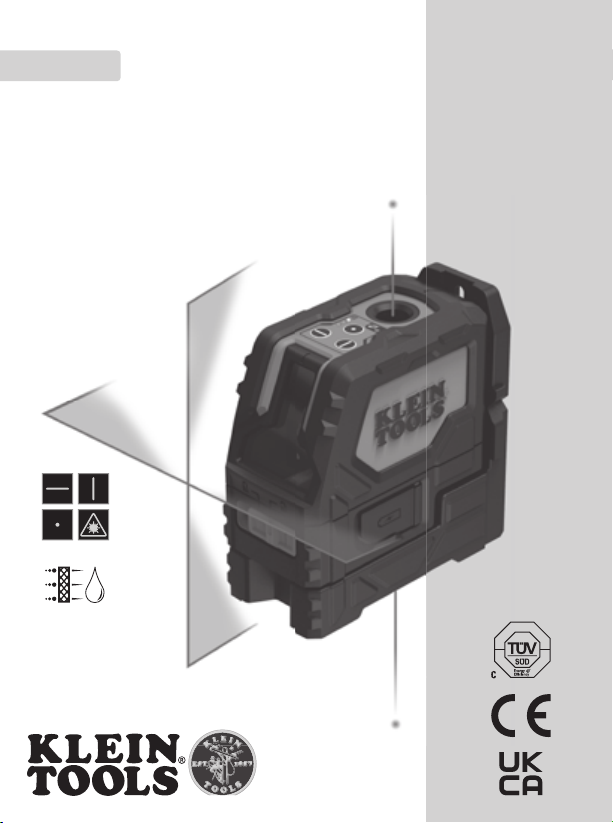
Klein Tools 93LCLGR User manual

Rechargeable Self-Leveling
Cross Line Laser Level with Plumb Spot
INSTRUCTION MANUAL
FRANÇAIS p. 25
ESPAÑOL pg. 13
ENGLISH
• HORIZONTAL AND
VERTICAL CROSS LINES
• PLUMB SPOT
93LCLGR
IP54

2
GENERAL SPECIFICATIONS
Klein Tools 93LCLGR is a self-leveling laser alignment instrument that can be used to deliver
horizontal and/or vertical cross lines for alignment and layout applications. Furthermore,
93LCLGR can also deliver a plumb spot directly above the instrument.
• Operating Altitude: 6562 ft. (2000 m)
• Relative Humidity: <80% non-condensing
• Operating Temp: 20°F to 115°F (-10°C to 45°C)
• Storage Temp: -5°F to 140°F (-20°C to 60°C)
• Laser: 510-530 nm (cross lines) 630-680 nm (plumb spots). ≤ 1mW each beam,
Class 2 Laser Product
• Accuracy: ±1/8" per 50' (±3 mm per 15 m) Vertical and Horizontal Beams;
±3/16" per 50' (±4.5 mm per 15 m) Plumb up spot;
±1/4" per 50' (±6 mm per 15 m) Plumb down spot
• Battery Type: Li-ion, 3.7V, 6400 mAh (23.68Wh)
• Dimensions: 5.3" × 5.2" × 2.6" (134 × 132 × 66 mm)
• Weight: 29.6 oz (840 g)
• Calibration: Accurate for one year
• Certications: CE, UKCA, ROHS, REACH, DOE/CEC, NRCan
• Standards: Conforms to: EN61326-1:2013, EN60825-1:2014.
Complies with 21 CFR 1040.10 and 1040.11 except for conformance with
IEC 60825-1 Ed. 3., as described in Laser Notice No. 56, dated May 8, 2019.
• Ingress Protection: IP54 Dust & Water Resistant
Specifications subject to change.
ENGLISH

3
WARNINGS
To ensure safe operation and service of the instrument, follow these instructions. Failure
to observe these warnings can result in serious personal injury, re, or electrical shock.
Retain these instructions for future reference.
WARNING: LASER RADIATION. DO NOT STARE INTO BEAM. Class II Laser.
• Exposing eyes to laser radiation can result in severe and permanent eye injuries. NEVER look
directly into the laser beam emitted by this instrument.
• Do not use the instrument if it appears to be damaged.
• Do not modify the instrument in any way, as to do so could result in emission of hazardous laser
radiation than could result in severe eye injuries .
• Do not use optical equipment such as lenses, prisms, optical scopes, etc. to transmit, retransmit,
or view the laser beam as this could result in severe eye injuries.
• This product should not be used by untrained operators or operators who have not read and fully
understood the instructions.
• This product should not be used in any location that could result in somebody looking at or having
their eyes inadvertently irradiated by the laser beam as this could result in severe eye injuries.
• The instrument should be powered off following use to minimize the risks of inadvertently
exposure to hazardous laser radiation that could result in severe eye injuries.
• Do not remove warning labels from this instrument as this could result in serious personal injury
and increases the risk of exposure to hazardous laser irradiation.
• Risk of fire and burns. DO NOT open, crush, heat above specified maximum temperature or
incinerate. Prolonged exposure to direct sunlight can result in elevated temperatures.
• DO NOT immerse in water or other liquids.
• Properly seal the charging port cover to achieve specified water & foreign object ingress
protection. Keep seal free of dirt, oil, sand, or other material that interferes with proper sealing.
Failure to do so can result in risk of fire or electric shock.
• DO NOT open the charging port cover if wet or in a wet environment. Thoroughly dry the unit and
the seal around water-resistant cover completely before opening water resistant cover.
• DO NOT subject to excessive vibration, impacts, or drops. The housing may not show signs of
damage, but internal components may have been compromised. It is advisable to replace the unit
if any such severe events occur.
• DO NOT attempt to repair the product or charging cable. There are no user-serviceable parts.
Warning label
on side of
93LCLGR

4
FEATURE DETAILS
NOTE: There are no user-serviceable parts inside this instrument.
SYMBOLS ON INSTRUMENT
Vertical
Laser Line Battery Status Indicator Ingress Protection IP54 Rating –
Dust & Water Resistant
Horizontal
Laser Line Excessive Tilt Indicator Hazardous laser radiation
Plumb Spot
Laser Warning or Caution Risk of Electrical Shock
WEEE:
Electronics
disposal
Conformité Européenne:
Conforms with European
Economic Area directives UKCA: UK Conformity Assessment
Laser Class 2 DO NOT stare into beam or view
directly with optical instruments
Read instructions
ENGLISH
1. Horizontal Line On/Off Button 10. Plum Spot Aperture
2. Vertical Line On/Off Button 11. USB Port Cover
3. Plum Spot On/Off Button 11a. USB Charging Port
4. Battery Status Indicator 12. 1/4-20 Tripod Mount
5. Excessive Tilt Indicator 13. 5/8-11 Survey Tripod Mount
6.
Power/Pendulum Lock/Unlock Switch
14. Magnetic Mount Bracket
7. Pendulum with Lasers 15. Magnets
8. Horizontal Line Aperture 16. Clamp-On Wall Adapter
9. Vertical Line Aperture 17. USB Charging Cable
16
13
45
2
7
89
6
14
15
12
13
17 11
10
11a
BOTTOM
VIEW

5
OPERATING INSTRUCTIONS
TURNING LASER BEAMS ON/OFF
Push the ON/OFF buttons for the horizontal line
1
, vertical line
2
, and plumb spot
3
to turn ON and OFF their respective laser lines. These buttons are only active once the
Pendulum Lock/Unlock Slider Switch
6
has been set to the Unlocked position. If the
Pendulum Slider Switch is moved from the Unlocked to the Locked position while the
laser beams are active, they will be turned OFF. The different laser lines can be operated
independently or simultaneously.
NOTE: The plumb spot application projects laser beams both in upward and downward
directions. The downward beam may be used to locate a specific point on a floor layout
while the upward beam projects that same point to a ceiling.
PENDULUM SLIDER SWITCH & SELF-LEVELING
The laser assemblies are mounted on a pendulum so that the instrument can self-level. The
Pendulum Slider Switch
6
must be in the unlocked position for the instrument to self-level.
If the instrument is tilted by >6°from the horizontal plane, the pendulum will not be capable
of self-leveling; the active laser beams will flash and the Excessive Tilt Indicator
5
will blink
to indicate that the instrument is not level and cannot self-level. The instrument must be
repositioned on a more level surface for the self-leveling pendulum to function appropriately.
Horizontal Laser LineHorizontal Laser Line Vertical Laser LineVertical Laser Line Plumb Laser LinePlumb Laser Line
NOTE: If the instrument indicates that it is not level
(via flashing beams and/or a blinking Excessive Tilt
indicator
5
),
then it should not be used for laying
out level or plumb lines.
NOTE: Following use, the active laser beams must be
turned OFF and the Pendulum Slider Switch must be
placed in the Locked position prior to storage.
Instrument Tilted Excessively

6
OPERATING INSTRUCTIONS
MAGNETIC MOUNTING BRACKET
14
The instrument is attached to a magnetic mounting bracket. The bracket may be
magnetically attached to any magnetic structure such as steel studs, ducts, structural
beams, and steel doors. The bracket also features a key-hole for mounting the instrument
using a screw or nail to non-magnetic structures. Once mounted to a structure via the
mounting bracket the instrument can be rotated on the bracket through 360°to direct the
laser beams.
CLAMP-ON WALL ADAPTER
16
The clamp-on wall adapter may be clamped to a structural beam, or wall bracket for
suspended ceiling installations, to present a steel surface onto which the instrument's
magnetic mounting bracket may be attached. Once magnetically attached the instrument
may be positioned to deliver the laser line at the required location. The clamp-on adapter
also features a key-hole for mounting the instrument using a screw or nail.
Mounted via keyholeMounted via keyholeMounted via magnetMounted via magnet
Adapter mounted on ceiling bracketAdapter mounted on ceiling bracket Adapter mounted via keyholeAdapter mounted via keyhole
ENGLISH

7
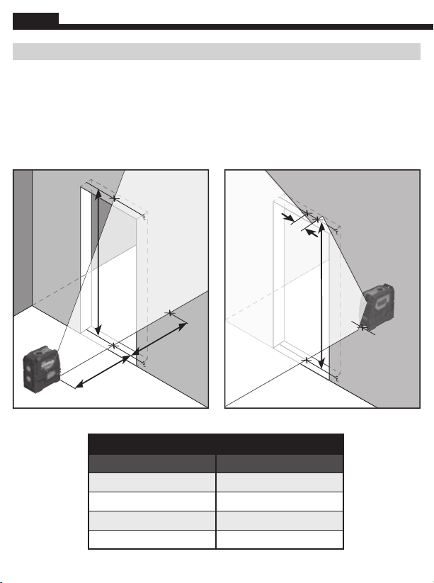
VERIFYING ACCURACY OF LASER LINES
HORIZONTAL BEAM LEFT/RIGHT TILT
Position the instrument on the floor xdistance from front of the device to the vertical wall as shown.
Rotate the instrument on the bracket to the left so that the right side of the beam is projected on
the wall directly across from the instrument, mark the vertical location on the wall (a). Rotate the
instrument to the right and repeat marking the vertical location of the left side of the beam (b).
The
maximum distance (delta) between aand bis shown in the table below.
HORIZONTAL BEAM OUT-OF-PLANE TILT
Position the instrument parallel to a wall and project a beam along the wall, from left to right as
shown. Mark two locations (a, b) along the beam separated by distance x. Position the laser at the
other side of the wall and project the beam back through mark b, from right to left as shown, and
mark position c.
The maximum distance (delta) between aand cis shown in the table below.
b
ax
b
a
c
x
HORIZONTAL BEAM LEFT/RIGHT TILT
Distance From Wall (x) Delta
15' (4.6 m)
~1/16" (1.5 mm)
30' (9.1 m)
~1/8" (3 mm)
HORIZONTAL BEAM OUT OF PLANE TILT
Distance From Wall (x) Delta
10' (3.1 m)
~1/16" (1.5 mm)
25' (7.6 m)
~1/8" (3 mm)
a
x
a
b
x
8
ENGLISH
VERIFYING ACCURACY OF LASER LINES
Vertical Beam Tilt
Position the instrument on the floor 10' (3.05 m) away from the center of a door opening.
Project the vertical beam through the doorway, marking points aand cin the center of the
door opening. Mark point bon the floor 10' (3.05 m) past the doorway. Move the device
behind point band project the vertical laser line through points band a. Measure the distance
between point cand the laser line (point d). For the vertical height of the doorway, distance x,
the maximum distance (delta) between cand dis shown in the table below.
10'
(3.05 m)
10'
(3.05 m)
a
b
x
c
a
x
cd
b
VERTICAL BEAM TILT
Door Height (x) Delta
8' (2.5 m)
~1/32" (1 mm)
14' (4 m)
~1/16" (1.5 mm)
20' (6 m)
~3/32" (2.4 mm)
30' (9 m)
~5/32" (3.6 mm)

9
VERIFYING ACCURACY OF LASER LINES
PLUMB SPOT
Position instrument on the floor and project a spot with the plumb spot laser to the ceiling
(a). Rotate the laser by 180°and project the exact same spot to the ceiling (b). The maximum
distance (delta) between aand bis shown in the table below.
PLUMB SPOT TILT
Distance From Ceiling (x) Delta
12.5' (3.8 m)
~3/32" (2.3 mm)
25' (7.6 m)
~3/16" (4.5 mm)
a
x
ab
10
ENGLISH
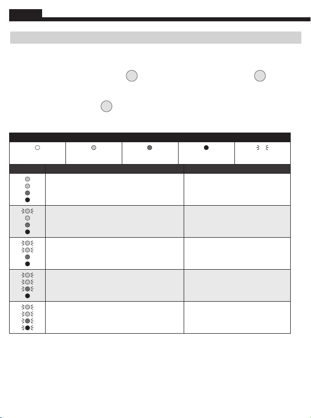
RECHARGING BATTERY
When the Red LED on the Battery Level Indicator blinks, the battery needs to be recharged:
Charging Battery via 93LCLGR USB-C Port:
1. Connect supplied charging cable’s
17
USB-C connection to the USB-C port
11a
of the
93LCLGR.
2. Connect the charging cable’s USB-A port to a charging source (5V DC, Min 2.0A, not included).
3. The Battery Level Indicator
4
will illuminate to indicate charging status (TABLE 1).
4. A full charge can take up to 8.5 hours, depending on the charger’s output. Charge completely
before using.
TABLE 1
Not Illuminated Green Yellow Red Blinking
LED Status % Charged
Solid green
Solid green
Solid yellow
Solid red
100% charged
Blinking green
Solid green
Solid yellow
Solid red
75% to 99% charged
Blinking green
Blinking green
Solid yellow
Solid red
50% to 74% charged
Blinking green
Blinking green
Blinking yellow
Solid red
25% to 49% charged
Blinking green
Blinking green
Blinking yellow
Blinking red
0% to 24% charged

11
INSPECTION
Regularly inspect ports and charging cable for debris, dirt, damage, and corrosion. DO NOT
attempt to repair device or cable; replace as needed.
CLEANING
Be sure laser level is turned off and disconnected from all power sources. Wipe with
a clean, dry lint-free cloth.
Do not use abrasive cleaners or solvents.
STORAGE
If storing for more than one month, charge completely before storage, and recharge
approximately every three months to avoid full discharge. Store in cool temperatures, mild
humidity, and away from direct sunlight (See GENERAL SPECIFICATIONS section). Leaving
in a vehicle or other confined spaces in extreme hot temperatures can lead to decrease in
service life, overheating, or fire. Extreme cold temperatures below the specified storage
range can also harm performance and service life. Keep away from corrosive chemicals and
gases. After taking out of storage, inspect visually to make sure device and all accessories
look satisfactory. Allow unit to return to ambient conditions before recharging.
FCC AND IC COMPLIANCE
See this product’s page at www.kleintools.com for FCC compliance information.
Canada ICES-003 (B) / NMB-003 (B)
WARRANTY
www.kleintools.com/warranty
DISPOSAL /RECYCLE
Do not place equipment and its accessories in the trash. Items must be
properly disposed of in accordance with local regulations. Please see
www.epa.gov/recycle for additional information.
CUSTOMER SERVICE
KLEIN TOOLS, INC.
450 Bond Street Lincolnshire, IL 60069 1-800-553-4676
[email protected] www.kleintools.com

12
NOTES
ENGLISH
Nivel láser autonivelante de líneas
encruzrecargable con punto de plomada
MANUAL DE INSTRUCCIONES
ESPAÑOL
• LÍNEAS HORIZONTALES
YVERTICALES EN CRUZ
• PUNTO DE PLOMADA
93LCLGR
IP54

14
ESPECIFICACIONES GENERALES
El 93LCLGR de Klein Tools es un instrumento de alineación láser autonivelante que se puede usar para
proyectar líneas horizontales y/o verticales en cruz, y es útil para aplicaciones de posición de elementos
y alineación. Además, el 93LCLGR también proporciona un punto de plomada directamente desde la
parte superior del instrumento.
• Altitud de funcionamiento: 6562' (2000m)
• Humedad relativa: <80%, sin condensación
• Temperatura de funcionamiento: 20°F a 115°F (-10°C a 45°C)
• Temperatura de almacenamiento: -5°F a 140°F (-20°C a 60°C)
• Láser: 510 a 530nm (líneas en cruz) 630 a 680nm (puntos de plomada). ≤1mW por haz,
producto con láser Clase 2
• Precisión: haz vertical y horizontal de ±1/8" cada 50' (±3mm cada 15m);
punto de plomada superior de ±3/16" cada 50' (±4,5mm cada 15m);
punto de plomada inferior de ±1/4" cada 50' (±6mm cada 15m)
• Tipo de batería: iones de litio, 3,7V, 6400mAh (23,68Wh)
• Dimensiones: 5,3"×5,2"×2,6"(134×132×66mm)
• Peso: 29,6oz (840g)
• Calibración: precisa durante un año
• Certicaciones: CE, UKCA, ROHS, REACH, DOE/CEC, NRCan
• Normas: cumple con: EN61326-1:2013, EN60825-1:2014.
Cumple con las normas 21 CFR 1040.10 y 1040.11, excepto en lo referente
alaconformidad con IEC 60825-1 Ed. 3., como se describe en el aviso sobre
lásern.º56del 8 de mayo de 2019.
• Protección de ingreso: IP54: resistente al agua y al polvo
Especificaciones sujetas a cambios.
ESPAÑOL

15
ADVERTENCIAS
Para garantizar el funcionamiento y servicio seguros del instrumento, siga estas
instrucciones. El incumplimiento de estas advertencias puede provocar lesiones
personales graves, incendio o choques eléctricos. Guarde estas instrucciones
paraconsultarlas en el futuro.
ADVERTENCIA: RADIACIÓN LÁSER. NO MIRAR EL HAZ. Láser Clase II.
• Exponer la vista a la radiación láser puede provocar lesiones oculares graves e irreversibles. NUNCA mire
directamente el haz de láser que emite el instrumento.
• No utilice el instrumento si en apariencia está dañado.
• No modifique el producto de ninguna manera, ya que esto puede provocar la emisión de radiación láser
peligrosa que, a su vez, puede ocasionar lesiones oculares graves.
• No utilice equipos ópticos como lentes, prismas, telescopios ópticos, etc. para transmitir, retransmitir
overelhaz del láser, dado que esto puede ocasionar lesiones oculares graves.
• No deben usar este producto operadores sin capacitación o que no hayan leído ni comprendido
completamente las instrucciones.
• Este producto no se debe utilizar en sitios donde alguien pueda mirar el haz o donde los ojos queden
expuestos accidentalmente a la radiación del haz, dado que esto puede ocasionar lesiones oculares graves.
• Apague el instrumento después de utilizarlo para minimizar los riesgos de una exposición accidental a la
radiación láser peligrosa que podría provocar lesiones oculares graves.
• No quite las etiquetas de advertencia del instrumento ya que esto puede dar lugar a lesiones graves y
aumentar el riesgo de exposición a radiación láser peligrosa.
• Riesgo de incendio y quemaduras. NO lo abra, aplaste, caliente a más de la temperatura máxima especificada,
ni lo incinere. La exposición prolongada a la luz solar directa puede provocar temperaturas elevadas.
• NO lo sumerja en agua u otros líquidos.
• Selle correctamente la cubierta del puerto de carga para lograr la protección especificada contra el ingreso
de agua y objetos extraños. Procure que el sello no contenga suciedad, aceite, arena u otros materiales que
afecten un sellado adecuado. De lo contrario, puede provocar riesgo de incendio o choque eléctrico.
• NO abra la cubierta del puerto de carga si está húmeda o si está en un ambiente húmedo. Seque
cuidadosamente la unidad y el sello alrededor de la cubierta resistente al agua antes de abrir la cubierta
resistente al agua.
• NO lo someta a vibraciones excesivas, impactos o caídas. Es posible que la carcasa no muestre señales de
daño, pero los componentes internos podrían estar comprometidos. Se recomienda reemplazar la unidad
sisufre alguno de estos eventos de gravedad.
• NO intente reparar el producto ni el cable de carga. No contiene piezas que el usuario pueda reparar.
Etiqueta de advertencia
en la parte lateral del
93LCLGR

16
DETALLES DE LAS CARACTERÍSTICAS
NOTA: este producto no contiene en su interior piezas que el usuario pueda reparar.
SÍMBOLOS EN EL INSTRUMENTO
Línea láser
vertical Indicador de estado de la batería Clasificación IP54 de protección de
ingreso: resistente al agua y al polvo
Línea láser
horizontal Indicador de inclinación excesiva Radiación láser peligrosa
Láser de punto
deplomada Advertencia o precaución Riesgo de choque eléctrico
WEEE: eliminación
de elementos
electrónicos
Conformité Européenne: cumple
con las normas del Espacio
EconómicoEuropeo
UKCA: conformidad evaluada por
elReinoUnido
Láser Clase2 NO mirar el haz de luz ni mirar
directamente con instrumentos ópticos
Lea las instrucciones
1.
2.
3.
4.
5.
6.
7.
8.
9.
Botón de encendido y apagado
de la líneahorizontal
Botón de encendido y apagado de la línea vertical
Botón de encendido y apagado
del punto deplomada
Indicador de estado de la batería
Indicador de inclinación excesiva
Interruptor de bloqueo/desbloqueo del péndulo
ydeencendido
Péndulo con láseres
Apertura de línea horizontal
Apertura de línea vertical
10.
11.
11a.
12.
13.
14.
15.
16.
17.
Apertura de punto de plomada
Cubierta del puerto USB
Puerto de carga USB
Orificio de montaje para trípode
de 1/4-20
Orificio de montaje para trípode
topográfico de 5/8-11
Soporte magnético de montaje
Imanes
Adaptador de sujeción para pared
Cable de carga USB
16
13
45
2
7
89
6
14
15
12
13
17 11
10
11a
VISTA
INFERIOR
ESPAÑOL

17
INSTRUCCIONES DE FUNCIONAMIENTO
APAGADO/ENCENDIDO DE LOS HACES DEL LÁSER
Presione los botones de encendido y apagado para encender y apagar la línea horizontal
1
, la línea
vertical
2
y el punto de plomada
3
respectivamente. Estos botones solo están activos una vez
que el interruptor deslizante para bloquear y desbloquear el péndulo
6
se coloca en la posición de
desbloqueado. Si se mueve el interruptor deslizante del péndulo de la posición de desbloqueo a la
posición de bloqueo mientras los haces del láser están activos, estos se apagarán. Las diferentes líneas
del láser pueden funcionar independientemente o en forma simultánea.
NOTA: la aplicación de punto de plomada proyecta los haces del láser en dirección hacia arriba y hacia
abajo. El haz hacia abajo se puede utilizar para ubicar un punto específico enelpiso mientras el haz
hacia arriba proyecta ese mismo punto en el cielorraso.
INTERRUPTOR DESLIZANTE DEL PÉNDULO Y AUTONIVELANTE
Los conjuntos láser están montados sobre un péndulo para que el instrumento pueda autonivelarse.
Elinterruptor deslizante del péndulo
6
debe estar en la posición de desbloqueo para que el instrumento
se autonivele. Si se inclina el instrumento un ángulo de más de 6°respecto del plano horizontal, el
péndulo no podrá autonivelarse. Los haces del láser activos se encenderán en forma intermitente y el
indicador de inclinación excesiva
5
parpadeará para señalar que el instrumento no está nivelado y que
no puede autonivelarse. Deberá reposicionar el instrumento en una superficie más nivelada para que el
péndulo autonivelante funcione correctamente.
Línea láser horizontalLínea láser horizontal Línea láser verticalLínea láser vertical Línea láser de plomadaLínea láser de plomada
NOTA: si el instrumento indica que no está nivelado (los
haces del láser se encienden de manera intermitente o el
indicador de inclinación excesiva
5
parpadea)
,
no se lo
debe utilizar para nivelación de posición de elementos o
líneas de plomada.
NOTA: después del uso y antes de guardar el instrumento,
los haces del láser activos se deben APAGAR y el interruptor
deslizante del péndulo se debe colocar en la posición
debloqueo.
Inclinación excesiva
delinstrumento

18
INSTRUCCIONES DE FUNCIONAMIENTO
SOPORTE MAGNÉTICO DE MONTAJE
14
El instrumento está acoplado a un soporte magnético de montaje. Este soporte se puede fijar
magnéticamente a cualquier estructura magnética, como pernos de acero, conductos, perfiles laminados
y puertas de acero. También cuenta con un orificio de montaje que sirve para fijar el instrumento sobre
estructuras no magnéticas utilizando un tornillo o clavo. Una vez que el instrumento está fijado a una
estructura mediante su soporte de montaje, se lo puede rotar sobre el soporte 360°para dirigir los
haces del láser en la dirección que se desee.
ADAPTADOR DE SUJECIÓN PARA PARED
16
Este adaptador se puede fijar a un perfil laminado o a un soporte de pared en instalaciones de cielorraso
suspendido de modo tal que quede expuesta la superficie de acero sobre la cual se acoplará el soporte
magnético de montaje del instrumento. Una vez que el instrumento queda fijado de forma magnética,
se lo puede posicionar para que proporcione una línea láser en la ubicación requerida. El adaptador de
sujeción para pared también cuenta con un orificio de montaje para fijar el instrumento utilizando un
tornillo o clavo.
Montado mediante oricio de montajeMontado mediante oricio de montajeMontado mediante imánMontado mediante imán
Adaptador montadoAdaptador montado
sobreelsoporte del cielorrasosobreelsoporte del cielorraso Adaptador montadoAdaptador montado
medianteoricio de montajemedianteoricio de montaje
ESPAÑOL

19
VERIFICAR LA PRECISIÓN DE LAS LÍNEAS DEL LÁSER
INCLINACIÓN DEL HAZ HORIZONTAL HACIA LA IZQUIERDA/DERECHA
Coloque el instrumento sobre el piso a la distancia xdesde la parte frontal del dispositivo y hasta la
pared vertical, como se muestra. Rote el instrumento sobre el soporte hacia la izquierda para que el lado
derecho del haz se proyecte sobre la pared directamente en frente del instrumento, marque la ubicación
vertical en la pared (a). Rote el instrumento hacia la derecha y repita la marca de la ubicación vertical del
lado izquierdo del haz (b). La distancia máxima (delta) entre ay bse muestra en la tabla a continuación.
INCLINACIÓN FUERA DE PLANO DEL HAZ HORIZONTAL
Posicione el instrumento paralelo a una pared y proyecte un haz a lo largo de la pared, de izquierda
a derecha, como se muestra en la figura. Marque las dos ubicaciones (a, b) del haz separadas por la
distancia x. Posicione el láser en el otro lado de la pared y proyecte el haz hacia la marca b, de derecha
a izquierda, como se muestra, y marque las posición c. La distancia máxima (delta) entre ay cse
muestra en la tabla a continuación.
b
ax
b
a
c
x
INCLINACIÓN DEL HAZ HORIZONTAL HACIA LA IZQUIERDA/DERECHA
Distancia de la pared (x) Delta
15' (4,6m)
~1/16" (1,5mm)
30' (9,1m)
~1/8" (3mm)
INCLINACIÓN FUERA DE PLANO DEL HAZ HORIZONTAL
Distancia de la pared (x) Delta
10' (3,1m)
~1/16" (1,5mm)
25' (7,6m)
~1/8" (3mm)
a
x
a
b
x

20
VERIFICAR LA PRECISIÓN DE LAS LÍNEAS DEL LÁSER
Inclinación del haz vertical
Coloque el instrumento sobre el piso a 10' (3,05m) del centro de la abertura de una puerta. Proyecte
el haz vertical a través del umbral de la puerta, y marque los puntos ay cen el centro de la abertura
de la puerta. Marque el punto bsobre el piso, a 10' (3,05m) más allá del umbral de la puerta. Mueva
el dispositivo detrás del punto by proyecte la línea láser vertical a través de los puntos by a. Mida la
distancia entre el punto cy la línea láser (punto d). Para la altura vertical del umbral de la puerta, la
distancia x, la distancia máxima (delta) entre cy dse muestra en la tabla a continuación.
10'
(3,05m)
10'
(3,05m)
a
b
x
c
a
x
cd
b
INCLINACIÓN DEL HAZ VERTICAL
Altura de la puerta (x) Delta
8' (2,5m)
~1/32" (1mm)
14' (4m)
~1/16" (1,5mm)
20' (6m)
~3/32" (2,4mm)
30' (9m)
~5/32" (3,6mm)
ESPAÑOL
Table of contents
Languages:
Other Klein Tools Laser Level manuals

Klein Tools
Klein Tools 93LCL User manual

Klein Tools
Klein Tools 93LCLG User manual

Klein Tools
Klein Tools 93LCLG User manual

Klein Tools
Klein Tools LBL100 User manual

Klein Tools
Klein Tools 93PLL User manual

Klein Tools
Klein Tools 93LCLS User manual

Klein Tools
Klein Tools 93PLL User manual

Klein Tools
Klein Tools 93LCL User manual


