Klein Tools 93LCLG User manual

INSTRUCTION MANUAL
日本語 p. 21
한국어 pg. 11
93LCLG
Self-Leveling Green Cross Line
Laser Level with Red Plumb Spot
ENGLISH
• HORIZONTAL
AND VERTICAL
CROSS LINES
• PLUMB SPOT
IP54
93LCLG

2
ENGLISH
GENERAL SPECIFICATIONS
Klein Tools 93LCLG is a self-leveling laser alignment instrument that can be used to
deliver horizontal and/or vertical cross lines, and/or plumb spots directly above/below the
instrument, for alignment and layout applications.
• Operating Altitude: 6562 ft. (2000 m)
• Relative Humidity: <80% non-condensing
• Operating Temp: 20°F to 115°F (-10°C to 45°C)
• Storage Temp: -5°F to 140°F (-20°C to 60°C)
• Lasers: • 515-530 nm (cross lines)
• 630-680 nm (plumb spots)
• ≤1mW each beam, Class II Laser Product
• Accuracy: ±3/32" per 33' (±2 mm per 10 m) Vertical & Horizontal Beams
±1/8" per 33' (±3 mm per 10 m) Plumb Up Spot
±5/32" per 33' (±4 mm per 10 m) Plumb Down Spot
• Battery Type: 3 x 1.5V AA Alkaline
• Dimensions: 5.3" x 5.0" x 2.8" (134 x 127 x 65 mm)
• Weight: 26 oz. (820 g) without batteries
• Calibration: Accurate for one year
• Standards: Conforms to: EN61326-1:2013, EN60825-1:2014.
Complies with 21 CFR 1040.10 and 1040.11 except for conformance with
IEC 60825-1 Ed. 3., as described in Laser Notice No. 56, dated May 8, 2019.
• Ingress Protection: IP54 Dust & Water Resistant
• Electromagnetic Environment: IEC EN61326-1:2013. This equipment meets
requirements for use in basic and controlled electromagnetic environments like
residential properties, business premises, and light-industrial locations.
Specifications subject to change.

3
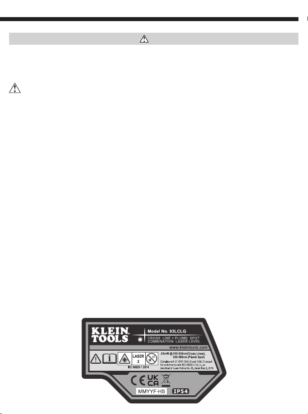
WARNINGS
To ensure safe operation and service of the instrument, follow these instructions. Failure
to observe these warnings can result in serious personal injury, re, or electrical shock.
Retain these instructions for future reference.
WARNING: LASER RADIATION. DO NOT STARE INTO BEAM. Class II Laser.
• Exposing eyes to laser radiation can result in severe and permanent eye injuries. NEVER look
directly into the laser beam emitted by this instrument.
• Do not use the instrument if it appears to be damaged.
• Do not modify the instrument in any way, as to do so could result in emission of hazardous laser
radiation than could result in severe eye injuries .
• Do not use optical equipment such as lenses, prisms, optical scopes, etc. to transmit, retransmit,
or view the laser beam as this could result in severe eye injuries.
• This product should not be used by untrained operators or operators who have not read and fully
understood the instructions.
• This product should not be used in any location that could result in somebody looking at or having
their eyes inadvertently irradiated by the laser beam as this could result in severe eye injuries.
• The instrument should be powered off following use to minimize the risks of inadvertently
exposure to hazardous laser radiation that could result in severe eye injuries.
• Do not remove warning labels from this instrument as this could result in serious personal injury
and increases the risk of exposure to hazardous laser irradiation.
• The instrument should be securely located in a tidy work environment prior to operation as
unexpected drops or movement of the instrument may result in damage to the instrument and
increases the risk of inadvertent exposure to laser radiation that could result in severe eye injuries.
• This instrument is IP54 dust & water resistant. Following any contact with water, thoroughly dry
the instrument with a dry, lint-free cloth.
• There are no user serviceable parts in this instrument.
Warning label
on side of
93LCLG
4
ENGLISH
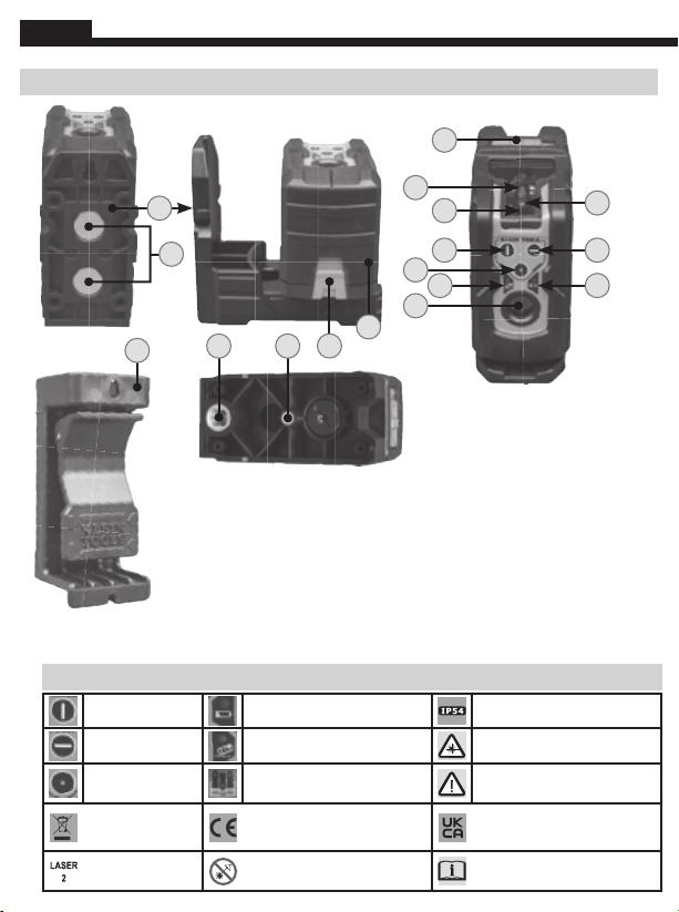
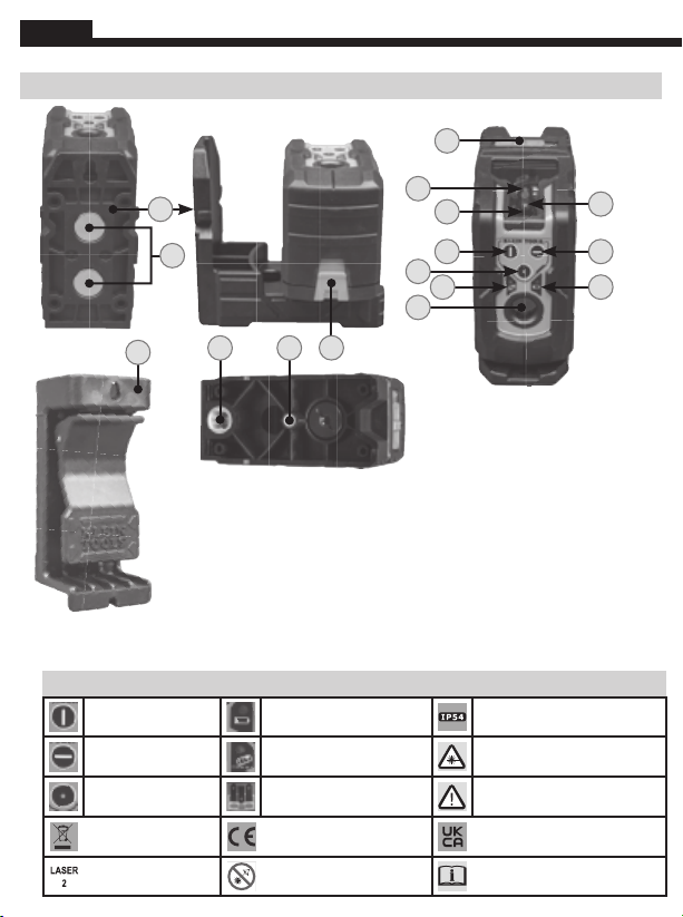
7. Pendulum with Lasers
8. Horizontal Line Aperture
9. Vertical Line Aperture
10. Plumb Spot Aperture
1. Horizontal Line On/Off Button 11. Battery Compartment Door
2. Vertical Line On/Off Button 12. 1/4-20 Tripod Mount
3. Plumb Spot On/Off Button 13. 5/8-11 Survey Tripod Mount
4. Low Battery Indicator 14. Magnetic Mount Bracket
5. Excessive Tilt Indicator 15. Magnets
6.
Power/Pendulum Lock/Unlock Switch
16. Clamp-On Wall Adapter
FEATURE DETAILS
NOTE: There are no user-serviceable parts inside this instrument.
SYMBOLS ON INSTRUMENT
Vertical Laser Line
(Green) Low Battery Indicator Ingress Protection IP54 Rating –
Dust & Water Resistant
Horizontal Laser
Line (Green) Excessive Tilt Indicator Hazardous laser radiation
Plumb Spot Laser
(Red) Battery Polarity Warning or Caution
WEEE: Electronics
disposal
Conformité Européenne:
Conforms with European
Economic Area directives
UKCA: UK Conformity
Assessment
Laser Class 2 DO NOT stare into beam or view
directly with optical instruments
Read instructions
16
2
6
7
8
5
10
31
9
4
TOP
11
SIDE
BACK
1213
BOTTOM
14
15
11

5
OPERATING INSTRUCTIONS
TURNING LASER BEAMS ON/OFF
Push the ON/OFF buttons for the horizontal line
1
, vertical line
2
, and plumb
spot
3
to turn ON and OFF their respective laser lines. These buttons are only active once
the Pendulum Lock/Unlock Slider Switch
6
has been set to the Unlocked position. If
the Pendulum Slider Switch is moved from the Unlocked to the Locked position while the
laser beams are active, they will be turned OFF. The different laser lines can be operated
independently or simultaneously.
NOTE: The plumb spot application projects laser beams both in upward and downward
directions. The downward beam may be used to locate a specific point on a floor layout
while the upward beam projects that same point to a ceiling.
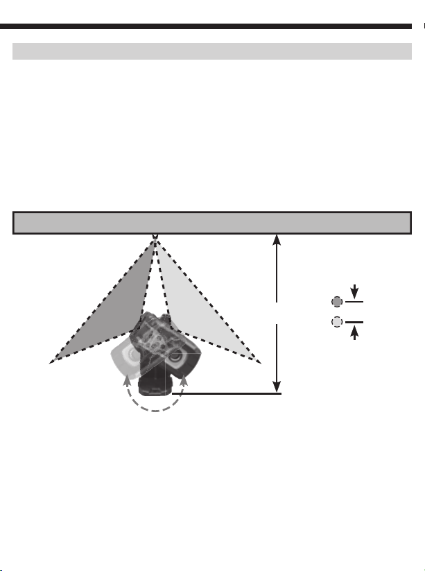
PENDULUM SLIDER SWITCH & SELF-LEVELING
The laser assemblies are mounted on a pendulum so that the instrument can self-level. The
Pendulum Slider Switch
6
must be in the unlocked position for the instrument to self-
level. If the instrument is tilted by >4°from the horizontal plane, the pendulum will not be
capable of self-leveling; the active laser beams will flash and the Excessive Tilt Indicator
5
will blink to indicate that the instrument is not level and cannot self-level. The instrument
must be repositioned on a more level geometry for the self-Leveling pendulum to function
appropriately.
NOTE: If the instrument indicates that it is not level
(via flashing beams and/or a blinking Excessive Tilt
indicator
5
),
then it should not be used for laying
out level or plumb lines.
NOTE: Following use, the active laser beams must be
turned OFF and the Pendulum Slider Switch must be
placed in the Locked position prior to storage.
InstrumentInstrument TiltedTilted ExcessivelyExcessively
Horizontal Laser LineHorizontal Laser Line Vertical Laser LineVertical Laser Line Plumb Laser LinePlumb Laser Line

6
ENGLISH
OPERATING INSTRUCTIONS
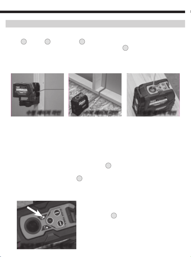
MAGNETIC MOUNTING BRACKET 14
The instrument is attached to a magnetic mounting bracket. The bracket may be
magnetically attached to any magnetic structure such as steel studs, ducts, structural
beams, and steel doors. The bracket also features a key-hole for mounting the instrument
using a screw or nail to non-magnetic structures. Once mounted to a structure via the
mounting bracket the instrument can be rotated on the bracket through 360°to direct the
laser beams.
CLAMP-ON WALL ADAPTER 16
The clamp-on wall adapter may be clamped to a structural beam, or wall bracket for
suspended ceiling installations, to present a steel surface onto which the instrument's
magnetic mounting bracket may be attached. Once magnetically attached the instrument
may be positioned to deliver the laser line at the required location. The clamp-on adapter
also features a key-hole for mounting the instrument using a screw or nail.
Mounted via keyholeMounted via keyholeMounted via magnetMounted via magnet
Adapter mounted on ceiling bracketAdapter mounted on ceiling bracket Adapter mounted via keyholeAdapter mounted via keyhole
7
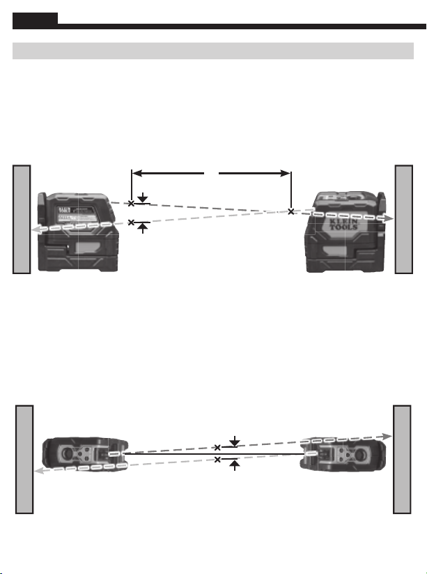
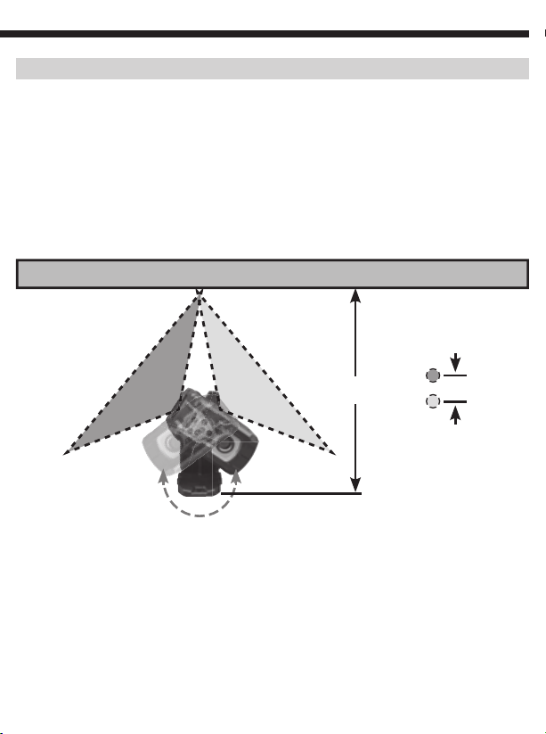
VERIFYING ACCURACY OF LASER LINES
Horizontal Beam Left/Right Tilt
Secure instrument via its mounting bracket at a distance xfrom a vertical wall structure as shown.
Rotate the instrument on the bracket to the left so that the right side of the beam is projected on the
wall directly across from the instrument, mark the vertical location on the wall. Rotate the instrument
to the right and repeat marking the vertical location of the left side of the beam. At ~33' (10 m) the
vertical distance dbetween the left-side and right-side markings should be ≤ 5/32" (4 mm). For
example, if xis set to 15' (4.6 m), the vertical distance dshould be ≤3/32" (2 mm).
WALL
Vertical distance
between markings
Right
Left
d
L
L
x
R
R
8
ENGLISH
VERIFYING ACCURACY OF LASER LINES
Vertical Beam Tilt
Position the instrument on the floor and project a vertical beam along a line xof about 6'
(1.9 m). Mark point a on the ceiling. Position the instrument on the other side of the line
and repeat marking point bon the ceiling. The distance dshould be ≤5/32" (4 mm) for a
33' (10 m) ceiling or ≤3/32" (2 mm) for a 15' (4.6 m) ceiling.
x
d
a
b
WALL
WALL
Horizontal Beam Out-of-Plane Tilt
Position the instrument parallel to a wall and project a beam along the wall, from left to right as
shown. Mark two locations (a, b) along the beam separated by distance x. Position the laser at
the other side of the wall and project the beam back through mark b, from right to left as shown,
and mark position c. If x is 30' (9.1 m), then the vertical distance dshould be ≤ 5/32" (4 mm). For
example, if xis set to 15' (4.6 m), then the vertical distance dshould be ≤ 3/32" (2 mm).
d
a
b
c
x
WALL
WALL

9
VERIFYING ACCURACY OF LASER LINES
Plumb Spot
Position instrument on the floor and project a spot with the plumb spot laser to the ceiling.
Rotate the laser by 180°and project the exact same spot to the ceiling. The distance d
should be ≤1/4" (6mm) for a 33' (10m) ceiling or ≤1/8" (3mm) for a 15' (4.6m) ceiling.
CEILING
d
180°

10
ENGLISH
BASED ON: 1390349 Rev 12/21 B
CLEANING
Be sure laser level is turned off and wipe with a clean, dry lint-free cloth.
Do not use
abrasive cleaners or solvents.
STORAGE
Remove the batteries when the instrument is not in use for a prolonged period of time.
Do not expose to high temperatures or humidity. After a period of storage in extreme
conditions exceeding the limits mentioned in the General Specifications section, allow the
laser level to return to normal operating conditions before using.
FCC AND IC COMPLIANCE
See this product’s page at www.kleintools.com for FCC compliance information.
Canada ICES-003 (B) / NMB-003 (B)
WARRANTY
www.kleintools.com/warranty
DISPOSAL /RECYCLE
Do not place equipment and its accessories in the trash. Items must be
properly disposed of in accordance with local regulations. Please see
www.epa.gov/recycle for additional information.
CUSTOMER SERVICE
KLEIN TOOLS, INC.
450 Bond Street Lincolnshire, IL 60069 1-800-553-4676
[email protected] www.kleintools.com
MAINTENANCE
BATTERY REPLACEMENT
When the Low Battery indicator
4
is illuminated red,
the batteries must be replaced.
1. Open the battery compartment door
11
.
2. Remove and recycle three spent AA batteries.
3. Install new batteries (note proper polarity).
4. Close battery compartment,
ensuring that it is securely shut.
한국어

사용 설명서
93LCLG
적색 다림줄 기능이 있는 녹색 셀프
레벨링 크로스 라인 레이저 레벨
한국어
• 수평 및수직
크로스 라인
• 다림줄 기능
93LCLG
IP54

12
한국어
일반 사양
Klein Tools 93LCLG는수평 및/또는 수직 크로스 라인 및/또는 장비 바로 위/아래에
다림줄 기능을 제공하여 정렬 및레이아웃 애플리케이션을 제공할 목적으로 사용할
수있는 셀프 레벨링 레이저 정렬 장비입니다.
• 작동 고도: 6562 피트(2000m)
• 상대 습도: <80% 비응축
• 작동 온도: 20°F ~ 115°F (-10°C ~ 45°C)
• 보관 온도: -5°F ~ 140°F (-20°C ~ 60°C)
• 레이저:• 515-530 nm(크로스 라인)
• 630-680 nm(다림줄 기능)
• 각빔≤1mW, Class II 레이저 제품
• 정확성: 33' 당±3/32"(10m 당±2mm) 수직 및수평 빔
33' 당±1/8"(10m 당±3mm) 상향 다림줄
33' 당±5/32"(10m 당±4mm) 하향 다림줄
• 배터리 유형: 3 x 1.5V AA 알카라인
• 치수: 5.3" x 5.0" x 2.8" (134 x 127 x 65 mm)
• 중량: 배터리 제외 26온스(820g)
• 보정: 1년간 정확함
• 표준: 준수 사항: EN61326-1:2013, EN60825-1:2014.
2019년5월8일자 Laser Notice No. 56에설명된 바와 같이,
IEC 60825-1 Ed. 3., 준수를 제외하고 21 CFR 1040.10 및1040.11 준수.
• 유입 보호: IP54 방진 및방수
• 전자기 환경: IEC EN61326-1:2013. 본장비는 주거지, 사무 시설 및경공업 현장
등과 같은 기본 및통제된 전자기 환경에서 사용하기 위한 요건을 충족합니다.
사양은
변경될
수
있습니다
.
13
경고
장비의 안전한 작동 및서비스를 보장할 수있도록, 다음 지침을 따르십시오. 이러한
경고를 따르지 않으면 심각한 개인 부상, 화재 또는 감전이 발생할 수있습니다. 나중에
참조할 수있도록 본지침서를 보관하십시오.
경고: 레이저 방사. 빔을 주시하지 마십시오. Class II 레이저.
•
레이저
방사선에
눈을
노출시키면
심각하고
영구적인
눈
부상을
입을
수
있습니다
.
절대로
이
장비에서
방출되는
레이저
빔을
직접
쳐다보지
마십시오
.
•
손상된
것처럼
보이는
장비를
사용하지
마십시오
.
•
심각한
눈
부상을
초래할
수
있는
위험한
레이저
방사선을
방출할
수
있으므로
어떤
식으로든
장비를
개조하지
마십시오
.
•
렌즈
,
프리즘
,
광학
스코프
등과
같은
광학
장비를
사용하여
레이저
빔을
전송
,
재전송
또는
주시하면
심각한
눈
부상을
초래할
수
있습니다
.
•
교육을
받지
않은
작업자
또는
지침을
읽고
완전히
이해하지
못한
작업자가
본
제품을
사용해서는
안
됩니다
.
•
본
제품은
심각한
눈
부상을
초래할
수
있으므로
다른
사람이
레이저
빔을
보거나
실수로
다른
사람의
눈에
조사할
수
있는
위치에서
사용해서는
안
됩니다
.
•
심각한
눈
부상을
초래할
수
있는
위험한
레이저
방사선에
실수로
노출될
위험을
최소화할
수
있도록
사용
후에는
장비의
전원을
꺼야
합니다
.
•
심각한
부상을
초래할
수
있고
위험한
레이저
조사에
노출될
위험이
증가할
수
있으므로
이
장비에서
경고
라벨을
제거하지
마십시오
.
•
예기치
않은
낙하
또는
장비의
이동으로
인해
장비가
손상될
수
있고
레이저
방사선에
우발적으로
노출되어
심각한
눈
부상이
발생할
위험이
증가할
수
있으므로
작동
전에
장비를
깔끔한
작업
환경에
안전하게
배치해야
합니다
.
•
장비는
IP54
방진
및
방수
기능을
갖추고
있습니다
.
물에
닿은
후에는
보풀이
없는
마른
천으로
장비를
완전히
건조시키십시오
.
•
장비
내부에는
사용자가
수리할
수
있는
부품이
없습니다
.
93LCLG 측면의
경고 라벨
14
한국어
7. 레이저를 사용한 다림줄 기능
8. 수평 라인 조리개
9. 수직 라인 조리개
10. 다림줄 기능 조리개
1. 수평선 켜기/끄기 버튼 11. 배터리 보관함 도어
2. 수직선 켜기/끄기 버튼 12. 1/4-20 삼각대 마운트
3. 수직점 켜기/끄기 버튼 13. 5/8-11 측량 삼각대 마운트
4. 배터리 부족 표시기 14. 마그네틱 마운트 브래킷
5. 과도한 경사 표시기 15. 자석
6.
전원/다림줄 잠금/잠금 해제 스위치
16. 클램프온 월어댑터
기능 세부사항
참고: 장비 내부에는 사용자가 수리할 수있는 부품이 없습니다.
장비의 기호
수직 레이저 라인(녹색)배터리 부족 표시기 유입 보호 IP54 등급 - 방진 및방수
수평 레이저 라인(녹색)과도한 경사 표시기 위험한 레이저 방사
수직 다림줄 레이저(적색)배터리 극성 경고 또는 주의
WEEE: 전자제품 폐기
Conformité Européenne:
유럽경제구역
지침
준수
UKCA:
영국
적합성
평가
레이저 Class 2 빔을 주시하거나 광학 기기를
직접 바라보지 마십시오.
지시
사항
숙독
윗면
옆면
뒷면
아랫면
14
15 2
6
7
8
5
10
31
9
4
1213
16 11
15
작동
지침서
레이저 빔켜기/끄기
수평선
1
, 수직선
2
, 다림줄 기능
3
의켜기/끄기 버튼을 눌러 각레이저 라인을 켜고
끕니다. 이버튼은 다림줄 잠금/잠금 해제 슬라이더 스위치
6
가잠금 해제 위치로 설정된
경우에만 활성화됩니다. 레이저 빔이 활성화되어 있는 동안 다림줄 슬라이더 스위치를
잠금 해제에서 잠금 위치로 전환하면 꺼집니다. 다른 레이저 라인은 독립적으로 또는
동시에 작동할 수있습니다.
참고: 다림줄 기능 애플리케이션은 위쪽 및아래쪽 방향 모두로 레이저 빔을 주사합니다.
하향 빔은 바닥 레이아웃에서 특정 지점을 찾을 때사용될 수있으며 상향 빔은 동일한
지점을 천장에 주사합니다.
다림줄 슬라이더 스위치 및셀프 레벨링
레이저 어셈블리는 다림줄에 장착되어 장비가 자체 수평을 유지할 수있습니다. 장비가
자체 수평을 유지하려면 다림줄 슬라이더 스위치
6
가잠금 해제 위치에 있어야 합니다.
장비가 수평면에서 >4°기울어지면 자체는 자체 수평을 맞출 수없습니다. 활성 레이저
빔이 점멸하고 과도한 경사 표시기
5
가점멸하면서 장비가 수평이 아니며 자체 수평을
맞출 수없음을 나타냅니다. 셀프 레벨링 다림줄이 적절하게 작동하려면 장비를 더
평평한 모양에 재배치해야 합니다.
참고: 장비가 수평이 아니라고 표시하는
경우(깜박이는 빔및/또는 깜박이는 과도한 경사
표시기를 통해
5
),
수평 라인 또는 다림줄 라인에
사용해서는 안됩니다.
참고: 사용 후에는 활성 레이저 빔을 끄고
다림줄 슬라이더 스위치를 잠금 위치에 놓고
보관해야 합니다.
장비가
장비가
지나치게
지나치게
기울어짐기울어짐
수평
레이저
라인수평
레이저
라인 수직
레이저
라인수직
레이저
라인 다림줄
레이저
라인다림줄
레이저
라인

16
한국어
작동 지침서
마그네틱 장착 브래킷 14
장비는 마그네틱 장착 브래킷에 부착됩니다. 브래킷은 강철 스터드, 덕트, 구조용 빔및
강철 문과 같은 모든 자성 구조물에 자석처럼 부착될 수있습니다. 나사나 못을 사용하여
비자성 구조물에 장비를 장착할 수있도록 브래킷에 키구멍도 있습니다. 장착 브래킷을
통해 구조물에 장착된 장비는 브래킷에서 360°회전하여 레이저 빔을 보낼 수있습니다.
클램프온 월어댑터 16
클램프온 월어댑터는 구조용 빔또는 달반자 설치용 벽브래킷에 클램프되어 강철
표면을 제공하는데, 이것은 장비의 마그네틱 장착 브래킷이 부착될 수있습니다.
자석으로 부착되면 필요한 위치에 레이저 라인을 전달하도록 장비를 배치할 수
있습니다. 또한, 클램프온 어댑터에는 나사나 못을 사용하여 장비를 장착하기 위한
키구멍도 있습니다.
키홀을
통해
장착키홀을
통해
장착자석을
통해
장착자석을
통해
장착
천장
브래킷에
장착된
어댑터천장
브래킷에
장착된
어댑터 키홀을
통해
장착된
어댑터키홀을
통해
장착된
어댑터
17
레이저 라인의 정확도 확인
수평 빔왼쪽/오른쪽 기울기
그림과
같이
수직
벽
구조로부터
x
거리에서
장착
브래킷을
통해
장비를
고정합니다
.
빔의
오른쪽이
장비
맞은편의
벽에
투사되도록
브래킷의
장비를
왼쪽으로
회전하고
벽에
수직
위치를
표시합니다
.
장비를
오른쪽으로
회전하고
,
반복해서
빔
왼쪽의
수직
위치를
표시합니다
. ~33'(10m)
에서
왼쪽과
오른쪽
표시
사이의
수직
거리
d
는
≤ 5/32"(4mm)
여야
합니다
.
예를
들어
, x
가
15'(4.6m)
로
설정된
경우
수직
거리
d
는
≤3/32"(2mm)
여야
합니다
.
벽
표시 사이의
수직
거리
오른쪽
왼쪽
LR
LR
x
d

18
한국어
레이저 라인의 정확도 확인
수평
빔
평면외
기울기
그림과
같이
장비를
벽과
평행하게
배치하고
왼쪽에서
오른쪽으로
벽을
따라
빔을
투사합니다
.
거리
x
로
분리된
빔을
따라
두
위치
(a, b)
를
표시합니다
.
레이저를
벽
반대편에
놓고
그림과
같이
오른쪽에서
왼쪽으로
b
표시를
통해
빔을
다시
투사하고
,
위치
c
를
표시합니다
. x
가
30'(9.1m)
인
경우
,
수직
거리
d
는
≤ 5/32"(4mm)
여야
합니다
.
예를
들어
, x
가
15'(4.6m)
로
설정된
경우
수직
거리
d
는
≤3/32"(2mm)
여야
합니다
.
벽
벽
b
x
d
a
c
수직 빔기울기
장비를 바닥에 놓고 약6'(1.9m)의라인 x를따라 수직 빔을 투사합니다. 천장에 a지점을
표시합니다. 라인의 반대쪽에 장비를 놓고 천장에 b지점을 반복해서 표시합니다.
거리 d는33'(10m) 천장의 경우 ≤5/32"(4mm) 또는 15'(4.6m) 천장의 경우
≤3/32"(2mm)여야 합니다.
벽
벽
x
d
a
b

19
레이저 라인의 정확도 확인
다림줄 기능
장비를 바닥에 놓고 다림줄 기능 레이저로 천장에 한지점을 투사합니다. 레이저를 180°
회전하고 정확히 동일한 지점을 천장에 투사합니다. 거리 d는33'(10m) 천장의 경우
≤1/4"(6mm) 또는 15'(4.6m) 천장의 경우 ≤1/8"(3mm)여야 합니다.
천장
d
180°

20
한국어
기준: 1390349 Rev 12/21 B
청소
레이저 레벨이 꺼져 있는지 확인하고 보풀이 없는 깨끗한 천으로 닦으십시오.
연마성 세제나 솔벤트를 사용하지 마십시오.
보관
장비를 장기간 사용하지 않는 경우, 배터리를 제거하십시오. 고온이나 습기에
노출시키지 마십시오. 일반 사양 섹션에 명시된 제한을 초과한 극한의 조건에서 보관된
경우, 사용 전에 레이저 레벨이 정상 작동 상태로 돌아갈 수있도록 하십시오.
FCC 및IC 준수
FCC 규정 준수 정보는 www.kleintools.com에서 제품 페이지를 참조하십시오.
Canada ICES-003 (B) / NMB-003 (B)
보증
www.kleintools.com/warranty
폐기/재활용
장비 및액세서리를 휴지통에 버리지 마십시오. 품목은 지역 규정에 따라
적절하게 폐기되어야 합니다. 자세한 내용은 www.epa.gov/recycle을
참조하십시오.
고객 서비스
KLEIN TOOLS, INC.
450 Bond Street Lincolnshire, IL 60069 1-800-553-4676
[email protected] www.kleintools.com
유지보수
배터리 교체
배터리
부족
표시기
4
가
빨간색으로
켜지면
배터리를
교체해야
합니다
.
1. 배터리 보관함 도어
11
를엽니다.
2. 사용한 3개의 AA 배터리는 꺼내서 재활용하십시오.
3. 새배터리를 설치합니다(적절한 극성에 주의).
4. 배터리 보관함을 닫고 제대로 잠겨 있는지 확인합니다.
日本語
Other manuals for 93LCLG
1
Table of contents
Languages:
Other Klein Tools Laser Level manuals

Klein Tools
Klein Tools 93PLL User manual

Klein Tools
Klein Tools 93LCLS User manual

Klein Tools
Klein Tools 93LCL User manual

Klein Tools
Klein Tools 93LCLG User manual

Klein Tools
Klein Tools 93LCLGR User manual

Klein Tools
Klein Tools 93PLL User manual

Klein Tools
Klein Tools LBL100 User manual

Klein Tools
Klein Tools 93LCL User manual
Popular Laser Level manuals by other brands


EINHELL
EINHELL 22.701.05 operating instructions

Dinel
Dinel RFLS-53N instruction manual

Black & Decker
Black & Decker BullsEye BDL190S instruction manual

CST/BERGER
CST/BERGER LM800DP Original instructions

ADA INSTRUMENTS
ADA INSTRUMENTS 3D Liner 2V Green operating manual

protech
protech 3241PTL02 instruction manual