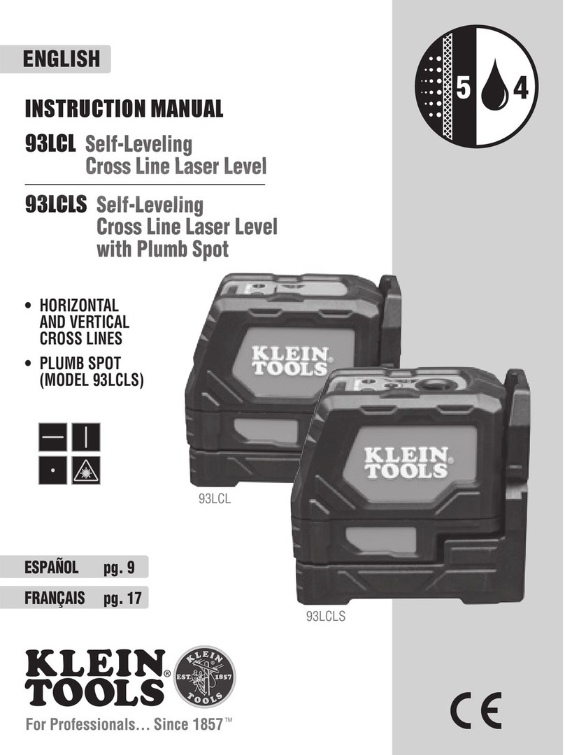
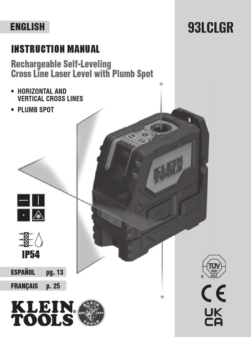
Klein Tools 93LCL User manual

Horizontal Beam Out-of-Plane Tilt (FIG. 2)
Position the instrument parallel to a wall and project a beam along the wall, from
left to right as shown. Mark two locations (a, b) along the beam separated by distance x.
Position the laser at the other side of the wall and project the beam back through mark
b, from right to left as shown, and mark position c. If x is 30' (9.1 m), then the vertical
distance dshould be ≤ 5/32" (4 mm).
For example,
if xis set to 15' (4.6 m), then the
vertical distance dshould be ≤ 3/32" (2 mm).
Horizontal Beam Left/Right Tilt (FIG. 1)
Secure instrument via its mounting bracket at a distance xfrom a vertical wall
structure as shown. Rotate the instrument on the bracket to the left so that the right
side of the beam is projected
on the wall directly across
from the instrument, mark
the vertical location on the
wall. Rotate the instrument
to the right and repeat
marking the vertical location
of the left side of the beam.
At ~33' (10 m) the vertical
distance dbetween the
left-side and right-side
markings should be ≤ 5/32" (4 mm).
For example, if xis set to 15' (4.6 m),
the vertical distance dshould be ≤3/32" (2 mm).
FIG. 2
d
a
b
c
x
WALL
WALL
FIG. 1
WALL
Vertical distance
between markings
Right
Left
d
L
L
x
R
R
R
Vertical Beam Tilt (FIG. 3)
Position the instrument on the floor and project a vertical beam along a line xof
about 6' (1.9 m). Mark point a on the ceiling. Position the instrument on the other
side of the line and repeat marking point bon the ceiling. The distance dshould be
≤5/32" (4 mm) for a 33' (10 m) ceiling or ≤3/32" (2 mm) for a 15' (4.6 m) ceiling.
FIG. 3
x
d
a
WALL
WALL
CEILING
Plumb Spot (Model 93LCLS Only, FIG. 4)
Position instrument on the floor and
project a spot with the plumb spot laser
to the ceiling. Rotate the laser by 180°and
project the exact same spot to the ceiling.
The distance dshould be ≤1/4" (6mm) for
a 33' (10m) ceiling or ≤1/8" (3mm) for a
15' (4.6m) ceiling.
d
FIG. 4
b
180°
VERIFYING ACCURACY OF LASER LINES
93LCL
Self-Leveling Cross Line Laser Level
93LCLS
Self-Leveling Cross Line Laser Level with Plumb Spot

VERIFICAR LOS HACES DEL LÁSER PARA COMPROBAR LA PRECISIÓN DEL NIVEL
Inclinación fuera de plano del haz horizontal (FIG. 2)
Posicione el instrumento paralelo a una pared y proyecte un haz a lo largo de la pared,
de izquierda a derecha, como se muestra en la figura. Marque las dos ubicaciones (a,
b) del haz separadas por al distancia x. Posicione el láser en el otro lado de la pared y
proyecte el haz hacia la marca b, de derecha a izquierda, como se muestra, y marque
las posición c. Si x es 30' (9,1m), la distancia vertical ddebe ser ≤ 5/32" (4mm). Por
ejemplo, si xse establece en 15' (4,6m), la distancia vertical ddebe ser ≤ 3/32" (2mm).
Inclinación del haz horizontal hacia la izquierda/derecha (FIG. 1)
Fije el instrumento mediante el soporte a una distancia xdesde una estructura o pared vertical,
como se muestra. Rote el instrumento sobre el soporte hacia la izquierda para que el lado
derecho del haz se proyecte sobre
la pared directamente en frente
del instrumento, marque la
ubicación vertical en la pared.
Rote el instrumento hacia la derecha
y repita la marca de la ubicación vertical
del lado izquierdo del haz.
A ~33' (10m), la distancia vertical
dentre las marcas del lado
izquierdo y el lado derecho
debe ser ≤ 5/32" (4mm).
Por ejemplo, si xse establece en 15', (46m),
la distancia vertical ddebe ser ≤3/32" (2mm).
FIG. 1
PARED
Distancia vertical
entre las marcas
Derecha
Izquierda
d
Izq.
Izq.
x
FIG. 2
d
a
b
c
x
PARED
PARED
Der.
Der.
Der.
Inclinación del haz vertical (FIG. 3)
Coloque el instrumento sobre el piso y proyecte el haz vertical a lo largo de una línea xde
aproximadamente 6' (1,9m). Marque el punto a en el cielo raso. Coloque el instrumento
en el otro lado del línea y repita el punto de la marca ben el cielo raso. La distancia d
debe ser ≤5/32" (4mm) para un cielo raso de 33’ (10m) o ≤3/32" (2mm) para un cielo
raso de 15' (4,6m).
FIG. 3
x
d
a
PARED
PARED
CIELO RASO
Punto de plomada
(solo modelo 93LCLS, FIG. 4)
Coloque el instrumento sobre el piso y
proyecte un punto con el láser de punto
de plomada hacia el cielo raso. Rote el
láser 180°y proyecte el haz del láser
sobre exactamente el mismo punto en el
cielo raso. La distancia ddebe ser ≤1/4"
(6mm) para un cielo raso a 33" (10m)
o ≤1/8" (3mm) para un cielo raso a 15'
(4,6m).
d
FIG. 4
b
180°
93LCL
Nivel láser autonivelante de líneas en cruz
93LCLS
Nivel láser autonivelante de líneas en cruz y punto de plomada

VÉRIFICATION DES FAISCEAUX LASER À DES FINS DE PRÉCISION DU NIVEAU
Inclinaison hors plan du faisceau à l’horizontale (FIG. 2)
Placez l’instrument parallèlement au mur et projetez un faisceau le long du mur,
de gauche à droite, tel qu’illustré. Marquez deuxemplacements (a, b) séparés par une distance
xle long du faisceau. Placez le laser de l’autre côté du mur et projetez le faisceau avec la
marque b, de la droite vers la gauche tel qu’illustré. Finalement, marquez la position c. Si x est
de 9,1m (30pi), la distance verticale ddevrait correspondre à 4mm (≤5/32po). Par exemple,
si xest fixé à 4,6m (15pi), la distance verticale ddevrait correspondre à 2mm (≤3/32po).
Inclinaison vers la gauche/droite du faisceau à l’horizontale (FIG. 1)
Stabilisez l’instrument avec son support de fixation à une distance xpar rapport à la structure
murale verticale, tel qu’illustré. Faites tourner l’instrument sur son support vers la gauche de
façon à ce que le côté droit du
faisceau soit projeté sur le mur
opposé à l’instrument, puis
marquez son emplacement
vertical sur le mur. Faites tourner
l’instrument vers la droite et
marquez l’emplacement vertical
du côté gauche du faisceau.
À environ 10m (33pi), la
distance verticale dentre les
marques du côté gauche et du
côté droit devrait être ≤4mm (5/32po).
Par exemple, si xest fixé à 4,6m (15pi),
la distance verticale ddevrait correspondre
à 2mm (≤3/32po).
FIG. 1
MUR
Distance verticale
entre
les marques
Droite
Gauche
d
G
G
x
FIG. 2
d
a
b
c
x
MUR
MUR
D
D
Inclinaison verticale du faisceau (FIG. 3)
Posez l’instrument au plancher et projetez un faisceau vertical sur une ligne
xd’environ 1,9m (6pi). Marquez le point a au plafond. Placez l’instrument de
l’autre côté de la ligne et marquez de nouveau le point bau plafond. La distance
ddevrait atteindre 4mm (≤5/32po) pour un plafond de 10m (33pi), ou alors
2mm (≤3/32po) pour un plafond de 4,6m (15pi).
FIG. 3
x
d
a
MUR
MUR
PLAFOND
Plomb
(MODÈLE93LCLS seulement, FIG. 4)
Posez l’instrument sur le plancher et projetez
une cible au plafond avec le laser à plomb.
Faites tourner le laser sur 180°et projetez
cette même cible au plafond. La distance
ddevrait atteindre 6mm (≤1/4po) pour
un plafond de 10m (33pi), ou alors 3mm
(≤1/8po) pour un plafond de 4,6m (15pi).
d
FIG. 4
b
180°
93LCL
Niveau laser en croix à nivellement automatique
93LCLS
Niveau laser en croix à nivellement automatique à plomb
1390235 Rev. 05/17 B
Other manuals for 93LCL
1
This manual suits for next models
1
Table of contents
Languages:
Other Klein Tools Laser Level manuals

Klein Tools
Klein Tools 93LCLG User manual

Klein Tools
Klein Tools LBL100 User manual

Klein Tools
Klein Tools 93PLL User manual

Klein Tools
Klein Tools 93LCL User manual

Klein Tools
Klein Tools 93LCLGR User manual

Klein Tools
Klein Tools 93LCLS User manual

Klein Tools
Klein Tools 93LCLG User manual

Klein Tools
Klein Tools 93PLL User manual