Klever Y Muse 25 User manual

NL November 2021
Model
User manual
Klever Y Muse 25
km/h

www.klever-mobility.com 3
Contents
Contents
. QuickStart ..............................................................................................................................
. Introduction ............................................................................................................................
. EC Declaration of Conformity CE.............................................................................................
. Getting started and safety check of your Y Muse ..................................................................
. Behaviour in road trac ........................................................................................................
. Klever’s proprietary propulsion the BIACTRONsystem ..........................................................
. Sensors and their function....................................................................................................
. Levels of electric motor support ............................................................................................
. Regeneration of battery capacity..........................................................................................
. Display ................................................................................................................................
... Function of each button ...................................................................................................
... Display content................................................................................................................
... Settings of the menu and the submenu’s ...........................................................................
. Rechargeable battery...........................................................................................................
.. Charging the battery .........................................................................................................
.. Range ..............................................................................................................................
.. Removing and mounting of the battery..............................................................................
.. Transport of the battery ....................................................................................................
. Diagnostics and troubleshooting of the electric system..........................................................
. Bicycle parts of the Y Muse .................................................................................................
. Adjustment of saddle and handlebar .....................................................................................
. The suspension front fork .....................................................................................................
. Disc brakes ..........................................................................................................................
. Mechanical drive train and gearshift .....................................................................................
. Lighting...............................................................................................................................
. Wheels and tyres..................................................................................................................
.Luggage carrier and transport of luggage...............................................................................
. Theft protection...................................................................................................................
. Accessories..........................................................................................................................
. Child seat ..........................................................................................................................
. bicycle trailer .....................................................................................................................
. Transport of your Y Muse ....................................................................................................
. Maintenance, care and storage...............................................................................................
. Disposal and transportation .................................................................................................
. Technical data......................................................................................................................
. Product liability and warranty...............................................................................................
. Intended use of your Y Muse .............................................................................................

www.klever-mobility.comwww.klever-mobility.com4 5
Contents QuickStart
. QuickStart
Dear customer,
On the first pages of this comprehensive instruction manual,
you will find this QuickStart guide which gives you a quick
overview of the main features of the Y Muse 25 e-bike.
For further information please read the additional
instructions on the following pages. There you will find all
important technical details and further relevant information.
Should you have any further questions, please ask one of our
authorised dealers or contact our technical hotline, whose
contact details are at the end of the manual.
Enjoy your Y Muse 25 e-bike and we wish you a lot of fun,
The Klever Mobility team.
Image 1
. Wear ...................................................................................................................................
. Legal requirements for participation in trac on public roads.................................................
. Regular maintenance and inspection ....................................................................................
. FAQ’s...................................................................................................................................
. Bicycle passport...................................................................................................................
. Inspection plan ....................................................................................................................
. Imprint................................................................................................................................

www.klever-mobility.comwww.klever-mobility.com6 7
LED
E-KEY
QuickStartQuickStart
Charging the battery:
Caution! The battery should only be charged with the
appropriate, supplied charger (image 4).
The battery can be charged on (image 6A) and o bike (image
6B). For removal of the battery see section 6.5.3.
Connect the charger with the power cable and the power
plug to the wall socket. If the LED on the charger shows
constant red light, the charger is ready for use. Connect the
charger plug of the charger to the charging socket on the
battery (images 4+5+6A/6B). The charging process starts
automatically. Once the LED on the charger constantly lights
green the operation is complete and the battery is charged.
Unplug the power plug from the wall first, then remove the
charger lead from the battery charger.
Charging
status
LED on charger LED on battery pack Remark
Flashing red Error code: check connections
Steady red Charger is ready to charge
0% Flashing yellow Flashing red Capacity very low; charging starts
<35% Steady yellow Flashing red Normal charging
35 – 75% Steady yellow Flashing yellow Normal charging
75 – 90% Steady yellow Flashing green Normal charging
>90% Flashing green Flashing green Final charging
100 % Steady green No LED colour
Fully charged
The charging of an empty rechargeable battery of 570 Wh (from 0% to 96%) will take about 7 hours
with the standard 2A charger.
Safety check
Before starting the bike please always check the operation of
the brakes and the tyre pressure.
Launch of the electric drive
You can start the system with or without inserting the dedicatedY
Muse 25 E-KEY(image 2). Check for the details concerning the function
of the E-KEYsection 6.4.
As soon as you insert the E-KEYinto the display,the system will be
activated and start itself.With the E-KEYalready in the display while the
system is off, there are two ways to activate the system:
1. Just press the on/o button (image 3), after a 3 seconds
system check your E-bike is ready to be pedalled.
2. When you start pedalling, the electric system will
wake up automatically. After a 3 seconds system check, the
electric drive will start to support.
NNo support, electric
system active
ECO Low support
TOUR Medium support
MAX High support
The á(TURBO) button on the display has 3 functions:
1. Walk-assist: actuate the á(TURBO) button while
walking next to your E-bike. The maximum speed is 4
km/h.
<4 km/h Pushing aid while
taking your E-bike by
the hand.
2. TURBO-mode WITHOUT pedalling of the cyclist.
The maximum speed is 4 km/h.
<4 km/h
Additional support at
standstill or in case you
do not want to pedal.
3. TURBO-mode WITH pedalling of the cyclist. While
actuating the á(TURBO) button in ECO- or TOUR-
mode the electric support will be increased to MAX-
mode.
<25 km/h Additional support
while riding hills or
strong headwinds.
Image 2
Image 3
Image 4
Image 5
Image 6B
Image 6A
Power plug
Power cable
Charger
Charging socket

www.klever-mobility.comwww.klever-mobility.com8 9
IntroductionIntroduction
a a bright-sounding horn, a complete lighting system with
quality marks for the head light and the tail light, reflectors
and with 2 sets of brakes independently actuating the front
and rear wheel.
Please note! The additional electric motor support is
limited to max. 25 km/h, and thus complies with the
statutory requirements for EPAC vehicles (Electrically
Pedal Assist Cycles). Meaning you do not need a liability
insurance, license plate nor a driving license. Moreover,
it is not mandatory to wear a helmet, even though we
strongly recommend to wear one for your own safety.
. Introduction
Congratulations
With the purchase of this Klever Mobility Y Muse 25 E-bike
you have made the right purchase decision and you got a
high-quality product which will offer a lot of pleasure in
everyday life.
Technically and functionally up to date, it is carefully
manufactured using the highest quality materials and
components. An excellent design and excellent value for
money distinguishes this E-bike.
For a trouble free, pleasurable riding experience with your
new Y Muse, please read this manual carefully.
Everything you need to know in terms of technical
specifications, operation, maintenance and care, has been
carefully compiled in this manual. Please also note the
additional information in the instructions separately
supplied with some of the components.
Pay particular attention to sections in bold which are
additionally marked with "Caution" symbol. The most
important information is again summarised. It should
be observed to avoid possible accidents and danger to
your life and limb.
Bold sections marked with this symbol contain
information about the Y Muse and its accessories and
its handling.
Operations marked with this symbol are to be executed
by authorised Klever dealers. These operations require a
lot of experience and special tools.
Furthermore, in case you need any further information or
advice, please contact our technical hotline at +31 (0)30
2102905 (Monday - Friday from 8h00 -17h00 CET), or contact
an authorised Klever retailer.
The latest available information on our products, other
technical information and videos can be found on our
website: www.klever-mobility.com.
Your Y Muse 25 E-bike has been equipped according to the
Belgian & Dutch Road Trac Act. Hence, you can use it
safely on public roads. This E-bike has been equipped with

www.klever-mobility.comwww.klever-mobility.com10 11
Getting started and safety check of your Y Muse 25EC Declaration of Conformity CE
. Getting started and safety
check of your Y Muse
Although your E-bike has been subject to a final check on
the assembly line as well as by your local Klever dealer,
the transport and time may have caused changes in
its functionality. Therefore, prior to your first ride and
occasionally thereafter, you should consider to check
following points:
• Make yourself intensely familiar with the Y Muse 25 and the
functioning of its electric motor support, before the first ride
in public trac.
• Setting of the saddle and the handlebars.
• Function of the brakes.
• Air pressure and the depth of the thread pattern of the tyres.
• Proper operation of the lighting system.
• Tightness of the bolts and nuts of the wheels.
• Minimum insertion of the seat post.
Caution! Do not start when you identify deficiencies in
one of these points. While riding a defective E-bike this
can cause serious accidents and endanger your life. If
in doubt, please contact your dealer or our technical
hotline.
Caution! Your bike suers wear and tear in everyday
riding through extreme weather and road bumps.
Through constant dynamic loads dierent parts of the
bike experience dierent material fatigue and wear.
Therefore, it is recommended to inspect your Y Muse 25
on a regular basis and look for wear of parts and changes
in scratches or cracks, or the discolouring of parts. These
could possibly indicate damage of the part. Needless to
say, that damaged parts must be repaired or replaced.
Please note! Following the inspection plan in section
19, you best bring your E-bike to your Klever dealer for
inspection, service, maintenance and repair.
. EC Declaration of Conformity CE
The Manufacturer:
Klever Mobility Inc.
No. 8, Ln.76, Sec.3, Zhongyang Rd.,
Tucheng Dist.; New Taipei City 236
Taiwan
Represented the Benelux by:
Klever Mobility NL bv
Regulierenring 15
3981 LA Bunnik
Tel.: +31 30 210 2905
infoNL@klever-mobility.com
www.klever-mobility.nl
Hereby confirms for the product: Y Muse 25 km/h model year
2021:
Conformity with all applicable directives from the European
Machinery directive: 2006/42/EC.
The machine also conforms to all the directives from the
Electromagnetic Compatibility directive: 2004/108/EC.
In addition, the following harmonised European Standards
apply: the EN 15194:2017 standard for bicycles with electric
pedal support (EPAC’s) and the EN-ISO 4210 standard for city
and touring bicycles in which the technical safety requirements
and test methods are being described.
Technical documentation by:
Klever Mobility NL bv

www.klever-mobility.comwww.klever-mobility.com12 13
Behaviour in road trafficGetting started and safety check of your Y Muse 25
. Behaviour in road trac
Thanks to the electric auxiliary propulsion you reach high
speeds and accelerate faster and easier than you are used
to with a regular bike. Therefore, you should intensively
familiarise yourself with the Y Muse only on a trac-calmed
road before you go in public trac. During riding on the road,
you should follow these tips:
• Though it is not compulsory, we strongly recommend to
always wear a helmet during riding.
• Make yourself familiar with the trac rules and stick to the
rules.
• Be ready to brake at any time and expect misconduct of
others.
• Ride defensively and be considerate to other road users.
• Always keep your Y Muse 25 in a perfect condition.
• Use your bike only in accordance with its intended purpose
(see section 13. Intended use).
• Don´t use a mobile phone nor a headset while riding.
• -Be sure to observe the maximum weight of cyclist + Y Muse
25 + luggage of 150 kg (see section 11. Technical Data).
• Have your E-bike checked according to the recommended
service intervals by authorised Klever dealers.
Please note! Make sure to only use original Klever spare
parts. In case you are not sure whether to use certain
spare parts or not, please always contact your ocial
Klever dealer or otherwise call our technical hotline.

www.klever-mobility.comwww.klever-mobility.com14 15
The BIACTRON systemThe BIACTRON system
The five (dierent) levels of motor support can be selected
according to the external circumstances (e.g., climbing uphill
or with headwind) or to your personal preferences. Please
note that a higher level of motor support consequently
means a higher battery consumption and reduces the range
of system and battery.
In case you ride faster than 35 km/h (e.g., downhill),
automatically the recuperation of pedal energy (i.e., technical
regeneration) will be activated. The motor operates as a
generator and partly re-charges the battery. The recuperation
of pedal energy and battery capacity = REGENERATION will
be explained in section 6.3.
.. Sensors and their function
The Y Muse 25 is equipped with a torque sensor in the frame’s
rear dropout. This sensor accurately measures
the force you exert during pedalling. In conjunction with
the pedal sensor, this torque sensor precisely monitors
the cycling eort of the cyclist. The motor controller then
calculates these values and manages precisely the amount of
support from the motor. Hence generating a perfect synergy
between cyclist and Y Muse 25.
You can also define the amount of motor support by yourself
choosing between the ascending levels of support (N, ECO,
TOUR, MAX, TURBO). This makes the system very ecient
and economic, saving power consumption and maximising
range.
The additional speed sensor sets the power of the electric
motor to zero once you have reached a speed of 25 km/h or
more. Above 25 km/h this E-bike functions like a conventional
bicycle, the only way to maintain the propulsion of the
vehicle is by pedalling solely.
The electric motor support only kicks in when you actively
pedal. Therefore, from a standstill to get started either you
have to pedal or you have to actuate the á(TURBO) button
on the display. From standstill without pedalling the motor
will take you to a maximum speed of 4 km/h. The á(TURBO)
button was also designed as an aid when starting uphill or in
case the bike has to be pushed while walking alongside the
bike.
. Klever’s proprietary electric
propulsion the BIACTRON
system
You have purchased an E-bike that helps you improve your day-
to-day mobility with its electric propulsion. Slopes can be better
managed and the wind resistance can be better overcome.
Klever’s electric BIACTRON system consists of the following
components:
1.Rechargeable battery
2.Motor
3.Control unit / Display
4.Motor controller
5.Torque sensor
6.Pedal Sensor
7.Charger (image 7)
Once you turn on the system and you start pedalling, the
motor will support you as long as you pedal up to a maximum
speed of 25 km/h.
Image 7
Image 8
front light
rear light
1. Battery
2. Motor
6. Pedal sensor
5. Torque sensor
4. Motor
controller
3. Display /
dashboard

www.klever-mobility.comwww.klever-mobility.com16 17
Please note! These 3 options will only function while
you keep the á(TURBO) button pushed. As soon as you
release the á(TURBO) button, the electric motor support
will stop. Except in the latter case of pedalling: in that
case after releasing the á(TURBO) button the level of
electric motor support will go back to the preselected
level (TOUR as in the example of scenario 3).
In order to save battery power, the support level will
automatically be limited to the TOUR level when the battery
capacity drops to 10%. When the battery capacity drops to 5%
the support level will be limited to the ECO level and in the
case of a battery capacity of 2% or less the level will be N.
. Recuperation of battery capacity:
regeneration
The BIACTRON system of your Klever electric bicycle has an
innovative, unique function: the recovery of battery capacity, also
known as regeneration. Every time the drive system goes into
freewheel mode, the BIACTRON system will start braking the
motor. As a consequence, the motor friction is being converted into
electricity that is stored in the battery.The freewheel model will be
activated once you do not pedal and roll out to a traffic light or you
roll down a hill or mountain without having to pedal.
Section 6.4.3 (menu for settings) explains how this function can
be activated and adjusted to your personal preferences.The
regeneration function is a nice and clean addition to the capacity,
consumption and range of your battery.The more and longer you
ride in a mountainous environment,the more you will benefit from
this function. However, the recovery of electricity is limited and
depends to a large extent on your riding behaviour, the environment
where you ride and the chosen regeneration settings.
. Levels of electric motor support
Our BIACTRON-system oers five levels of electric motor
support:
• N
• ECO
• TOUR
• MAX
• TURBO
Depending on topography, weather conditions and your
personal preferences, you can choose the motor support using
↑ (Up arrow) and ↓ (Down arrow) button and the á(TURBO)
button.
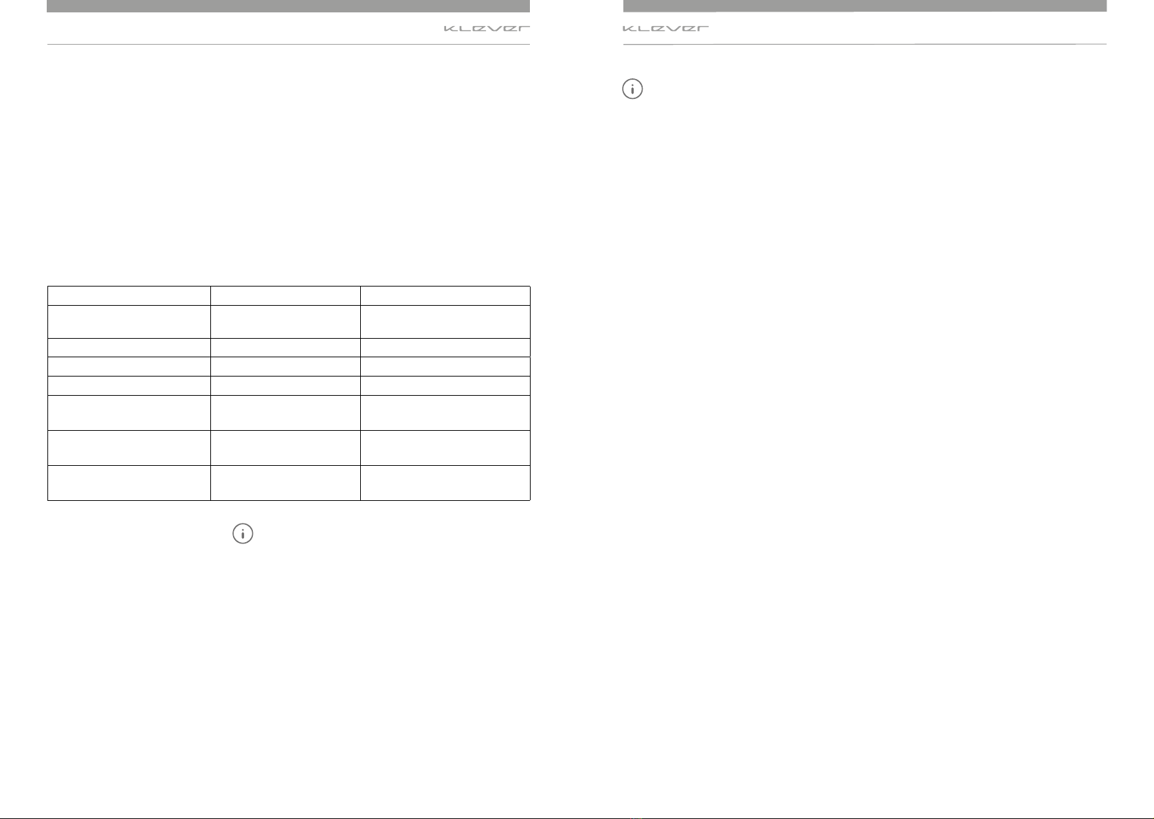
System level Amount of support
Situation (recommended)
N No support, electric system
active
Downhill
ECO Low support Flat roads
TOUR Medium support Slight hill / headwind
MAX Strongest support Steep hills / fierce headwinds
á(TURBO) (MAX) while
pedalling < 25 km/h.
Strongest support Steep ramps / violent gusts
á(TURBO) (MAX) without
pedalling < 4 km/h.
Strongest support Starting from standstill
áTURBO) (ECO) walking with Y
Muse < 4 km/h.
Walk-assist, low support Walking with Y Muse or pushing
uphill
Please note! In case you actuate the á(TURBO) button,
there are three scenarios:
1. You walk alongside the Y Muse and/or you push it out
of your garage. While pushing the á(TURBO) button you
will activate the Walk-assist mode and you will trigger
a moderate electricmotor support up to 4 km/h. In this
way you can walk with your vehicle comfortably and
easily.
2. You are sitting on your Y Muse 25 and intend to start
from standstill on a ramp without pedalling. Push the á
(TURBO) button and you will get the strongest support
up to 4 km/h.
3. You are sitting on your Y Muse 25. You are pedalling
with for instance TOUR support and you need the
strongest support momentarily. Push the á(TURBO)
button while pedalling and you will trigger the strongest
support regardless your speed (from 0 to 25 km/h).
The BIACTRON systemThe BIACTRON system

www.klever-mobility.comwww.klever-mobility.com18 19
Turbo (á)
( )
()
Info (•)
E-KEY
Display Display
Button Location Function
Power Upper left edge On/O system
INFO (•) Button with a dot, in bet-
ween the two arrows
Switch between time, trip, Km-day,
odo, soc (state of charge), kcal
(calories) and cadence
Up arrow (↑) Middle left Increase support level
Down arrow (↓) Lower left Reduce support level
áTurbo Lower left edge Starting and walking aid
(without pedalling)
Strongest support (without pedalling)
Strongest support (while pedalling)
Light Upper left panel On/Off light
.. Function of each button
On/O button (image 11)
Press the POWER button and you’ll boot the system. The
system performs a system check of 3 seconds, and the drive
system is ready to operate. The electric drive will start to
support depending on the level of assistance chosen.
Press this button again, the system will be turned o and all
settings are being stored. Press the button again, the system
starts and all previous settings and levels of support are
enabled again.
Up arrow (↑) button (image 12)
Press the up arrow (↑) button and you increase the support
level. For instance, when the selected level is TOUR and you
press the up arrow (↑) button, the support level of the motor
will increase to MAX level.
Down arrow (↓) button (image 13)
Press the down arrow (↓) button and you decrease the
support level. For instance, when the selected level is TOUR
and you press the down arrow (↓) button, the support level
of the motor will decrease to ECO level..
. Display
With the display you start and control the BIACTRON-system.
When you purchase the Y muse 25 your Klever dealer will pair
the e-bike with a set of two E-KEY’s with a unique ID code.
After the pairing your Y Muse 25 will only function and start
with E-KEY’s with the programmed ID code. It is impossible to
activate your Klever bike with an E-KEY of another bike. Each
Klever bike will be delivered with two identical E-KEY’s with
their unique ID code.
Now you can start the system with or without inserting
the E-KEY (see section 6.4.3).
Every press of a button will be confirmed with a short acoustic
signal. As soon as you insert the E-KEY into the display (image
10), the system will start. With the E-KEY already in the display
while the system is o, there are two ways to activate the
system:
1. Just press the On/O button (image 9), after a 3 seconds
system check your E-bike is ready to be pedalled.
2. When you start pedalling, the electric system will
wake up automatically. After a 3 seconds system check, the
electric drive will start to support.
Image 9
Image 11
Image 12
Image 13Image 10
Support level
details
Support
level name
High/low
beam lights
E-Key
indicator
Power
consumption
Regen power
General warnings
* Visit your dealer if the
warning signal continues to
appear on the displa
Bluetooth
Warning
icon
LIGHT
Power
ON/OFF
Battery
indicator
E-KEY port
Current
speed
D-Info

www.klever-mobility.comwww.klever-mobility.com20 21
DisplayDisplay
Trip (image 17)
The number of kilometres ridden since the last reset, in this
case 0.9 km. If you want to reset the trip distance to zero at
the start of a new trip, press the INFO (•) button long and
select ‘Reset’ in the menu. Select ‘yes’ and confirm by pressing
the INFO (•) button (see section 6.4.3 with the submenus of
the display settings).
Km-day (image 18)
Kilometres ridden today, starting at 00h00, in this case 3.5
km. The daily mileage will be set to zero at midnight 00:00
every day.
Odo (image 19)
Accumulated kilometres during the entire lifecycle of your Y
Muse 25, in this case 459 km. When the odo reaches 99,999 km.
it will be reset to 0.
SOC = State of Charge (image 20)
The SOC indicates the current battery capacity, in this case
49% of the total.
Kcal (image 21)
The rider’s number of kilocalories burnt while cycling, in
this case 12.0 kcal. For proper kcal calculation please set
the rider’s weight. Press the INFO (•) button long and select
‘Rider’ in order to input the rider’s weight. Kcal can be reset
by selecting RESET in the menu (see section 6.4.3 with the
submenus of the display settings).
INFO (•) button (image 14)
Press the INFO (•) button and subsequently all rider’s
information will be displayed on the LCD-screen.
Press the INFO (•) button shortly in order to go through the
available rider’s data: time, trip. Km-day, odo, soc, kcal and
cadence. See below.
Please note: the available rider’s data may vary depending on
bike model and software version
Time (hh:mm) (image 16)
The time can be adjusted in the settings menu of the display,
by synchronising with your smartphone or with the service
tool at your Klever dealer.
Image 14
Image 15
Image 16
Image 17
Image 18
Image 19
Image 20
Image 21
Press “INFO button” to
change the D-INFO

www.klever-mobility.comwww.klever-mobility.com22 23
DisplayDisplay
Cadence (image 22)
The cadence is the rider’s pedal frequency shown in rotations
per minute (RPM). In other words, it shows you how many
full rounds your pedals make per minute. In this case 59.
á(TURBO) button (image 23)
This button has three functions for three dierent scenarios
of á(TURBO) usage.
1. As a walk-assist while walking alongside your Y Muse.
2. As a á(TURBO) power assist without pedalling.
3. As a á(TURBO) power assist while pedalling.
Section 6.2 deals in detail with these three dierent scenarios.
Please note! We recommend that you familiarise yourself
with the 3 dierent scenarios of á(TURBO) power
support prior to riding your Y Muse 25 on public roads.
Try to practice these scenarios on a parking lot or in a
trac-calmed street. Once you feel comfortable using
the three á(TURBO) modes, you can start riding your Y
Muse on public roads.
.. Display content
Battery status (image 24)
The battery icon shows the charging status of the battery.
One bar represents 20% of full capacity (half bar represents
10%). If only one bar is shown, only 20% of the maximum
capacity of the battery is available. Now the battery
should be recharged. When the battery icon is half of a bar
only, there is less than 10% battery capacity remaining so
recharging of the battery is urgently needed.
Display Capacity level
5 bars light up green 100%
4 bars light up green 80%
3 bars light up green 60%
2 bars light up green 40%
1 bar lights up orange <20%
Half of a bar lights up red < 10%
Additionally, you can check the charging status with the LED
on the front side of the battery too. To save battery capacity,
it is not possible to choose support level MAX if 10%, or less,
battery capacity is left. With 5% or less capacity remaining,
only the ECO level of support is available. At 2% remaining
battery capacity the system will switch to level N. Meaning
that you will not have electric motor support any ore, but the
system (display & lighting) will remain functioning.
Support level (image 25)
The bars in the upper part of the screen show the selected
level of motor support. See section 6.2 for the various levels
of electric motor support and the recommended riding
situation.
Image 25
Image 22
Image 23
Image 24

www.klever-mobility.comwww.klever-mobility.com24 25
Confidential Proprietary 31
BIKE SET-UP
ASSIST/REGEN
RESET TRIP
SUMMARY
MORE
>
>
>
>
MENU operation: ASSIST/REGEN 助助力力/回回充充
ASSIST/REGEN
Brake recuperation
Coasting brake
Assist type
A
15
A
0/-1/-2/-3/A
ASSIST/REGEN
Brake recuperation
Coasting brake
Assist type
A
15
A
ASSIST/REGEN
Brake recuperation
Coasting brake
Assist type
A
15
A
0/-1/-2/-3/A
ASSIST/REGEN
Brake recuperation
Coasting brake
Assist type
A
15
A
ASSIST/REGEN
Brake recuperation
Coasting brake
Assist type
Setting
(MAX:5 TOUR:3 ECO:1)
A
3x5
A
ASSIST/REGEN
Brake recuperation
Coasting brake
Assist type
Setting
(MAX:5 TOUR:3 ECO:1)
A
3x5
A
3x5 setting
MAX:
TOUR:
ECO:
5
3
1
3x5 setting
MAX:
TOUR:
ECO:
5
3
1
1~5
3x5 setting
MAX:
TOUR:
ECO:
5
3
1
3x5 setting
MAX:
TOUR:
ECO:
5
3
1
1~5
1~5
15/3x5
3“
Aeelding 29
Confidential Proprietary 31
BIKE SET-UP
ASSIST/REGEN
RESET TRIP
SUMMARY
MORE
>
>
>
>
MENU operation: ASSIST/REGEN 助助力力/回回充充
ASSIST/REGEN
Brake recuperation
Coasting brake
Assist type
A
15
A
0/-1/-2/-3/A
ASSIST/REGEN
Brake recuperation
Coasting brake
Assist type
A
15
A
ASSIST/REGEN
Brake recuperation
Coasting brake
Assist type
A
15
A
0/-1/-2/-3/A
ASSIST/REGEN
Brake recuperation
Coasting brake
Assist type
A
15
A
ASSIST/REGEN
Brake recuperation
Coasting brake
Assist type
Setting
(MAX:5 TOUR:3 ECO:1)
A
3x5
A
ASSIST/REGEN
Brake recuperation
Coasting brake
Assist type
Setting
(MAX:5 TOUR:3 ECO:1)
A
3x5
A
3x5 setting
MAX:
TOUR:
ECO:
5
3
1
3x5 setting
MAX:
TOUR:
ECO:
5
3
1
1~5
3x5 setting
MAX:
TOUR:
ECO:
5
3
1
3x5 setting
MAX:
TOUR:
ECO:
5
3
1
1~5
1~5
15/3x5
Speedometer (image 26)
The main display will show the current speed.
Regeneration (image 27)
This shows the amount of regeneration power you get from the
system in case you have selected the recuperation = regeneration
mode in the menu (see section 6.4.3 for the menu of regeneration
settings):
• Automatic regeneration
• -1 = light amount of regeneration
• -2 = medium regeneration
• -3 = maximum regeneration
The more bars you see, the more regeneration you get back
from the system.
Power consumption (image 28)
This shows the actual power consumption. The longer or
more bars, the more your battery is being drained. Of course,
higher consumption will decrease your range more rapidly.
Image 26
Image 27
Image 28
Image 29
.. The menu and submenus for settings
DisplayDisplay
Press INFO (•) button for
3 seconds to enter the
Settings menu.
Use the arrow ( ) and
()buttons to navigate
and them select with
the INFO (•) button to
confirm your choices.

www.klever-mobility.comwww.klever-mobility.com26 27
Settings menu
Submenu > ASSIST/ REGEN
With the Assist type menu you can adjust the support levels
through two options:
3x5
There are 3 basic levels of ascending motor support: ECO,
TOUR and MAX.
Each basic level can be set with 5 sublevels from 1 to 5 to meet
your personal preferences. The factory default settings for
each basic level are 3. The example of image 29 shows MAX
with level 5, the strongest support and ECO with level 1 the
least support.
Once the levels being set, you choose with the (↑) and (↓)
button the 3 basic levels ECO, TOUR en MAX in 3 steps. While
riding you cannot change the settings for the sublevels. This
must be done in the ASSIST menu again.
15
The motor support levels increase gradually in 15 steps from
1 to 15. From ECO in level 1 (least support) you go with the
(↑) and (↓) button in 15 steps linearly to MAX in level 5 (max
support).
Regen means the regeneration of energy back into the
battery pack. There are two regen functions: coasting
regeneration and braking regeneration. The regeneration
levels can be set from -1 to -3 or you can select the automatic
mode. The factory default setting is o for both regen
functions. Braking regeneration is only available on 45 km/h
Type Approval models. It is not available for 25 km/h EPAC-
models.
REGEN
Regen means the regeneration and recuperation of
electric energy back into the battery pack (see section 6.3
Regeneration).
There are two regen functions:
• Regeneration through braking
• Regeneration while coasting and freewheeling
The Regen menu oers following settings:
• While braking: on/o
• While coasting: on/o
And has 5 levels of regeneration:
• Automatic regeneration
• -1 (light regeneration)
• -2 (medium regeneration)
• -3 (strong regeneration)
• 0 (no regeneration).
The Regen factory default setting has regeneration turned o
for both braking as well as for coasting.
Please note: Braking regeneration is only available on 45
km/h Type Approval models. It is not available for 25 km/h
EPAC-models.
Submenu MORE
With the submenu MORE you can adjust following
parameters: the language of the display, the information
during riding, time, weight of the cyclist, settings for the E-KEY
and the display settings. Also, you can connect your smart
phone through Bluetooth with the Klever display and you can
reset trip and calories to zero.
Setting MORE > Language
You can change the language to your preference. The display
will be shown in the language of your choice (NE, DE, EN, FR,
IT, US).
Setting MORE > Status bar
Seven types of information can be shown on the major display
by default. With a short press of the INFO (•) button (see
section 6.4.1. Function of each button). And you can hide any of
those in case you do not need them while riding.
Setting MORE > Clock
Time can be adjusted here or can be synchronised with your
smart phone.
Setting MORE > Cyclist weight
Input the cyclist’s weight for the proper calculation of the
calorie output. You can set the weight of 2 cyclists using the Y
Muse 25 frequently.
Setting MORE > E-KEY
The two E-KEY’s supplied with your bike are being paired with
the E-drive system by your Klever dealer. You have two options
for the E-KEY functionality:
1. E-KEY must always be inserted
DisplayDisplay

www.klever-mobility.comwww.klever-mobility.com28 29
LED
When you turn on the system the display will read“insert
E-KEY”. You have to insert the E-KEY to activate the system. In
case you start to ride without inserting the E-KEY, then the
alarm will set o and the motor will be locked.
Once you have inserted the E-KEY and the system is being
activated, you can remove it and the system will continue to
operate until you turn o the system. After that the motor lock
is being activated. The next time when you turn on the system
again, the display will ask again for the insertion of the E-KEY.
2. Motor lock option YES or NO
• The start-up procedure is the same, the display will ask to
insert the E-KEY. In case you remove the E-KEY while the
system is still on, the display will ask whether you want to
lock the motor or not:
• Once you select NO, you can continue to cycle.After you
have finished cycling, you turn o the system with the On/
O button. The next time when you turn on the system, you
will not need the E-KEY to activate the system.
• Once you select YES, the system will be turned o instantly
and the alarm and the motor lock will be activated. In case
you start to ride your bike now, the alarm will set o and the
motor will be locked. In case you turn on the system with the
Power button, then the display will ask to insert the E-KEY
again. After you have inserted the E-KEY, you can take it out
and put into your pocket. The option menu shows again for
you to make the Motor Lock choice etc., etc.
Setting MORE > Display > Sound
The system acoustic sound can be turned ON or OFF.
Setting MORE > Display > Brightness
The brightness of the display can be adjusted.
Setting MORE > Display > Light
You can decide to keep the head and tail light on or o when
the system is on. Head and tail light of the Y Muse 25 will be
turned automatically when the system will be turned on.
Setting MORE > Bluetooth
You can use your smart phone as a dashboard to show the
information from the bike system by Bluetooth connection.
Setting MORE > Reset Kcal
The Kcal can be reset to zero.
Setting MORE > Manual overwrite
This setting can be adjusted by your Klever dealer.
Setting MORE > System
This is the information which is relevant for your Klever dealer
to execute a system diagnosis.
Setting MORE > Factory default
You can set your bike back to factory default settings.
. Rechargeable battery
Your Y Muse 25 has a high-quality lithium-ion battery of the
newest generation. For technical details, please refer to
section 11. Technical data.
The status of the battery can always be checked through the
LED light button, next to the charging socket of the battery
(image 30). Press the button and the LED will light up either
red, yellow or green. If no light, then the battery could be
broken. Please have your local dealer check the battery.
Red Capacity <35%, battery should be charged
Yellow Capacity 35 -75%, battery can be charged
Green Capacity >75%, battery can be charged
The battery is automatically protected from overheating,
overcharging and deep discharging. It is very user-
friendly, very practical, very easy and simple to handle.
Nevertheless, you should consider some important things
in order to maximise the life and performance of the
battery.
Since the lithium-ion battery has no memory effect, you
can charge it at any time, even if it is not completely
discharged. In practice, it has been shown that it is even
better to charge it again after short distances. Your battery
has a lifetime of 700 charging cycles. One charging cycle
means a full charge of the battery (0-100% capacity).
Partial charges can be done more often.
When the battery is not being used for a long time (more
than 2 months), it should be recharged as a low amount of
self-discharge is common. Store the battery, if possible, in
a dry, cool and dark place. The ideal storage temperature
is between 5-20 ° C. Avoid exposing the battery to direct
sunlight over a long time. Temperatures over a longer
Rechargeable batteryDisplay
Image 30
Charging socket

www.klever-mobility.comwww.klever-mobility.com30 31
Rechargeable batteryRechargeable battery
period of more than 45 ° C or below - 10 ° C can cause
permanent damage. In winter, you should never start with
a cold battery. The capacity of a cold battery is significantly
reduced and consequently will have a lower range. A
battery which is exposed a long time to frost, should be
gently heated in the ambient temperature of a heated
room, before starting.
Caution! Never place the battery on the heater and never
try to heat it with a hair dryer.
In case you need to park your Y Muse 25 outside for a long time
during the cold season, remove the battery and store it in a
heated room. Since the battery is very easy to remove, this will be
no problem. Do not expose the battery to humidity, to prevent
corrosion of the charging socket and the plug contacts. Protect
the battery against mechanical damage and don´t drop it.
Mechanical damage can also cause overheating and the battery
could catch fire.
Also, the battery should be charged at moderate temperatures
(15-25 ° C). Avoid charging in direct sunlight or near heaters, as
well as charging outside in winter at low temperature. A cold
battery should be gently heated to room temperature before
charging.
Caution! Charge the battery exclusively with the proprietary
and dedicated Klever charger which comes with the Y Muse
(image 31).
Do not use any other type of charging unit since this may
damage the battery and may cause overheating or fire.
During charging, neither the charger nor the battery should
be exposed to humidity, in order to prevent short circuits
and electric shocks.
The battery is maintenance-free. Should it be broken
or become defective contrary to expectations, seal the
contacts with tape and take it to your dealer or contact our
technical hotline. Never under any circumstances open up
the battery yourself. This is dangerous and could damage
the battery and it may even catch fire. The warranty will be
void if you do so!
Do not dispose of the battery into household waste. It
must be disposed of properly. It's best to take it to one
of our Klever dealers, who can take care of the proper
disposal.
Caution!
• Charge the battery only with the proprietary battery charger.
• The battery can be recharged any time, even after short trips.
• Avoid temperatures below -10 ° C and above 45 ° C for a long
time.
• Never start with a cold battery.
• After an extended period (about two months) of storage, the
battery should be recharged.
• Protect the battery from humidity.
• Protect the battery from mechanical damage.
• Never open the battery yourself.
Used batteries do not belong in the household waste, they
must be disposed of properly.
.. Charging the battery
You can charge the battery on your bike (image 32) or o you
bike. For instance, indoors during the winter time (image 33).
Charging at any time, even after a partial discharge (e.g., after a
short distance of a few kilometres) is possible. There is no need
to wait until the battery is completely discharged, as it has no
memory eect. To remove the battery pack, refer to section
6.5.3.
For the technical data of the charger please read section 11
Technical data. To charge the battery, do the following:
• You can monitor the charging process on the basis of the
indicator LEDs on the charger and battery.
• Connect the power cable to the charger.
• Insert the power plug of the charger into the wall socket, the LED
will start to flash red.
• The charger is ready for charging once the LED lights steady red.
• Connect the socket of the charger into the socket of the battery.
The charging process will start automatically.
• The LED on the charger switches to flashing yellow light,
charging begins.
• The LED indicator turns to yellow continuous light, the battery is
charged to about 35%.The charging is in progress.
• The LED changes to flashing green, the battery is to about 75-90%
charged.
• The LED is on solid green, the battery is now fully charged, the
charging is complete.
Image 31
Image 33
Image 32

www.klever-mobility.comwww.klever-mobility.com32 33
25
25
25
45
45
45
25 125 225 32575 175 275
30*
45*
70*
65*
100*
150*
570Wh
850Wh
1200Wh
Rechargeable batteryRechargeable battery
• Disconnect the power plug from the wall socket.
• Unplug the socket of the charger from the battery socket.
The LED lights on the charger and battery document the
state of charge
State of
charge
Charger LED Battery LED Note
Flashing Red Error code: reset by re-plugging AC to
mains
Steady Red Ready to be connected to battery
0% Flashing Yellow Flashing Red Recovering battery from low state of charge
<35% Steady Yellow Flashing Red Normal charging
35 – 75% Steady Yellow Flashing Yellow Normal charging
75 – 90% Steady Yellow Flashing Green Normal charging
>90% Flashing Green Flashing Green
Final charging
100 % Steady Green No LED Fully charged
The charging time for a full charge of an empty 570 Wh battery (from 0% to 96%) will take about 7
hours with the standard 2A charger.
Please note! Make sure that the battery is no longer
connected to the charger after the charging process
has been completed. Likewise, the charger should be
disconnected from the power supply.
Battery and charger become warm during charging process.
Ensure adequate ventilation of the battery and charger.
The vent holes should not be covered. Place the charger
and battery on a clean surface. Prevent contamination of
the charging sockets on the charger and the battery. Avoid
humidity and direct sunlight.
Please note! In case the charger is damaged, please
contact an authorised Klever dealer. Never open the
charger.
.. Range
The range specification of the system as indicated in image
34 can only be relative, as it is strongly dependent on the
chosen level of support, the technical condition of the bike
(oiled chain, proper tyre pressure, etc.), the total weight
of the system (bike, cyclist and luggage), the topography
of the chosen route and the weather (head- or tailwind,
winter or summer).
The lower the selected support level the larger the range
of the electric system. The below chart offers a proper
indication of the range you may expect under similar
conditions:
• Outside temperature between 12 - 30°C.
• Flat and slightly hilly terrain.
• Total system weight between 95 - 105 kg (cyclist’s weight
70 - 80 kg).
• Little to no wind.
Please note! In winter, the range can be up to 30% less
capacity due to lower temperatures.
Image 34
distance in Kme-bikeBattery power
RANGE CALCULATION BASIS
This graph is only an indication of minimum, average
& maximum ranges. Klever cannot guarantee
specific ranges based on conditions that may vary.
AVERAGE RANGE
Battery performance given a mixture
of conditions.
MINIMUM EXPECTED RANGE
At low temperatures, poor
weather conditions, heavy
load, maximum assistance,
upright riding position.
MAXIMUM EXPECTED RANGE
At most favourable weather
conditions, low load, low
assistance, low resistance and
sporty riding position.

www.klever-mobility.comwww.klever-mobility.com34 35
Rechargeable batteryRechargeable battery
.. Removal and mounting of the
battery pack
The battery is automatically locked in place with the battery
lock and thereby protected from theft. To remove the battery,
first turn o the system using the On/O button on the
display. Turn the key in the battery lock clockwise up to
the stop and pull out the battery with the handle from its
docking station (image 35). Now you can charge the battery
separately or store it safely for a longer break.
Having removed the battery, please don’t forget to protect
the contact connector with the rubber seal. We advise to
always use the rubber seal (image 36).
Mounting the battery in the docking station
Insert the battery carefully. Make sure the groove of the
battery casing is carefully inserted into the guide rail of the
bicycle frame. Then slide the battery pack gently down until
you hear the lock engage and the electronic contacts are
connected (image 37). For this operation you do not need the
key of the lock. The lock will automatically snap in and the
battery is now locked, the system is ready for operation and
the battery protected from being stolen.
Caution! Do NOT ride your Y Muse 25 without battery!
Prior to starting the system, make sure to check whether
the electronics contacts of the battery are engaged and
locked in place. Riding your bike without the battery
could possibly damage the Klever BIACTRON-system.
.. Transport of the battery
The battery is subjected to the Dangerous Goods
Legislation. The user can transport the battery by road
and train without any further requirements. However,
when being transported by third parties (e.g., forwarders,
post or via air) special requirements on packing and
labelling of the battery pack must be observed.
For the preparation of the battery being transported,
consulting an expert for hazardous material is absolutely
required. Ship the battery only when the casing is
undamaged. Tape or mask off open contacts and pack up
the battery in such a manner that it cannot move around
in the packing. And please also observe detailed national
regulations.
Please note! In every case of transporting a broken or
damaged battery, always refer to an authorised Klever
dealer. The dealer can inspect the battery and, in case
necessary, forward the broken battery to Klever Mobility.
. Diagnostics and troubleshooting
The system will not turn on
Check all connections. Check whether the battery is sitting
correctly in the docking station in the frame and whether the
battery lock is engaged.
The system can be turned on, but does not give any
electric motor support
Check all connections from and to the rear wheel motor.
Please note! In case it is not possible to solve the
problem, please contact your local Klever dealer or our
technical hotline.
Image 35
Image 36
Image 37

www.klever-mobility.comwww.klever-mobility.com36 37
12
torque when tightening the various bolts (see chapter 11
Technical data).
Caution! The seat post may never be installed over the
minimum insertion mark. Otherwise the post could
possibly break during riding, which could lead to injuries
(image 41).
Handlebar adjustment
The handlebar can be adjusted to your personal preferences, by
changing the angle of the handlebar stem and the height of the
handlebar (image 42).Your Klever dealer will be happy to set the
handlebar to your liking. However, in case you intend to adjust
the handlebar by yourself, then proceed as follows:
Loosen the big main M8 bolt of the stem with a 6 mm. Allen
key and adjust the angle of the stem and the position of the
handlebar (image 42).Tighten the M8 bolt with the proper
tightening torque.Also, please note that the change of the stem
angle has not only changed the position of the handlebar. It has
changed the position of the brake levers, the display and shifter
too!
You may want to correct the position of these components as
well. Loosen the 2 M5 bolts on the bottom side of the head of
the stem (image 43).And loosen the various bolts and screws
of display, brake levers and shifters with the proper keys. Adjust
the position of these components (image 44) and tighten the
bolts and screws. Make sure that while sitting on the E-bike
and putting your hands on the handlebar, your wrists are in a
relaxed position and not forced outward. Repeat the process if
necessary until you find the correct position of your hands and
wrists.
Caution! Please check whether the handlebar is correctly
tightened. You should not be able to twist the handlebar
while putting force on the grips.
Bicycle parts of the Y MuseBicycle parts of the Y Muse
. Bicycle parts of the Y Muse
All other components of your Y Muse 25 are high quality,
conventional bicycle components whose handling and operation
should be explained here briefly. Important information
regarding the adjustment, operation and maintenance of your
E-bike and its accessories are summarised here.You will also find
additional information in the accompanying user manuals of the
component suppliers
. Adjustment of saddle and
handlebar
The Y model comes in two frame sizes (M=Medium and
L=Large). The adjustment to your body size will be made with
the adjustment of the saddle, stem and handlebar. Your dealer
can do this on the spot. In order to readjust by yourself or in
the case of another cyclist, changing the settings is briefly
described below:
Caution! All work described requires mechanic experience
and appropriate tools. Use a torque wrench to tighten
the bolts and never exceed the maximum torque of the
bolts. All necessary tooling and information on the
recommended torque can be found in section 11 Technical
Data.
Adjustment of the saddle height
The optimal saddle height is if you touch the pedal with the
heel of your stretched leg, when sitting on the saddle (image
38). Or when you bring the ball of your foot to the centre of
the pedal, your knee should be slightly bent (image 39).
Loosen the seat clamp bolt with a 6 mm. Allen key (image 40)
and move the seat post with the saddle to its proper height.
Align the saddle with the frame using the saddle nose and the
bottom bracket or the frame tube as references. Fasten the
bolt of the seat clamp again and check the correct height of
the saddle. Repeat the process if necessary until you find the
correct saddle height.
The distance between saddle and handlebar (by pushing
the saddle forward or backward) and the saddle angle are
adjusted with the 2 saddle clamping bolts of the seat post
and a 5 mm. Allen key (image 40). Generally, the saddle
should be positioned horizontally.
Please note! please pay attention to the recommended
Image 42
Image 43
Image 44
Image 38
Image 39
Image 40
saddle clamping
bolts
seat post clamp
Image 41
Minimum
inserting
mark

www.klever-mobility.comwww.klever-mobility.com38 39
. The suspension front fork
The Y Muse 25 is being equipped with a suspension front fork,
which improves the riding comfort. This front fork is pre-set
with factory settings. With a lockout button on the righthand
fork leg you can turn o the suspension (image 45). It is best
to use the lockout only on smooth and straight roads and
always use the suspension on badly paved roads.
For the long-term proper functioning of the front fork regular
maintenance is required. Some basic tips for maintenance:
clean the smooth surfaces of the stanchion tubes with a cloth
and a little water. After cleaning spray some water-repellent
oil on the stanchion tubes for lubrication of the bushings and
for a plush suspension function.
Caution! Never use a high-pressure cleaner or
aggressive detergent for the maintenance of the front
fork. Pay attention to the maintenance instructions in
the manual of the fork supplier.
. Disc brakes
Your Y Muse 25 is being equipped with high-quality hydraulic
disc brakes (image 46). These disc brake have very excellent
braking performances even under rainy weather and
other bad weather conditions. The disc brake has very low
maintenance and does not wear the rim. The brake consists
of a brake lever with a master cylinder, a brake hose, the
brake calliper and the disc rotor mounted on the hub.
While actuating the brake lever, the oil pressure is being
transmitted through the hose into the brake calliper. This
makes the brake pads contact the disc rotor.
Please note! New brake pads must be run-in in order
to achieve their best deceleration values. By braking at
least 30 times from approximately 30 km/h to complete
standstill the brake pads will achieve their maximum
brake power.
Not properly run-in brakes do not reach their best
deceleration values and are prone to vibrations and loud
squeal.
The brake pads and disc rotors must be regularly checked
for wear. If discs and brake pads are worn, they will need
to be replaced. In case the brake performance is getting
less and you are losing brake power or you can push the
brake lever through to the handlebar without any braking
Bicycle parts of the Y MuseBicycle parts of the Y Muse
eect, the brake system must be bled (purged). That and the
replacement of worn brake pads and disc rotors is better left
to authorised Klever dealers.
Caution! In case the brake performance is decreasing or the
system shows signs of leakage, do not continue to ride your
Y Muse and go and see your local Klever dealer immediately.
Please note! Oil or grease on the brake pads and disc
rotors will reduce the eect of the brake substantially.
Prevent in any case, while cleaning the bike and
lubricating the chain that oil or other liquids can
contaminate the brake pads and disc rotors.
Contaminated brake pads cannot be cleaned and need
to be replaced immediately. You can clean the disc with
brake cleaner or warm water and a little detergent if
necessary.
Please note! Ride more cautiously under humid and rainy
conditions because the stopping distance could be longer.
. Mechanical drive train and
gearshift
Your Y Muse 25 has a 10-speed derailleur drive train. Currently
a very ecient power transfer for your bike. These gears
will help to always use the optimal transmission (pedalling
& cadence) independent of terrain (flat or hilly area) and
independent of weather (tail- or headwind). You are able
to pedal always with an optimal cadence of 60-80 crank
revolutions per minute.
The complete drive train is composed of the bottom bracket,
the crank set, the rear derailleur, the chain, the gear shifter
and the 10-speed cassette (image 47). With the gear shifter
(image 48) you control the rear derailleur, which ensures that
the chain can move on the sprockets of the cassette.
Your dealer has checked your bike before the handover and
has adjusted the shifter. During the first miles however,
the shift cable could lengthen slightly and the shifter may
become misaligned and may have to be readjusted. With the
adjustment screw of the rear derailleur, you can readjust the
tension of the shift cable (image 47 & 48).
With the two positioning screws on the rear derailleur, you
can adjust the lower (H screw) and upper end stop
(L-screw), to make sure that the chain cannot get between
the smallest sprocket and the frame or between the largest
sprocket and the spokes of the rear wheel.
Image 46
Image 47
Image 48
Image 45
Table of contents
Other Klever Bicycle manuals
Popular Bicycle manuals by other brands

WHEELSPEED
WHEELSPEED ARIES 2022 user manual

Rocky Mountain
Rocky Mountain THUNDERBOLT ALLOY manual

KOKUA
KOKUA LITEtoBIKE 16 Assembly and operating instructions

Cannondale
Cannondale Scalpel Owner's manual supplement

Lectric eBikes
Lectric eBikes XPeak owner's manual

VelectriX
VelectriX Rear hub Series instruction manual