Klutch 190932 User manual

10in.LASER GUIDE COMPOUND MITER SAW
OWNER’S MANUAL
WARNING:
Read carefully and understand RULES FOR SAFE OPERATION and instructions
before operating. Failure to follow the safety rules and other basic safety
precautions may result in serious personal injury.
Item# 190932
10in. LASER GUIDE COMPOUND
MITER SAW OWNER’S MANUAL
1 of 9
Thank you very much for choosing a NORTHERN TOOL +
EQUIPMENT CO., INC., Product! For future reference, please
complete the owner’s record below:
Model: _______________ Purchase Date: _______________
Save the receipt, warranty and these instructions. It is
important that you read the entire manual to become familiar
with this product before you begin using it.
This machine is designed for certain applications only.
Northern Tool + Equipment strongly recommends this machine
is not modified and/or used for any application other than that
for which it was designed. If you have any questions relative to
a particular application, DO NOT use the machine until you
have first contacted Northern Tool + Equipment to determine if
it can or should be performed on the product.
For technical questions and replacement parts, please call
1-800-222-5381.
TECHNICAL SPECIFICATIONS
PRODUCT FEATURES
• Powerful, precise compound saw that makes accurate and
repeatable angle cuts.
• The electric blade-brake stops the blade in seconds for
safety.
• External access Block Brushes makes maintenance and
replacement of the Motor Brushes convenient.
•A dust bag keeps the work area clean and improves viewing
of the workpiece during cutting.
• Precision machined-table with graduated scale and pin
presets.
• The Vise Assembly and Support Brackets improve cutting
accuracy.
• A transparent, retractable Blade Guard improves safety while
providing good visibility.
GENERAL SAFETY WARNINGS AND PRECAUTIONS
• Keep the work area clean and dry. Damp or wet work areas
will lead injuries.
• Keep children away from the work area. Do not allow
children to operate this product.
• Store idle equipment. When not in use, tools and
equipment should be stored in a dry location to inhibit rust.
Always lock up tools and equipment and keep them out of
the reach of children.
• Do not use this product if under the influence of alcohol or
drugs. Read warning labels on prescriptions to determine if
your judgment or reflexes are impaired while taking drugs. If
there is any doubt, do not attempt to use this product.
• Dress properly. Do not wear loose clothing or jewelry.
Contain long hair. Keep your hair, clothing, and gloves away
from moving parts. Loose clothes, jewelry or long hair can be
caught in moving parts.
• Avoid accidental starting. Be sure the switch is OFF before
plugging in the tool. Carrying tools with your finger on the
switch or plugging in tools that have the switch ON invites
accidents.
• Remove all adjusting keys and wrenches. Make a habit of
checking that the adjusting keys and wrenches are removed
from the tool before turning it on.
• Do not overreach. Keep proper footing and balance at all
times. Proper footing and balance allows for better control of
the tool in unexpected situations.
• Use safety equipment. Eye protection should be worn at all
times when operating this machine. Use NIOSH approved
safety glasses. Everyday eyeglasses only have impact
resistance lenses. They are NOT safety glasses. A dust mask,
respirator, non-skid safety shoes, a hard hat, or hearing
protection must be used in appropriate conditions.
• Industrial applications must follow OSHA requirements.
• Stay alert. Watch what you are doing at all times. Use
common sense. Do not use this product when you are tired
or distracted from the job at hand.
• Check for damaged parts. Before using this product,
carefully check to ensure that the saw will operate properly
and perform its intended function. Check for damaged parts
and any other conditions that may affect the operation of this
product. Replace or repair damaged or worn parts
immediately.
• Replacement parts and accessories. When servicing, use
only approved replacement parts. Only use accessories
intended for use with this product. Approved accessories are
available from northern tool.
• Maintain this product with care. Keep this product clean
and dry, and keep the Saw Blades clean and sharp for better
and safer performance.
• For your safety, service and maintenance should be
ITEM DESCRIPTION
Motor No-Load Speed: 4600RPM
Power Supply 120V/ 60Hz / 2.4HP /Single Phase / 15Amps
Power Cord 14 Gauge UL Approved
Laser Wavelength 650nm, 1mWMaximum Output, Class II
Arbor Diameter 1in.
Blade Diameter 10in.
0° x0° 3in. x11 7/8in.
0° x45° 3in. x8 1/4in.
45° x45° 1 1/2n. x8 1/4in.
45° x0° 1 1/2in. x11 7/8in.
Overall
Dimensions 29 1/4in. x201/4in. x22in.
10in.x60Tc2 Carbide Tipped Blade
Workpiece-Holding Clamp Assembly
Workpiece -Supporting Brackets
Stopper for Repeating The Same Size Cuts.
HexSleeve Spanner
Dust Bag
Additional Block Brushes
Cutting Capacity
Accessories

10in. LASER GUIDE COMPOUND
MITER SAW OWNER’S MANUAL
10in. LASER GUIDE COMPOUND
MITER SAW OWNER’S MANUAL
10in. LASER GUIDE COMPOUND
MITER SAW OWNER’S MANUAL
GENERAL SAFETY WARNINGS AND PRECAUTIONS
• Keep the work area clean and dry. Damp or wet work areas
will lead injuries.
• Keep children away from the work area. Do not allow
children to operate this product.
• Store idle equipment. When not in use, tools and
equipment should be stored in a dry location to inhibit rust.
Always lock up tools and equipment and keep them out of
the reach of children.
• Do not use this product if under the influence of alcohol or
drugs. Read warning labels on prescriptions to determine if
your judgment or reflexes are impaired while taking drugs. If
there is any doubt, do not attempt to use this product.
• Dress properly. Do not wear loose clothing or jewelry.
Contain long hair. Keep your hair, clothing, and gloves away
from moving parts. Loose clothes, jewelry or long hair can be
caught in moving parts.
• Avoid accidental starting. Be sure the switch is OFF before
plugging in the tool. Carrying tools with your finger on the
switch or plugging in tools that have the switch ON invites
accidents.
• Remove all adjusting keys and wrenches. Make a habit of
checking that the adjusting keys and wrenches are removed
from the tool before turning it on.
• Do not overreach. Keep proper footing and balance at all
times. Proper footing and balance allows for better control of
the tool in unexpected situations.
• Use safety equipment. Eye protection should be worn at all
times when operating this machine. Use NIOSH approved
safety glasses. Everyday eyeglasses only have impact
resistance lenses. They are NOT safety glasses. A dust mask,
respirator, non-skid safety shoes, a hard hat, or hearing
protection must be used in appropriate conditions.
• Industrial applications must follow OSHA requirements.
• Stay alert. Watch what you are doing at all times. Use
common sense. Do not use this product when you are tired
or distracted from the job at hand.
• Check for damaged parts. Before using this product,
carefully check to ensure that the saw will operate properly
and perform its intended function. Check for damaged parts
and any other conditions that may affect the operation of this
product. Replace or repair damaged or worn parts
immediately.
• Replacement parts and accessories. When servicing, use
only approved replacement parts. Only use accessories
intended for use with this product. Approved accessories are
available from northern tool.
• Maintain this product with care. Keep this product clean
and dry, and keep the Saw Blades clean and sharp for better
and safer performance.
• For your safety, service and maintenance should be
2 of 9
performed regularly by a qualified technician.
• Use the right product for the right job. There are certain
applications for which this product was designed. Do not use
small equipment, tools or attachments to do the work of
larger industrial equipment, tools or attachments.
• Do not use this product for a purpose for which it was not
intended.
• Avoid exposure. Laser radiation is emitted from the laser.
Hazardous electromagnetic radiation is emitted from the
laser. Do not stare into the beam.
ELECTRICAL SAFETY
• Ground this product. The electrical power cord for this
product is equipped with a 2-prong plug. Never modify the
plug in any way. Do not use adapter plugs with this product.
When in use, make sure this product is always plugged into a
grounded electrical receptacle with an appropriate breaker
switch.
• Make sure the power switch is in the “off” position before
plugging in the power cord.
• Do not abuse the power cord. Do not use the cord to pull
the 2-prong plug from the power outlet. Keep the cord away
from heat, oil, sharp edges and moving parts. Replace a
damaged cord immediately. Route the power cord safely.
Protect it from being damaged by other equipment in the
shop. Do not route the cord where it can be walked on or
tripped over.
• To avoid accidental electric shock, do not let your body
come in contact with grounded surfaces such as pipes,
radiators, ranges and refrigerators.
• If you use an extension cord, make sure to use only
UL-approved cords having the correct gauge and length (see
chart a).
CHART A
PRODUCT-SPECIFIC SAFETY
• Place the Miter Saw on a flat, level and stable surface
capable of supporting the weight of the miter saw and the
weight of workpiece that will be cut.
• Maintain a safe work environment. Do not use this product
on or near damp or wet areas. Do not expose this product to
rain. Make sure there is adequate surrounding workspace.
Use this product in a well-ventilated area.
• Do not operate this product in the presence of flammable
liquids, gases or dust.
• Do not force the equipment. This product will do the work
better and safer at the speed and capacity for which it was
designed.
• Keep all guards in place and in working order. Do not
operate without the guard in place.
• Remove all adjusting wrenches from the product before
turning on the Miter Saw.
• Make sure that when installing the Saw Blade the saw
teeth point away from your body and toward the rear of the
miter saw.
• Avoid unintentional starting. Make sure you are prepared to
begin work before turning the saw on.
• Do not use this product for cutting metals, brittle, or
dangerous materials, such as asbestos, which can cause
harmful dust or vapors.
CAUTION: Some woods contain preservatives such
as copper chromium arsenate (CCA) that can be toxic. When
cutting these materials extra care should be taken to avoid
inhalation and minimize skin contact.
• Before using the miter saw, make sure the Saw Blade is
properly mounted on the saw spindle. Make sure the Saw
Blade is balanced, and is not bent or cracked.
• Allow the Saw Blade to reach full speed before feeding
wood into it. When turning it off, allow the Saw Blade to spin
down and stop on its own. Do not press against the Saw
Blade to stop it.
• Do not force the Saw Blade into the workpiece being cut.
Apply moderate pressure, allowing the Saw Blade to cut
without being forced.
• Never attempt to remove material stuck in the moving
parts of the miter saw while the saw is plugged in and
running.
• The Saw Blade will become hot while cutting. Allow the
Saw Blade to completely cool before touching.
• Whenever possible, use clamps or other safe, practical
ways to hold and support the workpiece.
• Always disconnect the saw from its electrical supply
source before leaving the work area, moving the product
from one location to another, changing the Saw Blade or
cleaning sawdust from the unit.
• Never reach around saw. Keep hands out of path of saw
blade. Never reach in back of the fence.
UNPACKING
When unpacking, check to make sure that all the parts shown
on the Parts List and Diagram are included. If any parts are
missing or broken, please call Northern Tool & Equipment at
the number shown in this manual as soon as possible.
OPERATING INSTRUCTIONS
NOTE: All parts below refer to the parts listed in this manual.
HOW TO TRANSPORT THE COMPOUND MITER SAW
1. The Compound Miter Saw is portable, and can easily be
moved to the worksite.
3 of 9
2. Unplug the saw from the power source.
3. Hold the handle down to make sure the blade touches the
slot of the Kerf Board (#45), then pull out the lock pin
assembly (#55-58) and turn it clock-wise 90 degree before
securing it. Release the handle. The cutting head should lift
on its own.
4. Wrap up the power cord.
5. Take away the Supporting Brackets (#6) on the sides of
the Base (#4) and then take hold of the sides of the Base
(#4), and lean the saw slightly against the body.
WARNING:The lock pin is for moving and storing
and is not to be used for any cutting operations.
NOTE: Do not carry the saw by the Handle, as this can cause
damage to the unit.
HOW TO ASSEMBLE THE ACCESSORIES
WARNING:The saw must be unplugged before
adding or removing any accessories.
1. The Compound Miter Saw comes with several accessories
you may wish to attach to the unit.
2. The Vise Jaw (part #7-12) can be inserted into the hole on
either side of the worktable (part #23) and locked in place
with the Adjusting Handle (part #12). (We recommend you
insert on the left side of the plate. As the motor will touch the
Vise Jaw if you insert the Vise Jaw on the right side of plate.)
3. Insert the Supporting Brackets (#6) to the holes on the
base (#4). Lock the bracket with Butterfly Screw (#27). Slide
the Plastic Stopper (part #32) onto one of the Supporting
Bracket (part #6).
HOW TO MOUNT THE COMPOUND MITER SAW
1. When in use, the saw should be securely mounted to a flat,
level, stable table or workbench capable of supporting the
weight of the saw, accessories, and the workpiece being
cut.
2. There are two 1/4in. mounting holes on the rear side of the
Base (part #4). Using the two mounting holes on the saw
base as a template, mark the two 1/4in. holes on the table or
workbench that are to be drilled through. Drill the holes and
secure the saw to the table or workbench, using two 1/4in.
bolts, lock washers, and nuts (not provided)
3. Use two C-clamps (not provided) to secure the front side
of the Base (part #4) to the table or workbench.
HOW TO INSTALL OR REPLACING THE SAW BLADE
1. WARNING! Prior to performing any assembly and/ or
adjustment procedures, make sure the power cord of the
Miter Saw is unplugged from its electrical outlet. Make sure
the unit has completely cooled, and wear heavy-duty work
gloves.
2. When replacing the saw blade, make sure the new saw
blade has a diameter of 10in., an RPM rating of at least 4600,
and an arbor hole of 5/8in. or 1in. diameter. The arbor hole
can be switched to 1in. by adding the adjusting ring(part
#107). Also the new saw blade should be suitable for the
type of workpiece being cut. Abrasive cutoff wheels cannot
be used with this saw.
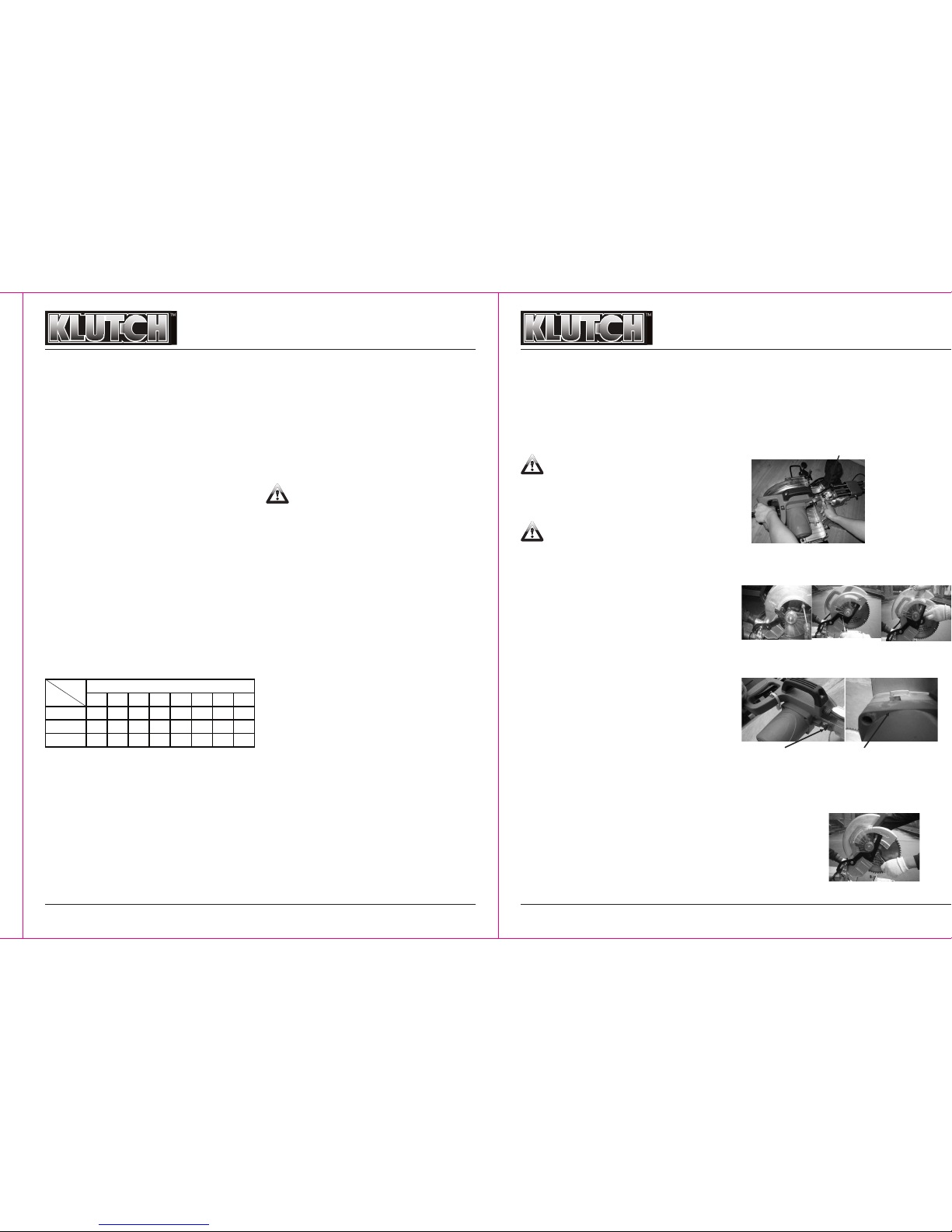
3. Lock the saw blade in its upward position. To do so, pull
out the Lock Pin Assembly (#55-58) and turn it clockwise
90°before securing it. (Figure A)
4. Loosen the Triangle Bolt (#78) that holds the Fasten Plate
(#77) in place (Figure B). Then remove the Bolt (#81) (Figure
C). Do not loosen the two Bolts (#80) (Figure D).
5. Depress the Rotor Clamp Assembly to keep the saw blade
from turning. (Figure E)
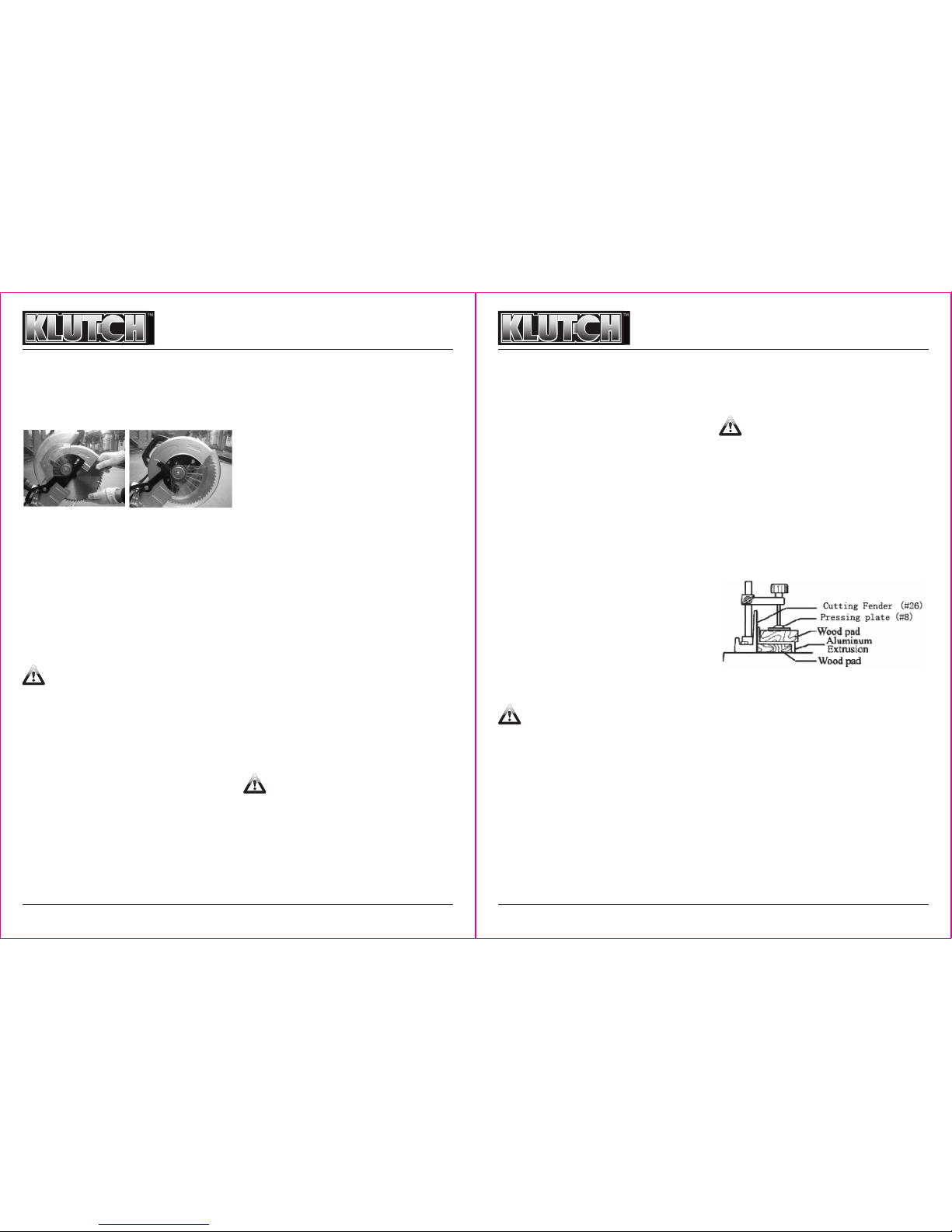
6. Using the Hex Sleeve Spanner (#161), remove the Arbor
Fasten Bolt (#74), the Arbor Flat Washer (#73) and Outer
Flange (#72) which are connected with the Arbor (#112)
NOTE: Remove the Arbor Fasten Bolt (#74) by turning it
CLOCKWISE. (Figure F)
Lock Pin Assembly (#55-58)
Figure A
Figure B Figure C Figure D
Rotor clamp assembly
(#137-139)
Rotor clamp assembly
up position
Figure F
25 50 75 100 125 150 175 200
0-10
18
guage 18
guage 16
guage 16
guage 14
guage 14
guage 12
guage 12
guage
10. 1-13
16
guage 16
guage 14
guage 14
guage 14
guage 12
guage 12
guage 12
guage
13. 1-15
14
guage 14
guage 12
guage 12
guage 12
guage 12
guage 12
guage - -
Total Extension Cord Length (in Feet)
AMP
RATING
Length

10in. LASER GUIDE COMPOUND
MITER SAW OWNER’S MANUAL
10in. LASER GUIDE COMPOUND
MITER SAW OWNER’S MANUAL
4 of 9
7. Release pressure on the rotor clamp assembly.
8. Wearing heavy-duty work gloves to avoid accidental cuts,
remove the old saw blade.
9. Install the new saw blade, making sure the arrow direction
on the Saw Blade matches the arrow on the Safe Guard
(#108). The teeth of the saw blade should be pointing
downward. (See Figure G)
10. Reassemble the Outer Flange (#72) onto the Arbor (#112)
and against the Saw Blade. Use the Hex Sleeve Spanner
(#161) to firmly tighten the Arbor fasten bolt (#74) onto the
Arbor (#112) by turning it COUNTERCLOCKWISE.
11. Swing the Fasten Plate (#77) back in place, making sure
the blade guard covers the saw blade (Figure H).
12. Make sure the Safety Guard (#108) returns to its original
position prior to operating the Miter Saw.
HOW TO USE THE PLASTIC SAFETY GUARD
1. The Plastic Safety Guard (part #63) automatically rotates to
cover the Saw Blade when the Saw Handle is lifted. When
the Handle is lowered, the Plastic Safety Guard rotates back
out of the way.
WARNING: Do not disconnect or remove the Plastic
Safety Guard (part #63). Do not operate the saw if the Plastic
Safety Guard is damaged or missing.
2. If the Plastic Safety Guard (part #63) becomes dirty and the
Saw Blade cannot be seen clearly, disconnect the power
cord and clean the Safety Guard with a soft, damp cloth. A
mild detergent may be used. Do not use solvents as they
can damage the Safety Cover.
HOW TO USE THE DUST BAG ASSEMBLY
1. The Dust Bag Assembly (part #162 not shown on the parts
drawing) helps keep the work area clean by catching
sawdust and wood chips thrown off by the Saw Blade.
2. When the Dust Bag Assembly (part #162) is half full, remove
it from the saw, and empty it by using the zippered opening
in the bottom of the bag.
3. For more efficient sawdust collection, the hose from a shop
vacuum (not provided) may be attached onto the top of the
Dust Bag Pipe (part #122).
HOW TO ADJUST THE CUTTING DEPTH
1. The cutting depth can be adjusted to accommodate Saw
Blades of a slightly smaller diameter and to assure that the
workpiece is cut completely.
2. Make sure the saw is unplugged before making this
adjustment.
3. Push the saw forward as far it will go. Check to see whether
the edge of the Saw Blade passes completely through the
Kerf Board (part #45).
4. If the Saw Blade does not pass completely through the Kerf
Board (part #45), lower the Saw Blade slightly by turning the
Butterfly Screw (part #117) located beside the Plastic Safety
Guard (part #63) COUNTERCLOCKWISE.
5. After adjusting the Butterfly Screw (part #117), press down
on the saw and make sure that the Saw Blade does not
contact the bottom of the guide plate (part #23) or any other
part of the Base (part #4).
6. If the Saw Blade touches, turn the Butterfly Screw (part
#117) CLOCKWISE to raise the Saw Blade slightly until it
clears.
7. The cutting depth of the saw can also be adjusted from the
sliding shaft(#70), and the butterfly screw(#7) can be
adjusted to the left side of elliptical holes.
HOW TO ADJUST THE MITER ANGLE
1. Raise the saw to the up position.
2. Grasp the Orientation Handle (#39) to move the worktable to
the desired angle.
HOW TO ADJUST THE BEVEL ANGLE
1. The Saw Blade can rotate up to 45 degrees to the left.
2. Lock the saw to avoid sliding by the Butterfly Screw (#82).
3. Loosen the Swivel Arm Lock Handle (#17) on the Gauge
Plate (part #19).
4. Rotate the saw to the desired angle, and tighten the Swivel
Arm Lock Handle (#17)
5. Unplug the saw from its electrical power source, and check
to make sure the Saw Blade does not contact any part of
workbench (part #23).
HOW TO SECURE THE WORKPIECE ONTO THE SAW
BASE
WARNING: You must secure the workpiece firmly to
the workbench (part #23) before cutting. A loose workpiece
may fly off or become jammed in the saw, potentially causing
serious personal injury or property damage.
1. Mount the Vise Jaw (part #7-12) on one side of the
workbench (part #23), and insert the post of the Vise
Assembly into the hole on either side of the Cutting Fender
(#26).
2. Insert a sample of the workpiece to determine its thickness,
and adjust the Vise Jaw (part #7-12) for the best fit.
3. Tighten the Vise Assembly in to position, using the Butterfly
Screw (part #11).
5 of 9
4. Check to make sure the vise assembly does not interfere
with the movement of the saw by moving the saw through its
range. Move or re-adjust the Vise Assembly if necessary.
5. Remove the sample workpiece, and place the actual
workpiece on the workbench (part #26) against the Cutting
Fender (#26).
6. Secure the workpiece in place by tightening the Adjusting
Handle (part #12) of the Vise Jaw.
NOTE: Make sure to use the Supporting Bracket (part #6)
when cutting a long piece of work.
HOW TO USE THE HOLDER ASSEMBLY
1. The two Supporting Brackets (part #6) can be installed by
inserting two rod ends in to the holes located in the sides of
the Base (part #4) and tightening the Butterfly Screw (part
#5).
2. The Cutting Fender (part #26) provides a support that is level
with the workbench (part #23).
3. When cutting very long workpieces you need to have
additional supports.
4. To cut multiple pieces of the same length, use the Plastic
Stopper (part #32). The Plastic Stopper (part #32) allows you
to measure only one time, but cut many times.
5. Slide the Plastic Stopper (part #32) onto one of the
Supporting Bracket (part #6).
6. With the saw unplugged, measure the distance from the
Saw Blade to the Plastic Stopper (part #32).
7. Slide the Plastic Stopper (part #32) to the desired distance
from the Saw Blade, and lock the Plastic Stopper (part #32)
in position with the Butterfly Screw (part #5).
NOTE: Make sure the Butterfly Screw (part #27), which
secures the Supporting Bracket (part #6) in place, is tight to
keep the Holder Assembly from moving.
How to Make a Basic Cut
WARNING: Before plugging in and turning on the
saw, make sure you have observed all safety warnings and
precautions.
1. To release the Lock Pin Assembly (part #55-58), push the
Handle down.
2. Before turning on the saw, make sure the Saw Blade does
not come in contact with any part of the workbench (part
#23).
3. Pull the saw back so that the Saw Blade will initially contact
the upper rear corner of the workpiece.
4. Squeeze the Switch Handle (part #101) to power the saw.
Allow the Saw Blade to reach its maximum speed before
starting the cut.
5. Lower the Saw Blade into the workpiece. Press down gently.
Do not force the saw. Allow the Saw Blade to do its work.
6.As the saw reaches the lower part of its swing, pull the saw
forward to continue cutting across the workpiece.
Continue pulling the saw forward until the cut is completed.
Do not stop midway in the cut.
7. When the cut is completed, release the Switch Handle (part
#101). Wait for the Saw Blade to stop turning before raising
the Handle to its upward position.
8. Remove the cut workpiece from the Saw.
CAUTION: The wood needs to be positioned under
the center of the Saw Blade. If you are cutting a small piece,
use a spacer block to move the wood to be cut so that your
cut is lined up with the center of the blade.
HOW TO USE A WOOD PAD
1. In some cases it can be useful to mount a wood pad against
the Cutting Fender (part #26) or under the workpiece.
2. A thin flat piece of wood can be mounted to the Cutting
Fender (part #26), using screws (not provided) and nuts (not
provided) on the backside of the Cutting Fender (part #26).
NOTE: Be sure to countersink the screw heads.
3. When cutting odd shaped pieces like aluminum extrusion,
the correct size wood pads can support the extrusion while
cutting.
HOW TO CUT GROOVES
1. The cutting depth of the saw can be adjusted, using the
Butterfly Screw (part #117).
2. Unplug the saw.
3. Loosen the Butterfly Screw (part #117), which is located on
the bracket (part #54).
4. Adjust the Butterfly Screw (part #117) until the desired
cutting depth is obtained. You may need to make
adjustments while measuring the distance from the lowered
Saw Blade to the workbench (part #23) until the desired
depth is reached.
5. Tighten the Butterfly Screw (part #117) firmly.
NOTE: Remember to readjust the Butterfly Screw (part #117)
before returning to standard cuts.
How to Adjust the Bevel Cut Guide
1. Push the saw all the way forward toward the Cutting Fender
(#26).
2. Lower the saw all the way down and lock it in place, using
the Lock Pin Assembly (part #55-58)
Figure G

10in. LASER GUIDE COMPOUND
MITER SAW OWNER’S MANUAL
10in. LASER GUIDE COMPOUND
MITER SAW OWNER’S MANUAL
Laser Beam Outlet
Figure I
6 of 9
3. Tighten the Butterfly Screw (part #82) at the side of the
Swivel Arm to prevent the saw from sliding.
4. Loosen the Swivel Arm Lock Handle (part #17) at the back of
the saw.
5. Turn the saw to your ideal position according to the angle
mark on the Gauge Plate (part #48).
6. Retighten the Swivel Arm Lock Handle (part #17) firmly.
HOW TO INSPECT AND REPLACE THE CARBON
BRUSHES
WARNING: Before accessing the Carbon Brushes
(#142), make sure the saw is unplugged
1. Two Carbon Brushes (#142) are located on both sides of the
Motor Housing (#140).
2. Periodically remove the Brush Caps (part #127) with a
screwdriver to inspect the Carbon Brushes (#142).
3. The Carbon Brushes (#142) have wear limit markings on
them. You must use the Block Brushes within the wear limit.
When they are worn to the limit they must be replaced. Do
not operate the saw if the brushes are worn beyond the limit.
4. The Carbon Brushes (#142) must be replaced in pairs. For
proper operation, the Brushes should wear equally.
5. If the Carbon Brushes are dirty, carefully scrape or wipe
them off.
6. When installing, make sure the Carbon Brushes fit closely
into their holders, and the Springs (#143) operate freely.
7. Make sure the carbon portion of the Carbon Brushes
contacts the Motor Armature, and the springs face away
from the motor.
8. After inspecting or replacing the Carbon Brushes, replace
the Brush Holder Caps (part #145) with a screwdriver, and
tighten firmly.
NOTE: The Carbon Brushes are made of carbon and have the
strength of pencil lead. Do not overstress the Carbon Brushes
(#142) while cleaning or they may break.
HOW TO USE LASER GUIDE
WARNING: Before plugging in and turning on the
saw, make sure you have observed all safety warnings and
precautions and that it is safe to begin cutting.
LASER RADIATION – NEVER STARE INTOTHE LASER
BEAM OUTLET. AVOID DIRECT EYE EXPOSURE WITH
THE LASER AT ALL TIMES!
Wavelength 650nm, 1mW Maximum Output, Class II
1. Secure the workpiece in place.
2. Turn on the Laser switch (#102).
3. Cut the workpiece as the Laser Beam shows.
4. If the Laser is not lined up with the Blade, please turn down
the saw head and check if the laser beam lines up with the
sawblade and the center of the cutting slot. Loose and
adjust the screw on the beam, if the beam shines on the
blade and you cannot see the beam on the other side, which
has been in alignment already(Figure I).
5. Always turn off the Laser when finished cutting.
6. No assembly needed for the laser product. Wipe the dust or
oil on the laser product after use.
ABOUT KERF BOARD
This saw is assembled with the Kerf Board (#45) in the turn
base. The Kerf Board has been adjusted at the factory so that
it does not contact the Saw Blade.
CLEANING, INSPECTION AND MAINTENANCE
CAUTION: Always disconnect the Compound Miter
Saw from its power supply before performing any cleaning,
inspection, or maintenance.
• Do not pour water into the Motor through the Motor Vents.
• Do not use solvents to wipe off the saw.
• With a brush or soft cloth, remove all the sawdust from the
saw.
• If necessary, wipe with a damp cloth. You may use a mild
detergent.
• Once clean, lubricate all of the moving parts with light oil.
• When storing, keep the Compound Miter Saw in a box, or
cover it with a cloth.
7 of 9
No Name Pcs No Name Pcs
1 Fasten Nut M12 1 83 Swivel Arm 1
2 D12 Flat Washer 1 84 Spacer 2
3 Inner hex bolt M12X12 1 85 straight line Bearing 4
4 Base 1 86 Bearing Cover 2
5 Butterfly screw M6X20 1 87 M4×8 Cross Head Bolt 4
6 Supporting Bracket 2 88 M4×10 Cross Head Bolt 2
7 Butterfly screw M6X20 2 89 Cord Clip 1
8 Pressing Plate 1 90 Connecting Tube 1
9Vise Jaw Post 1 91 Outer Hex BoltM5×16 4
10 Vise Jaw Base 1 92 Cross Head Self-tapping Bolt ST3.5×14C 6
11 Butterfly screw M6X20 1 93 Power Switch 1
12 Adjusting Handle 1 94 Connection Pole (Four holes )1
13 Cord 1 95 Handle Base 1
14 Cord Protector 1 96 M5×20 Cross Head Bolt 4
15 Fasten Nut M12 2 97 Cord Clip 1
16 D12 Flat Washer 2 98 Cord Protector 1
17 Swivel Arm Lock Handle 1 99 Cross Head Self-tapping Bolt ST3.5×14C 2
18 D10 Washer 1 100 Laser Transformer 1
19 Gauge Plate 1 101 Switch Handle 1
20 Inner Hex fasten bolt M8×10 2 102 Laser Switch 1
21 Inner Hex fasten bolt M8×20 2 103 Handle Cover 1
22 Outer Hex Bolt M12×75 1 104 Assistant Handle 1
23 Workbench 1 105 Cross Head Self-tapping Bolt ST4.8×22F 2
24 Inner Hex Bolt M8×25 4 106 Inner Flange 1
25 Arbor Flat Washer 4 107 Adjusting Ring 1
26 Cutting Support Plate 1 108 Safety Guard 1
27 Butterfly Screw M6×40 2 109 Ball Bearing 619/8 1
28 Spring 1 110 Pivot Clip Spring φ16 1
29
Φ
10 Steel Ball 1 111 Bevel Wheel 1
30 M5×10 Cross Head Bolt 1 112 Pivot 1
31 Workbench Index 1 113 Ball Bearing 6304 1
32 Plastic Stopper 1 114 Straight Key 4×4×12 1
33 Friction Slice 1 115 Bearing Baffle 1
34 Across Head Bolt with tray M4×8 2 116 M5×12 Across Head Bolt with tray 2
35 Arbor Flat Washer 1 117 Butterfly Screw M6×30 1
36 Hex Head Nut M10 1 118 Knurling Nut 1
37 Gauge Locking Shaft 1 119 M4×10 Across Head Bolt 1
38 2.5X14 Spring Round Pin 1 120 D4 Flat Washer 1
39 Gauge Orientation Handle 1 121 Cord Clip 1
40 Out hex head bolt M10×40 1 122 Dust Bag Pipe 1
41 Gauge Orientation Handle Cap 1 123 M5×16 Across Head Bolt 2
42 D5 Flat Washer 2 124 Plastic stopper 1
43 M5×16 Cross Head Bolt 2 125 Cross Head Self-tapping Bolt ST3.5×9C 2
44 Workbench Step 1 126 Swivel Arbor 1

10in. LASER GUIDE COMPOUND
MITER SAW OWNER’S MANUAL
10in. LASER GUIDE COMPOUND
MITER SAW OWNER’S MANUAL
8 of 9 9 of 9
No Name Pcs No Name Pcs
45 Kerf Board 1 127 Safety Guard Spring 1
46 M4×12 Cross Head Bolt 7 128 Big Gear 1
47 Outer Hex bolt M12×40 1 129 Cross Head Bolt M6 1
48 Gauge 1 130 Ball Bearing6201 1
49 Copper Rivet 2 131 Wind Shield Ring 1
50 Inner Hex Bolt M8×20 5 132 Rotor Assembly 1
51 D8 Spring Washer 1 133 Cross Head Self-tapping Bolt ST4.2×60C 2
52 M4×12 Cross Head Bolt 1 134 Stator Assembly 1
53 Swivel Arm Index 1 135 Ball Bearing 6200 1
54 Bracket 1 136 Bearing Base Rubber 1
55 Lock Pin 1 137 Stator Clamp Glove 1
56 Spring Round Pin D2.5×14 1 138 Stator Clamp Glove 1
57 Lock Pin Spring 1 139 Stator Clamp 1
58 Lock Pin Handle 1 140 Motor Housing 1
59 Pivot Pin 1 141 Across Head Bolt with tray M5×20 4
60 Inner Hex Bolt M5×16 1 142 Carbon Brush 2
61 Fasten Nut M6 1 143 Spring 2
62 D6 Washer 1 144 Brush Holder 2
63 Plastic Safety Guard 1 145 Brush Holder Cap 2
64 Plastic Safety Guard Spring 1 146 Pressing Plate 1
65 Plastic Safety Guard Gear 1 147 Pivot Pin 1
66 Bracket Rubber Ring 1 148 Spring D7 1
67 D5 Flat Washer 3 149 split cotter D2×10 1
68 D5 Flat Washer 1 150 Adjusting Screw 1
69 Fasten Nut M5 1 151 Spring Round Pin 4×28 1
70 Sliding Shaft 2 152 Adjusting Screw Base 1
71 Blade 1 153 Adjusting Nut 1
72 Outer Flange 1 154 Hex Nut M8 1
73 Arbor Flat Washer 1 155 Swivel Arm Lock Handle 1
74 Arbor Fasten Bolt 1 156 M4×10 Cross Head Bolt 2
75 Cord Protector 1 157 D4 Flat Washer 2
76 Small Rubber Ring 4 158 Laser 1
77 Fasten Plate 1 159 Laser Base 1
78 Triangle Bolt 1 160 M4×10 Cross Head Bolt 1
79 Gear Guard 1 161 Spanner (not shown on parts drawing) 1
80 M4×8 Cross Head Bolt 2 162 Dust Bag 1
81 M5×12 Cross Head Bolt 1 163 Carbon Brush 2
82 Butterfly ScrewM6×20 1

10in. LASER GUIDE COMPOUND
MITER SAW OWNER’S MANUAL
WARNING
Some dust created by power sanding, sawing, grinding, drilling, and other construction activities contains chemicals known to
the State of California to cause cancer, birth defects or other reproductive harm. Some examples of these chemicals are:
• Lead from lead-based paints,
• Crystalline silica from bricks and cement and other masonry products, and
• Arsenic and chromium from chemically treated lumber.
Your risk from these exposures varies, depending on how often you do this type of work. To reduce your exposure to these
chemicals: work in a well ventilated area, and work with approved safety equipment, such as those dust masks that are specially
designed to filter out microscopic particles.
Distributed by
Northern Tool + Equipment Co.,
2800 Southcross Drive West
P.O. Box 1499 Burnsville, MN 5337-0499
Made in China.
Other Klutch Saw manuals
Popular Saw manuals by other brands

E.H. Wachs
E.H. Wachs 08-051-MAN user manual

Mainca
Mainca BC-2800 Translation of the original instructions

Parkside
Parkside 364705 2101 Translation of the original instructions

Makita
Makita 5007NB parts list

Sealey
Sealey SM4 instructions

Clarke
Clarke Woodworker CMS10S2B Operation & maintenance instructions