1. Insta ation
1.1 Physica
The instrument is built in a plastic box to be installed in a distribution board panel. The instrument’s position must be fixed with locks.
Natural air circulation should be provided inside the distribution board cabinet, and in the instrument’s neighbourhood, especially underneath the instrument, no other
instrumentation that is source of heat should be installed.
1.2 Instrument Connection
1.2.1 Power Supp y
The instrument requires an AC or DC voltage power supply as specified in technical parameters. The supply inputs are separated from other circuits of the instrument.
It is necessary to connect an auxiliary supply voltage in the range as declared in technical specifications table to the terminals AV1 ( No. 9, L ) and AV2 ( No.10, N ). In case
of DC supply voltage the polarity of connection is generally free, but for maximum electromagnetic compatibility the grounded pole should be connected to the terminal AV2.
The supply voltage must be connected via a disconnecting device ( switch - see installation diagram ). It must be situated directly at the instrument and must be easily
accessible by the operator. The disconnecting device must be labelled as the disconnecting device of the equipment. A C-character double circuit breaker at the nominal
value of 1A may be used for the disconnecting device; however its function and position must be clearly marked (symbols „O" and „I" according to EN 61010 – 1). If one of the
supply signals is neutral wire N (or PEN) usually a single breaker in the line branch is sufficient. If a switch and fuse is used, the T1A (delayed) type is recommended.
1.2.2 Measured Vo tages
Connect measured voltages in wye ( star ), delta or Aron configuration to terminals VOLTAGE / N (No. 11), U1 (No. 12), U2 (No. 13), and U3 (No. 14). The N terminal stays
free at delta and Aron connections. Phase rotating direction is free.
It is advisable to protect the supply leads by 1A safety fuses (F1A type, for example).
The type of voltage and currents connection must be entered in Installation parameters : the code shows the amount of connected phases, 3Y means three-phase connection
in wye ( star ), 3D in delta. 3A means Aron connection. For 1Y3 or 1D3 setup, the instrument operates in, so called, single phase mode – see full-scale Operating Manual.
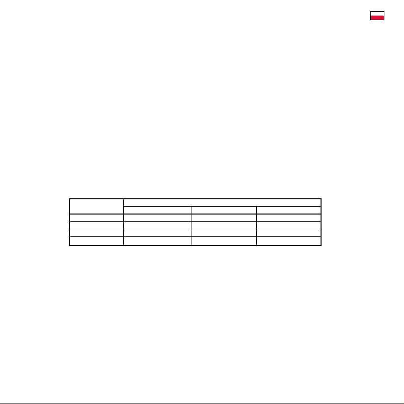
Connection of Measured Voltages – VOLTAGE Group of Terminals
Terminal Type of connection
VOLTAGE wye-star (3Y) delta (3D) Aron (3A)
U1L1-phase voltage L1-phase voltage L1-phase voltage
U2L2-phase voltage L2-phase voltage L2-phase voltage
U3L3-phase voltage L3-phase voltage L3-phase voltage
UNneutral wire voltage - -
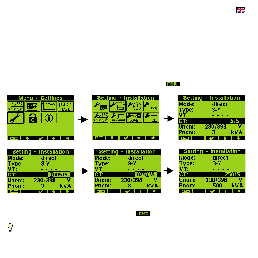
In the case of indirect connection via the measuring voltage transformers, it is necessary to enter this matter ( connection Mode ) and the values of the VT ratios during the
setup of the instrument.
The maximum cross section of the conductors to the terminal panels is 2.5 mm2.
1.2.3 Measured Currents
The instruments are designed for indirect current measurement via external CTs only. Proper current signal polarity (S1 & S2 terminals) must be observed. You can check the
polarity by the sign of phase active powers on the instrument display (in case of energy transfer direction is known, of course).
The CT-ratio must be set. in the Installation group of parameters (see below).
The I2 terminals stay free in case of the Aron (A) connection.
To get better precision when using overweighted CTs, you can apply more windings of measured wire through the transformer Then you must set the multiplier
parameter (see below) For standard connection with 1 winding, the multiplier must be set to 1
The current signals from 5A or 1A (or 0.1A for the „X/100mA“ models) instrument current transformers must be connected to the CURRENT connector terminal pairs I11 –
I12, I21 – I22, I31 – I32 (No. 1 ÷ 6).