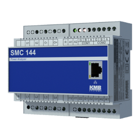
KMB SMC 133 User manual

KMB systems, s. r. o.
Dr. M. Hor´akov´e 559, 460 06 Liberec 7, Czech Republic
E-mail: kmb@kmb.cz, Web: www.kmb.cz
Operating Manual for
SMC 133
Firmware 4.0
Revision 2.0 / 30.3.2021
The most actual version of this manual is available online at http://www.KMB.cz/
Contents
1 General Description 1
2 Operating the Meter 2
2.1 Safety requirements when using SMC 133 . . . . . . . . . . . . . . . . . . . . . . . . . . . . . . . 2
2.2 Usedsymbols............................................... 2
2.3 Installation of the instrument . . . . . . . . . . . . . . . . . . . . . . . . . . . . . . . . . . . . . . 4
2.3.1 Supplyvoltage .......................................... 4
2.3.2 Measuredvoltage......................................... 5
2.3.3 Measuredcurrents ........................................ 5
2.3.4 Communication peripherals . . . . . . . . . . . . . . . . . . . . . . . . . . . . . . . . . . . 5
2.3.5 Inputsandoutputs........................................ 7
2.4 DownloadingdatatoPC......................................... 7
2.5 Energymeterreadings.......................................... 8
3 Technical Specifications 9
3.1 BasicParameters............................................. 9
3.2 MeasuredQuantities........................................... 11
3.3 InputsandOutputs ........................................... 14
4 Maintenance, Service, Warranty 15

Remote Communication Interface
N = RS-485
E = Ethernet, RS-485
Current Inputs
X/5A = 5A AC a 1A AC (standard indirect measurement)
X/1OOmA = 1OO mA AC (indirect measurement with 1OO mA CT)
SMC 133 U 23O X/5A E
Instrument Model
Auxiliary Power Supply
SMC 133 = Power analyser and datalogger, 3U, 3I
SMC 133D = Power analyser and datalogger, 3U, 3I, LCD
U = 85 V ÷ 510 VAC, 85 V ÷ 35O VDC, 2 universal DIO
S = 1O V ÷ 26 VAC, 1O V ÷ 36 VDC, internal UPS
L = 2O V ÷ 5O VAC, 2O V ÷ 75 VDC, internal UPS
Nominal Measuring Voltage
23O = 23O V/4OO V
1OO = 57,7 V/1OO V
Figure 1: Schematics of the SMC 133 ordering options and variants. It includes special codes for proper current
and voltage rating options.
1 General Description
The SMC 133 is specially designed for monitoring of energy and power quality in advanced power systems and
smart grids. It is intended to be used mostly for DIN rail mounting. This display-less design with multiple
communication options is suitable for a wide spectrum of automation tasks in modern buildings, distributed
power generation, remote supervision of the infrastructure and also remote load management. Two different
user interfaces are offered - SMC 133 D with a small embedded color display on the front panel for simple local
value reading and an unobtrusive SMC 133 without display with limited ability for for hostile user interaction.
To protect the actual setup and collected data each instrument can be locked by a custom pin. It uses standard
RS-485 serial line for communication with remote control systems. Optionally it can be equipped with other
communication peripherals such as Ethernet, USB, WiFi, ZigBee (custom options).
It is equipped with three voltage input and three current inputs. The default current input option X/5A
uses common X/5A or X/1A current transformers. The instrument can be supplied with inputs customized for
current transformers with X/100 mA ratio,
Warning! The X/100mA, options are specially designed to be used only in combination with provided
external current sensors which are supported with the respective option.
The SMC 133 is available in several configurations according to the customer requirements1. See the ordering
scheme on figure 1.
1Complete and most up to date list of optional and other accessories are available on request from the device vendor.
1

SMC 133
Power Analyzer
S2 S1 S2 S1 S2 S1
I1 I2 I3
NL1 L2 L3
VOLTAGE INPUTS
DIGITAL I/O COM
X1 X2
GC B- A+
D1 C2 D2
RUN
ALM
AUX PWR
C1
U
ETH
SMC 133
Power Analyzer
RUN CHG ALM G B- A+
COM
X1 X2
PWR STATUS
NL1 L2 L3 S2 S1 S2 S1 S2 S1
I1 I2 I3
VOLTAGE INPUTS
ETH
Figure 2: The instrument SMC 133 with auxiliary power supply option ”U“ (left) and ”S“ or ”L“ (right).
2 Operating the Meter
2.1 Safety requirements when using SMC 133
Warning !: When working with the instrument it is necessary to perform all necessary measures for the protection
of persons and property against injury and electric shock.
•The device must be operated by a person with all required qualifications for such work and this person
must know in detail the operation principles of the equipment listed in this description!
•When the device is being connected to the parts which are under dangerous voltage it is necessary to comply
with all the necessary measures to protect users and equipment against injury with electrical shock.
•Person, performing the installation or maintenance of the instrument must be equipped with and must use
personal protective clothing and tools.
•If the analyzer is used in a manner not specified by the manufacturer, the protection provided by the
analyzer may be impaired.
•If the analyzer or its accessories appear to be impaired or not functioning properly, do not use it and send
it in for repair.
2.2 Used symbols
Alternating current (AC);
To indicate on the rating plate that the equipment is suitable for alternating
current only; to identify relevant terminals.
2

Direct current (DC);
To indicate on the rating plate that the equipment is suitable for direct current
only; to identify relevant terminals.
Both direct and alternating current;
To indicate on the rating plate that the equipment is suitable for both direct and
alternating current (universal); to identify relevant terminals.
Protective earth; protective ground;
To identify any terminal which is intended for connection to an external conductor
for protection against electric shock in case of a fault, or the terminal of a
protective earth (ground) electrode.
Functional earthing;
functional grounding (US) To identify a functional earthing (grounding) terminal,
for example, of a specially designed earthing (grounding) system to avoid causing
malfunction of the equipment.
Earth; ground;
To identify an earth (ground) terminal in cases where neither the symbol 5018 nor
5019 is explicitly required.
Class II equipment;
To identify equipment meeting the safety requirements specified for Class II
equipment according to IEC 61140.
Caution;
To indicate that caution is necessary when operating the device or control close to
where the symbol is placed, or to indicate that the current situation needs operator
awareness or operator action in order to avoid undesirable consequences.
Operator’s manual; operating instructions;
To identify the location where the operator’s manual is stored or to identify
information that relates to the operating instructions. To indicate that the
operating instructions should be considered when operating the device or control
close to where the symbol is placed.
Computer network;
To identify the computer network itself or to indicate the connecting terminals of
the computer network
3

CE marking;
declaration that the product meets the requirements of applicable EC directives.
USB interface
To identify the connecting terminal of the USB port.
Crossed-out wheelie-bin;
products in scope of the EU WEEE Directive are labelled with a crossed-out bin
symbol as required by this directive. The symbol indicates that end users should
segregate the product from other waste at end-of- life.
2.3 Installation of the instrument
Natural air circulation should be provided inside the distribution board cabinet, and in the instrument’s neigh-
borhood. Especially underneath the instrument, no other instrumentation that is source of heat should be
installed or the instrument might overheat and/or the internal temperature value measured may be influenced.
A connection wire’s maximum cross section area is 2.5mm2in case of all screw terminals.
The SMC 133 is primarily intended for DIN-rail mounting. Dimensions of the instrument are on figure 3.
There are also positions marked with dash dot lines of holes for wall-mounting with three screws.
60.6
90
21.5 10
45
62
58106
99.8
30.3
SMC 133
Power Analyzer
001 03 2014
SMC 133 L
Figure 3: Dimensions of the SMC 133 analyzer.
2.3.1 Supply voltage
The power supply terminal is labeled as X1 and X2. The two terminals are complemented with a symbol (U,
L or S), indicating the respective auxiliary voltage option (details in ch. 3). Proper supply voltage must be
connected to the terminals X1 and X2 via a circuit breaking device (power switch – see installation diagram on
4

figure 4). It has to be located left to the instrument and easily reachable by the operator. The circuit breaking
device must be identified as the equipment power disconnection switch. A circuit breaker of the nominal value
1Ais a convenient circuit breaking device. Its function and position has to be clearly identified (symbols ‘0’
and ‘I’ acc. to IEC EN 61010-1). Internal power supply is galvanically isolated from internal circuits.
2.3.2 Measured voltage
The measured voltages are connected to the terminals L1, L2 and L3. Connect the neutral wire to the terminal
N. With delta or Aaron connections terminal N remains unused. Voltage measurement inputs are connected
with internal circuits over high impedance.
It is suitable to protect the measured voltage lines for example with 1A fuses of the required rating. Measured
voltages can also be connected via instrument voltage transformers. A connection cable maximum cross section
area is 2.5mm2for voltage terminals.
2.3.3 Measured currents
The instruments are designed for indirect current measurement via external CT only. Proper current signal
polarity (S1 or S2 terminals, k or l in the older notation) must be observed. You can check the polarity by the
sign of phase active powers on the instrument display, its web pages or in the ENVIS.Daq application.
X/5A current input option The current signals from 5A or 1A instrument current transformers must be con-
nected to the terminal pairs I11, I12, I21, I22, I31, I32 with a cable of maximum cross section area 2.5mm2and
a maximum length of 3 m.
X/100mA current input option The supplied current transformers (which are standard accessory) must be
clamped on measured wires with proper isolation and interconnected with corresponding terminal pairs I11,
I12, I21, I22, I31, I32 using a twisted-pair cable of maximum length of 3 m. The secondary winding of the
transformers is led to the screw terminals. The S1, S2 (or ”K“/”L“ and ”k“/”l“) orientation is marked on the CT
guide groove. A connection cable maximum cross section area is 1.5mm2.
Warning !: Connection of the common X/5A, X/1A or another unsupported current transformers to an
instrument with X/100mA option is strictly forbidden !!! The instrument can be seriously damaged!
2.3.4 Communication peripherals
All peripherals stated below are galvanically isolated from the rest of the instrument and from each other.
Ethernet interface (optional) 100 Mbit Ethernet interface with RJ-45 connector (100Base-TX) labeled as ETH
is situated on a top panel of the device. Ethernet interface can be used as substitution for the primary RS-485
for connection of the device to LAN and for easy connection of remote control PC.
RS-485 serial line serves usually as a remote communication for reading of actual data, archive downloading
and device configuration. Serial RS-485 line uses terminals A+, B- with shielding at terminal Gof COM1 block
(fig. 6). The end point of the communication line must be properly terminated with ˜120Ωresistor.
5

Option S:
10 ÷ 36VDC
Option L:
20 ÷ 75VDC
MV/LV
Transformer L1
L2
L3
N
PE
Option U:
85 ÷ 510VAC
85 ÷ 350VDC
SMC 133
Power Analyzer
RUN CHG ALM G B- A+
COM
X1 X2
PWR STATUS
NL1 L2 L3 S2 S1 S2 S1 S2 S1
I1 I2 I3
VOLTAGE INPUTS
ETH
UU
USB
Option U:
85 ÷ 510VAC
85 ÷ 350VDC
L1
L2
L3
X/100mA
X/5A
S2 S1
S2 S1
S2 S1
X/100mA
X/5A
S2 S1
S2 S1
S2 S1
X/100mA
X/5A
S2 S1
S2 S1
S2 S1
Figure 4: An example of typical installation of SMC 133 instrument — options L or S for various LVDC power
supplies and option U for universal LVAC. Typical connection options for voltage measurements: star, delta and
single phase feeders. Option E (left) for Ethernet port remote communication, option U (right) for local USB
communication port (all instruments provide RS485 serial line).
Option S:
10 ÷ 26VAC
9 ÷ 36VDC
Option L:
20 ÷ 50VAC
20 ÷ 75VDC
SMC 133
Power Analyzer
RUN CHG ALM G B- A+
COM
X1 X2
PWR STATUS
NL1 L2 L3 S2 S1 S2 S1 S2 S1
I1 I2 I3
VOLTAGE INPUTS
ETH
MV/LV
Transformer
L1
L2
L3
X/100mA
X/5A L1
L2
L3
N
PE
S2 S1
S2 S1
S2 S1
MV/LV
Transformer
L1
L2
L3
X/100mA
X/5A L1
L2
L3
N
PE
S2 S1
SMC 133
Power Analyzer
S2 S1 S2 S1 S2 S1
I1 I2 I3
NL1 L2 L3
VOLTAGE INPUTS
DIGITAL I/O COM
X1 X2
GC B- A+
D1 C2 D2
RUN
ALM
AUX PWR
C1
U
S2 S1
S2 S1
Figure 5: Example of typical connection of SMC 133 with indirect measurement via voltage transformers.
6

Figure 6: Typical wiring of the RS-485 communication line terminals in SMC 133 .
USB (optional) communication port for USB slave is located on the front panel. This communication port is
intended for easy local configuration and fast download of archived data to the local PC. Use the supplied USB
cable only (USB-A/mini). SMC 133 is a USB 2.0 slave device. For correct operation it needs a driver installed
in your operating system (see the ENVIS user guide for more info).
2.3.5 Inputs and outputs
Instrument provides two separate universal I/O ports with terminals C1, D1 and C2, D2. Each DI/O port can
be used individually as an input or an output function. For a correct operation of the I/O it is necessary to use
an external power supply with nominal voltage 12 to 24 VDC. Appropriate polarity of supply voltage for input
resp. output function must be kept.
Warning! Digital I/Os are unipolar. Right polarity must be kept for a proper operation of the terminal.
Incorrectly connected external power supply can damage the instrument.
DI/O as a digital input DI is connected to the selected I/O terminal (D1 or D2) and a common terminal (C1
or C2) with external power supply in the following way: the current flows from positive terminal of the supply
through the external input contact to a DI terminal (D1 or D2) and than from the common terminal (C1 or C2)
back to the negative terminal of the external power supply.
DI/O as a digital output DO is connected to the selected I/O terminal (D1 or D2) and a common terminal (C1
or C2) with external power supply in the following way: the current flows from positive terminal of the supply to
the C1 or C2 terminal and from a DI terminal (D1 or D2) through the controlled load to the negative terminal
of the supply. If an I/O port is used as an output (its behavior is controlled by an internal logic function) the
instrument also indicates its activation with the respective input register.
2.4 Downloading data to PC
Connect the instrument to the PC and run ENVIS.Daq application. Select the appropriate communication
option and connect to the instrument. In the next screen press Refresh All. This will load and display the actual
7

II
OUT IN
SMC 133
DIGITAL I/O COM
X1 X2
GC B- A+
D1 C2 D2
RUN
ALM
AUX PWR
C1
24V
U
Figure 7: An example of mixed input and output of SMC 133 supplied by a 12 VDC power supply PWR.
status of each supported archive.
Device Information section contains editable description and name under which the actual record is stored.
Time Frame for Other Archives tab allows you to limit the date ranges of all archives by the time interval of the
main archive. In the Destination section the actual storage can be selected - either to the SQL database or to
the file. The check boxes in Archives to Download determines which specific archive(s) you want to download.
The actual download will start by pressing the Download All button. When finished the archive can be
viewed in the ENVIS application. User can open the downloaded file directly from ENVIS.Daq.
2.5 Energy meter readings
SMC 133 has an embedded three phase, four-quadrant energy meter with automatic meter reading functions and
multiple programmable tariffs (Time-of-Use, TOU). The instrument registers active energy (EP, EP+, EP-) and
reactive energy (EQL, EQC or EQC+, EQC-, EQL+, EQL-). According to the configuration of meter readings
are shuffled to the respective tariffs. It automatically provides summaries per phase. For star connections and
single phase measurements it can also register energy for each phase separately.
Meter data readings can be downloaded and analyzed in ENVIS or via the standard ModBus protool in any
other system.
8

3 Technical Specifications
3.1 Basic Parameters
Auxiliary Voltage
model „S“ model „L“ model „U“
rated auxiliary volta e ran e
AC auxiliary volta e ran e, f: 40 ÷ 100 Hz N/A
DC auxiliary volta e ran e
power supply 3,5 W 7 VA / 3W
overvolta e cate ory III (50 V) II (100 V) III (300 V) / II (600 V)
internal backup power supply adjustable 1 ÷ 3600 s N/A
pollution de ree 2
maximum operatin altitude 2000 m
connection isolated, polarity free
spec-AUX-en
12 ÷ 30 VDC 24 ÷ 60 VDC 100 ÷ 420 VAC
96 ÷ 250 VDC
85 ÷ 510 VAC
10.8 ÷ 36 VDC 20 ÷ 75 VDC 85 ÷ 350 VDC
9

Other Specifications
operational temperature (variant S, L) -20 ÷ 60°C
operational temperature (variant U) -25 ÷ 70°C
stora e temperature -40 ÷ 80°C
operational and stora e humidity < 95 % - non-condensable environment
EMC – immunity
EMC – emissions
communication ports
communication protocols
display (SMC 133D only) color TFT LCD, 160x128 pixels, 1.8”
samplin frequency 50 Hz (60 Hz) 25,6 kHz (23,04 kHz)
accuracy of RTC
capacity of RTC backup battery > 5 years (without supply volta e applied)
power supply backup battery Li-ion 18350 (char in deactivated under 0°C)
protection class II
wei ht max. 0.25 k
spec-Other-en
EN 61000 – 4 - 2 (6 kV / 8 kV)
EN 61000 – 4 - 3 (10 V/m up to 3 GHz)
EN 61000 – 4 - 4 (4 kV)
EN 61000 – 4 - 5 (2 kVLL / 4 kVLG)
EN 61000 – 4 - 6 (10 V)
EN 61000 - 4 - 8 (100 A / 1000 A)
EN 61000 – 4 - 11 (250 periods)
EN 55011, class A
EN 55022, class A (not for home use )
RS-485 (2400 ÷ 921600 Bd), optional USB, Ethernet 100Base-T
KMB, Ethernet to RS-485 ateway (optional module),
Modbus RTU and TCP, Modbus Master (optional module),
WEB server, JSON,
DHCP, SNTP
± 2 seconds per day
in ress protection
front panel
whole instrument
IP 40
IP 20
dimensions
front panel
whole instrument
106 x 45 mm
106 x 90 x 58 mm
10

3.2 Measured Quantities
Measured Quantities – Voltage
50 / 60 Hz
measurin ran e 40 ÷ 70 Hz
uncertainty ± 10 mHz
Voltage
volta e input option standard variant („230“)
measurin ran e line-to-neutral
measurin ran e line-to-line
temperature drift
300V CAT IV
permanent overload
peak overload, 1 second
burden power (impedance) < 0.03 VA (Ri = 7.84 MΩ)
Voltrage Unbalance
measurin ran e 0 ÷ 10 %
measurin uncertainty ± 0.3% of rd or ± 0.3
THDU
measurin ran e 0 ÷ 20 %
measurin uncertainty ± 0.5
reference conditions
measurin ran e
measurin uncertainty twice the levels of class II acc. to IEC 61000–4-7 ed. 2
spec-U-en
Frequency
fNOM– nominal frequency
UNOM (UDIN)– rated volta e 180 ÷ 280 VAC
4 ÷ 420 VAC
7 ÷ 720 VAC
intrinsic uncertainty (tA=23±2ºC) +/- 0.05 % of rd ± +/- 0.05 % of rn
+/- 0.03 % of rd ± +/- 0.01 % of rn / 10 ºC
measurement cate ory
1252 VAC (UL–N)
2800 VAC (UL–N)
Harmonics up to 50th order (40th order @ 60 Hz)
other harmonics up to 200 % of class 3 acc. to IEC 61000–2-4 ed. 2
10 ÷ 100 % of class 3 acc. to IEC 61000–2-4 ed. 2
11

Measured Quantities – Current, Temperature
Current
current input option „X 100mA“ „X 5A“
measurin ran e
temperature drift
150V CAT IV 150V CAT IV
permanent overload
burden power ( impedance)
Current Unbalance
measurin ran e 0 ÷ 100 %
measurin uncertainty ± 1 % of rd or ± 0.5
reference conditions
measurin ran e
measurin uncertainty
THDI
measurin ran e 0 ÷ 200 %
measurin uncertainty THDI <= 100 %: ± 0.6
THDI > 100 %: ± 0.6 % of rd
Temperature (internal sensor, measured value affected by the instrument power dissipation)
measurin ran e - 40 ÷ 80°C
measurin uncertainty ± 2ºC
spec-IT-en
INOM (IB) – rated (basic) current 0.1 AAC 5 AAC
0.00025 ÷ 0.15 AAC 0.0125 ÷ 7.5 AAC
intrinsic uncertainty (tA=23 ±2 ºC) +/- 0.05 % of rd ± +/- 0.05 % of rn
+/- 0.03 % of rd ± +/- 0.01 % of rn / 10 ºC
measurement cate ory
1 AAC 10 AAC
peak overload
1 second, maximum repetition
frequency > 5 minutes
10 AAC 90 AAC
< 0.001 VA (Ri < 0.1 Ω) < 0.001 VA (Ri < 0.1 Ω)
Harmonics & Interharmonics up to 50th order (40th order @ 60 Hz)
other harmonics up to 1000 % of class 3 acc. to IEC 61000–2-4 ed.2
500 % of class 3 acc. to IEC 61000–2-4 ed.2
Ih <= 10 % INOM: ± 1 % INOM
Ih > 10 % INOM: ± 1 % of rd
12

Measured Quantities – Power, Power Factor, Energy
act. / react. power uncertainty
temperature drift of powers
Energy
measurin ran e
active ener y uncertainty class 1 acc. to EN 62053 – 21
reactive ener y uncertainty class 2 acc. to EN 62053 – 23
spec-PQEE-en
Active Reactive Power, Power Factor (PF), cos φ (PNOM = UNOM x INOM)
reference conditions “A”:
ambient temperature (tA)
U, I
for active power, PF, cos φ
for reactive power
23 ± 2 ºC
U = 80 ÷ 120 % UNOM, I = 1 ÷ 120 % INOM
PF = 1.00
PF = 0.00
± 0.5 % of rd ± 0.005 % PNOM
PF & cos φ uncertainty ± 0.005
reference conditions ”B”:
ambient temperature (tA)
U, I
for active power, PF, cos φ
for reactive power
23 ± 2 ºC
U = 80 ÷ 120 % UNOM, I = 2 ÷ 120 % INOM
PF >= 0.5
PF <= 0.87
± 1 % of rd ± 0.01 % PNOM
PF & cos φ uncertainty ± 0.005
± 0.05 % od rd ± 0.02 % PNOM / 10 ºC
corresponds to U & I measurin ran es
4 quadrant ener y counters for both active and reactive ener ies
13

3.3 Inputs and Outputs
Digital Outputs & Digital Inputs: universal 1+1 DIO (only models with „U“ auxiliary voltage)
Digital Outputs
type Opto-transistor, unipolar (Cx +, Dx -)
load ratin
Digital Inputs
type Opticaly isolated, unipolar (Cx -, Dx +)
maximum volta e
volta e for “lo ical 1“
volta e for “lo ical 0“
input current
spec-IO-en
35 VDC, 30 mADC
dynamic parameters (pulse output):
- pulse duration
- ap duration
- maximum frequency
S0 - compatible
50 ms
>= 50 ms
10 Hz
30 VDC
> 7 VDC
< 3 VDC
5 mA @ 12V / 13 mA @ 24V
dynamic par. (pulse counter):
- pulse/ ap duration
- maximum frequency
>= 0.5 / 0.5 ms
1 kHz
14

4 Maintenance, Service, Warranty
Maintenance: the SMC 133 power analyzer does not require any additional maintenance during its operation
besides the regular maintenance processes for the whole cabinet. For reliable operation it is only necessary to
meet the operating conditions specified and not expose the instrument to violent handling and contact with
water or chemicals which could cause mechanical damage.
The lithium cell built in the instrument can backup a real time circuit for more than 5 years without power
supply, at average temperature 20°Cand load current in the instrument less than 10 µA. If the cell is empty, it
is necessary to ship the instrument to the manufacturer for battery replacement.
The 18350 rechargeable Li-ion battery cell for the instrument operation backup is also optionally installed
inside the SMC 133 option S or L. If the battery malfunctions it is necessary to ship the instrument to the
manufacturer for battery replacement.
Service: in the case of failure or a breakdown of the product, you should contact the supplier at their address:
K M B Systems, s. r. o.
Tˇr. dr. M. Hor´akov´e 559
460 05 Liberec 7
Czech Republic
Tel. 485 130 314
E-mail: km[email protected]
Web: www.kmb.cz
The product must be in proper packaging to prevent damage during transit. A description of the problem
or its symptoms must be delivered together with the product.
If a warranty repair is claimed, the warranty certificate must be sent in. In case of an out-of-warranty repair
you have to enclose an order for the repair.
Warranty certificate: warranty period of 24 months from the date of purchase is provided for the instrument,
however, no longer than 30 months from the day of dispatch from the manufacturer. Problems in the warranty
period, provably because of faulty workmanship, design or inconvenient material, will be repaired free of charge
by the manufacturer or an authorized servicing organization.
The warranty ceases even within the warranty period if the user makes unauthorized modifications or changes
to the instrument, connects it to out-of-range quantities, if the instrument is damaged due to ineligible or
improper handling by the user, or when it is operated in contradiction with the technical specifications presented.
Type of product: SMC 133 . . . . . . . . . . . . . . . . . Serial number: . . . . . . . . . . . . . . . . . . . . . . . . . . .
Date of dispatch: . . . . . . . . . . . . . . . . . . . . . . . . . . . Final quality
inspection:
...........................
Manufacturer’s seal: . . . . . . . . . . . . . . . . . . . . . . . . . . .
Date of purchase: . . . . . . . . . . . . . . . . . . . . . . . . . . . Supplier’s seal: . . . . . . . . . . . . . . . . . . . . . . . . . . .
15
Table of contents
Other KMB Measuring Instrument manuals
Popular Measuring Instrument manuals by other brands

HERON
HERON H.0IL Operating and maintenance instructions

DV Power
DV Power RMO200 manual

Sonic Driver
Sonic Driver FIXED-UFM operating instructions

Shinko
Shinko JC-33A instruction manual

Applied Precision
Applied Precision Working Standard WS 2120 quick guide

First Stop Safety
First Stop Safety MemoryPAT-Blu User notes