Sensor Model Inom [A] d [mm] Description
CA-JRF MOI 333M-80 100 100 A 80 mm Flexible current sensor, max. 100A, diameter 80mm, 3 in IP65 bayonet locking connector
CA-JRF MOI 333M-80 300 300 A 80 mm Flexible current sensor, max. 300A, diameter 80mm, 3 in IP65 bayonet locking connector
CA-JRF MOI 333M-115 100 100 A 115 mm Flexible current sensor, max. 100A, diameter 115mm, 3 in IP65 bayonet locking connector
CA-JRF MOI 333M-115 300 300 A 115 mm Flexible current sensor, max. 300A, diameter 115mm, 3 in IP65 bayonet locking connector
CA-JRF MOI 333M-115 1000 1000 A 115 mm Flexible current sensor, max. 1000A, diameter 115mm, 3 in IP65 bayonet locking connector
CA-JRF MOI 333M-115 2500 2500 A 115 mm Flexible current sensor, max. 2500A, diameter 115mm, 3 in IP65 bayonet locking connector
Sensors with Inom above 2500A on request.
Table 1: Current sensor options
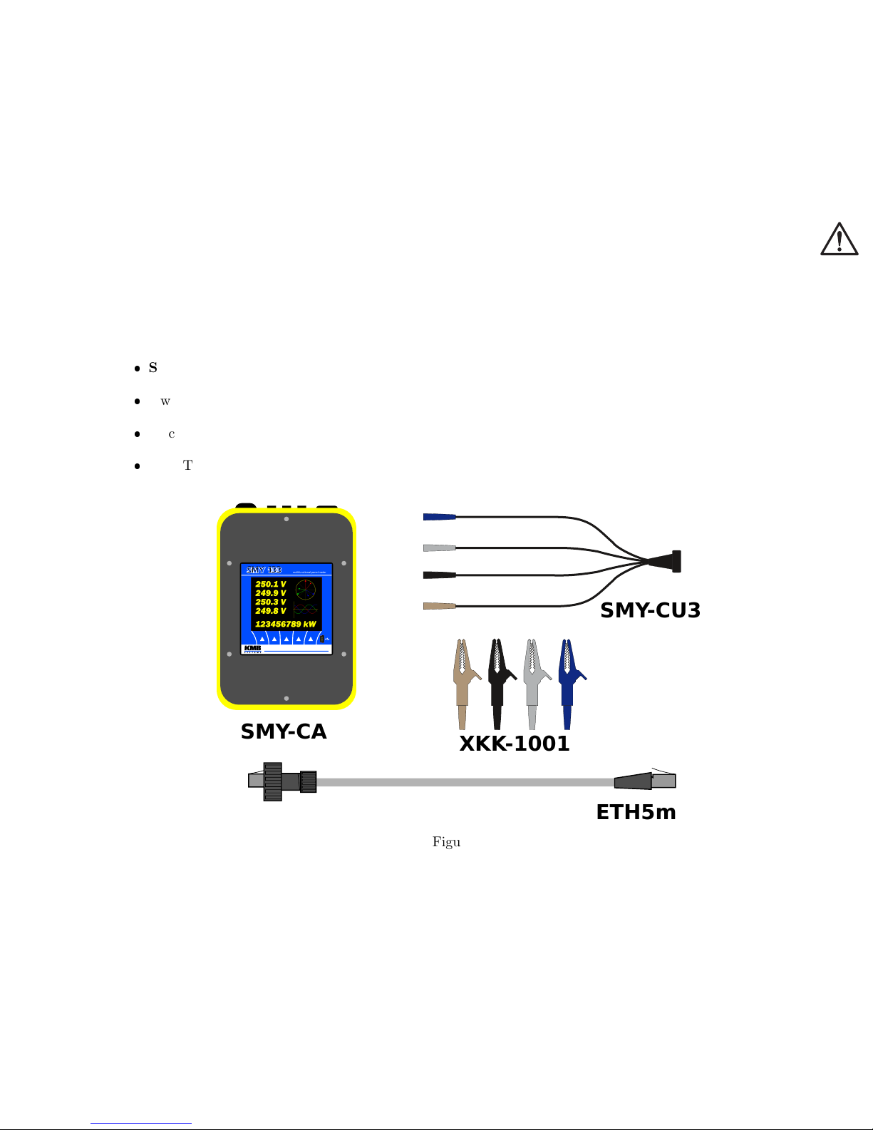
2 Operating the Meter
2.1 Safety requirements when using SMY-CA
Warning !: When working with the instrument it is necessary to perform all necessary measures for the
protection of persons and property against injury and electric shock.
The device must be operated by a person with all required qualifications for such work and this person
must know in detail the operation principles of the equipment listed in this description!
When the device is being connected to the parts which are under dangerous voltage it is necessary to comply
with all the necessary measures to protect users and equipment against injury with electrical shock.
Person, performing the installation or maintenance of the instrument must be equipped with and must use
personal protective clothing and tools.
If the analyzer is used in a manner not specified by the manufacturer, the protection provided by the
analyzer may be impaired.
If the analyzer or its accessories appear to be impaired or not functioning properly, do not use it and send
it in for repair.
2.2 Instrument overload warning
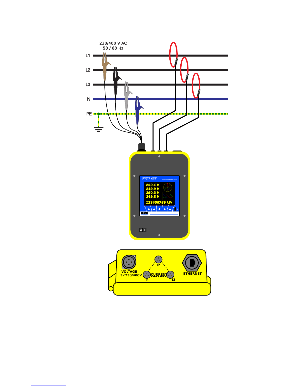
When connecting to the measured voltage using croco clips it is necessary to pay more attention to correct
connection of conductor N (neutral, blue).
Warning !: An incorrect connection of the conductor N to one of phase voltages causes built-in power
supply overload and serious damage of the instrument!!!
It is always strongly recommended to connect first the conductor N (blue) to the network neutral conductor.
Then check this connection properly and only then connect other wires to the voltages of phases L1, L2, L3.
2.3 Installation
The instrument can be used only in networks with maximum voltages not-exceeding its maximum available
power supply voltage (see technical specifications). For its operation, the instrument requires supply voltage
which is provided directly from measured voltage of phase L1. If current measurement is required too, use
appropriate current sensors with 333mV output.
2