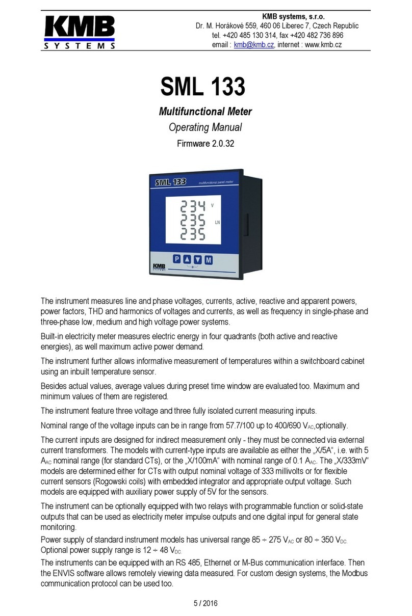
KMB SMV User manual

KMB systems, s.r.o.
Dr. M. Horákové 559, 460 06 Liberec 7, Czech Republic
tel. 420 485 130 314, fax 420 482 736 896
email : [email protected], internet : www.kmb.cz
SMV, SMP
SMVQ, SMPQ
Multifunctional Panel Meters &
Power Quality Analyzers
Operating Manual
Firmware v. 1.0.0.3035
07 / 2013

SMV / SMP / SMVQ / SMPQ
LIST O CONTENTS
1. GENERAL...........................................................................5
1.1 Common features....................................................................................................................................... 5
2. BRIE DESCRIPTION........................................................7
2.1 Instrument Connection.............................................................................................................................. 7
2.2 SMV / SMVQ Instrument Setup................................................................................................................. 8
2.2.1 Locking and Unlocking of the Instrument..............................................................................................9
2.3 SMV / SMVQ Instrument Operation.........................................................................................................10
2.4 SMP / SMPQ Instrument Setup............................................................................................................... 13
2.4.1 The Instrument Lock........................................................................................................................... 14
2.4.1.1 Locking........................................................................................................................................ 14
2.4.1.2 Unlocking from the User Locked State........................................................................................ 14
2.4.1.3 Unlocking from the Admin Locked State......................................................................................14
2.5 SMP / SMPQ Instrument Operation.........................................................................................................14
3. DETAILED DESCRIPTION...............................................16
3.1 Basic Characteristics............................................................................................................................... 16
3.2 Manufactured Models and Marking........................................................................................................ 18
3.3 Installation................................................................................................................................................ 21
3.3.1 Physical.............................................................................................................................................. 21
3.3.2 Protective Conductor Connection....................................................................................................... 21
3.3.3 Supply Voltage Connection................................................................................................................. 21
3.3.4 Measured Electrical Quantities Connection........................................................................................21
3.3.4.1 Measured Voltages...................................................................................................................... 21
3.3.4.2 Measured Currents...................................................................................................................... 22
3.3.4.2.1 Standard „X/5A”-Option Instruments – Current Signals Connection.....................................22
3.3.4.2.2 „F“-Option Instruments – Current Signals Connection........................................................22
3.3.4.2.3 „S“- and „P“- Option Instruments – Current Signals Connection.........................................23
3.3.5 Connection Setting.............................................................................................................................. 24
3.3.5.1 Connection Mode, Type and VT/CT Ratios.................................................................................24
3.3.5.2 Nominal Voltage UNOM and Nominal Power PNOM..................................................................24
3.4 Instrument Manual Manipulation and Setting........................................................................................ 25
3.4.1 SMV/SMVQ Instrument Manipulation and Setting...............................................................................25
3.4.2 SMP/SMPQ Instrument Manipulation and Setting...............................................................................25
3.4.2.1 Data Area – Status Bar - Toolbar................................................................................................25
3.4.2.2 Main Menu................................................................................................................................... 26
3.4.2.3 Actual Data Group....................................................................................................................... 26
3.4.2.4 Daily and Weekly Graphs............................................................................................................ 27
3.4.2.5 Electricity Meter Data Group........................................................................................................ 28
3.4.2.6 Power Quality Data Group........................................................................................................... 28
3.4.2.7 Instrument Setting....................................................................................................................... 28
3.4.2.7.1 Display Setting..................................................................................................................... 28
2

SMV / SMP / SMVQ / SMPQ
3.4.2.7.2 Installation Setting................................................................................................................ 28
3.4.2.7.3 Clock Setting........................................................................................................................ 28
3.4.2.7.4 Average Values Processing Setting....................................................................................29
3.4.2.7.5 I/O Setting........................................................................................................................... 29
3.4.2.7.6 Remote Communication Setting........................................................................................... 29
3.4.2.7.7 Embedded Electricity Meter Setting....................................................................................30
3.4.2.7.8 Archiving Setting................................................................................................................. 30
3.4.2.7.9 Power Quality Evaluation Setting........................................................................................30
3.4.2.8 Instrument Lock........................................................................................................................... 31
3.4.2.9 Instrument Information................................................................................................................. 31
3.4.2.9.1 Info – General Window........................................................................................................ 31
3.4.2.9.2 Info – Archive Status........................................................................................................... 31
3.4.2.9.3 Info – Producer.................................................................................................................... 32
3.5 Description of Operation......................................................................................................................... 32
3.5.1 Method of Measurement..................................................................................................................... 32
3.5.1.1 Voltage Fundamental Frequency Measurement Method.............................................................32
3.5.1.2 Voltage and Current Measurement Method.................................................................................32
3.5.1.3 Power and Power Factor Evaluation Method...............................................................................33
3.5.1.4 Fundamental Harmonic Power, Power Factor and Unbalance Evaluation Method......................34
3.5.1.5 Voltage Events Evaluation Method.............................................................................................. 35
3.5.1.6 Harmonics, Interharmonics and THD Evaluation Method............................................................36
3.5.1.7 Flicker Evaluation Method........................................................................................................... 36
3.5.1.8 Ripple Control Signal (RCS) Evaluation Method.........................................................................36
3.5.2 Measured Values Evaluation and Aggregation...................................................................................36
3.5.2.1 Display Actual Values Evaluation and Aggregation.....................................................................36
3.5.2.2 Average Values Evaluation.......................................................................................................... 37
3.5.2.2.1 Maximum and Minimum Average Values............................................................................38
3.5.2.3 Recorded Values Aggregation..................................................................................................... 41
3.5.3 Harmonics, Interharmonics and THD.................................................................................................. 41
3.5.3.1 Harmonics, Interharmonics and THD Aggregation......................................................................41
3.5.3.2 Harmonics and THD Presentation............................................................................................... 42
3.5.4 Embedded Electricity Meter................................................................................................................ 42
3.5.4.1 Electric Energy Processing.......................................................................................................... 42
3.5.4.2 Maximum Active Power Demand Registration.............................................................................42
3.5.4.3 Setting......................................................................................................................................... 43
3.5.4.4 SMV/SMVQ Instrument Energy Presentation..............................................................................43
3.5.4.5 SMV /SMVQ Instrument Maximum Active Power Demand Presentation.....................................44
3.5.4.6 SMP/SMPQ Instrument Energy Presentation..............................................................................44
3.5.4.7 SMP/SMPQ Instruments Maximum Active Power Demand Presentation....................................45
3.5.5 Power Quality..................................................................................................................................... 45
3.5.5.1 Power Quality Evaluation............................................................................................................. 45
3.5.5.2 Power Quality Presentation......................................................................................................... 46
3.5.6 Record Blocking.................................................................................................................................. 46
3.6 Inputs & Outputs..................................................................................................................................... 47
3.6.1 Inputs & Outputs Connection.............................................................................................................. 48
3.6.1.1 Relay Output Connection............................................................................................................. 48
3.6.1.2 Impulse Output Connection......................................................................................................... 48
3.6.1.3 Digital Input Connection............................................................................................................... 48
3.6.1.4 Analog Input Connection............................................................................................................. 48
3.6.2 Inputs & Outputs Setup....................................................................................................................... 49
3.6.2.1 Digital Output Setup – Standard Output......................................................................................49
3.6.2.1.1 Input Events........................................................................................................................ 49
3.6.2.1.2 Control Quantity Size Event................................................................................................50
3.6.2.1.3 Instrument State Event........................................................................................................ 52
3.6.2.1.4 Permanent State Event.......................................................................................................52
3.6.2.1.5 Output Control Formula....................................................................................................... 53
3.6.2.1.6 Output Type........................................................................................................................ 53
3

SMV / SMP / SMVQ / SMPQ
3.6.2.2 Digital Output Setup - Impulse Output......................................................................................... 53
3.6.2.3 Digital Output Setup – Remote Controlled Output.......................................................................54
3.6.2.4 Digital Input Setup....................................................................................................................... 54
3.6.2.5 Analog Input (A) Setup................................................................................................................ 54
3.6.2.6 Temperature Input (T) Setup.......................................................................................................54
3.7 Additional irmware Modules................................................................................................................ 54
3.7.1 VE Module - Voltage Events............................................................................................................... 54
3.7.1.1 Voltage Events Evaluation........................................................................................................... 55
3.7.1.2 Voltage Events Presentation....................................................................................................... 55
3.7.2 RCS Module – Ripple Control Signal.................................................................................................. 56
3.7.2.1 RCS Evaluation........................................................................................................................... 56
3.7.2.2 RCS Processing Setting.............................................................................................................. 56
3.7.2.3 RCS Signal and RCS Telegram Visualization.............................................................................57
3.7.2.4 RCS Telegram Reception Indication with the A1/A2 LEDs..........................................................58
3.7.2.5 RCS Signal and Telegram Viewing in the ENVIS Program..........................................................58
3.7.3 GO Module – General Oscillograms...................................................................................................59
3.8 Transient Recording............................................................................................................................... 59
3.8.1 PQ RMS Trends and PQ Oscillograms...............................................................................................60
3.8.2 General Oscillograms......................................................................................................................... 60
3.8.3 RMS Trend and Oscillogram Triggering..............................................................................................61
3.8.3.1 General Triggering....................................................................................................................... 61
3.8.3.2 Wave Change Triggering............................................................................................................. 61
3.8.3.3 General Oscillogram Record Triggering Methods........................................................................61
4. COMPUTER CONTROLLED OPERATION......................63
4.1 Communication Links.............................................................................................................................. 63
4.1.1 Local Communication Link.................................................................................................................. 63
4.1.2 Remote Communication Link.............................................................................................................. 63
4.1.2.1 RS-232 Interface......................................................................................................................... 63
4.1.2.2 RS-485 Interface......................................................................................................................... 63
4.1.2.2.1 Communication Cable......................................................................................................... 64
4.1.2.2.2 Terminating Resistors......................................................................................................... 64
4.1.2.3 Ethernet (IEEE802.3) Interface....................................................................................................64
4.1.2.4 Communication Protocols............................................................................................................ 64
4.1.2.4.1 KMB Communications Protocol........................................................................................... 64
4.1.2.4.2 Modbus-RTU Communications Protocol.............................................................................64
4.2 The ENVIS Program................................................................................................................................. 64
4.3 Embedded Webserver.............................................................................................................................. 66
5. EXAMPLES O CONNECTIONS.....................................67
6. TECHNICAL SPECI ICATIONS.......................................73
7. MAINTENANCE, SERVICE..............................................81
4

SMV / SMP / SMVQ / SMPQ
1. General
This manual comprises description of SMV, SMP, SMVQ and SMPQ multifunctional panel meters and
power quality analyzers. All the instrument models share the same measuring & evaluating engine a
their characteristics are as follows :
•SMV – basic model with LED display
•SMP – same parameters and options as SMV, but with high resolution LCD display and
enhanced display capabilities, including day/week graphs, waveforms, phasors,harmonic
charts, status informations etc.
•SMPQ – the enhanced model with improved precision of current, power and energy
measurement, inter-harmonics and flicker severity indexes, voltage events and weekly
evaluation of power quality (EN 50160)
1.1 Common features
Standard Measurement Principles
•evaluation of electrical parameters in energy distribution systems in compliance with IEC
61000-4-30 ed. 2 class S
•four voltage inputs ( U1, U2, U3, UN )
•three ( I1, I2, I3 ; “33”-models ) or four ( I1, I2, I3, IN ; “44”-models ) current inputs
•measuring of electric quantities in three phase (from three- to five-wire) networks of nominal
voltage up to 400V AC (or up to 130 V AC for ”100”-models) directly, or via voltage
transformers
•current signal connection :
•standard „X/5A“ option models … 5A and 1A nominal current inputs
•„F“ option models … B3000/1000-line flexible Rogowski current sensors inputs
•„S“ option models … JC-line miniature split core current transformers input
•„P“ option models … JP-line miniature through-hole current transformers input
•sampling rate 128 / 96 samples/period, 10 / 12 periods continuous measurement cycle ( ~200
ms at 50 / 60 Hz ), gap-less
•selection of aggregation intervals from 200 ms/1 second up to 24 hours
•data flagging concept that eliminates double evaluation of critical events
•fixed window / floating window / thermal average values
•harmonic components up to 63rd according to IEC 61000-4-7 ed.2
•interharmonic components ( SMVQ/SMPQ only )
•digital flicker meter according IEC 61000-4-15
5

SMV / SMP / SMVQ / SMPQ
Electricity Meter
•four-quadrant three tariff electricity meter
•single phase and three phase energies
•maximum of average active power values ( power demand ) of current / last month and total
•automated electricity meter readings at preselected time intervals
Advanced Datalogging Capabilities
•high memory capacity for recording of aggregated measurement values
•maximum and minimum average values including timestamps
•day profiles (detailed day long record) at preselected date and at the day with maximum
demand
•optional voltage events evaluation and record ( firmware module VE; standard at the
SMVQ/SMPQ ), ripple control signal measurement ( RCS module ) and voltage event
oscillogram record ( GO module )
ully Configurable Inputs and Outputs for Control
•two configurable alarm LEDs on the front side panel
•two optional configurable relays or pulse outputs
•optional single digital input for time synchronization, tariff selection or for status monitoring
•optional universal analog input ( passive current loop 20 mA ) or the Pt100 temperature
sensor input
Communication Options / Data Acquisition
•built-in USB 2.0 communication port for fast data acquisition, configuration and firmware
upgrades
•proprietary protocol with free data acquisition software ENVIS
•optional remote communication interface ( RS 232 / RS 485 / Ethernet )
•MODBUS RTU and MODBUS TCP for simple integration with third party SCADA software
•embedded webserver ( for instruments with Ethernet interface )
•optional accessories :
•RS232/RS485 and USB/RS485 interface converters
•external GPS real time receiver for time synchronization via remote comm. Interface
6

SMV / SMP / SMVQ / SMPQ
2. Brief Description
This chapter provides a brief description of connection and basic operation of the instruments in a
typical installation. A detailed instrument description of all its features and connection possibilities
follows.
2.1 Instrument Connection
The instruments of the SMV / SMP / SMVQ / SMPQ series belong to equipment class I, therefore it is
absolutely necessary to connect the PE protective conductor to the PE terminal of the
instrument ! The recommended cross section of the protective conductor is 2,5 ÷ 4,0 mm2, loop with
diameter of 4,3 mm ( M4 terminal ).
It is necessary to connect an auxiliary supply voltage in the range as declared in technical
specifications table to the terminals AV1 ( L ) and AV2 ( N ). In case of DC supply voltage the polarity
of connection is generally free, but for maximum electromagnetic compatibility the grounded pole
should be connected to the terminal AV2.
The supply voltage must be connected via a disconnecting device ( switch - see installation diagram ).
It must be situated directly at the instrument and must be easily accessible by the operator. The
disconnecting device must be labelled as the disconnecting device of the equipment. A circuit breaker
at the nominal value of 1A may be used for the disconnecting device; however its function and
position must be clearly marked (symbols „O" and „I" according to EN 61010 - 1).
Fig. 2.1: T pical star (4Y) connection, mains 3 x 230/400 V
Measured phase-to-neutral voltages and neutral voltage (measured towards to the PE ) connect to
terminals VOLTAGE / N, U1, U2 and U3. Measured voltages must be protected, e.g. by 1A fuse.
Current signals from the current transformers at the nominal value of 5 or 1 A AC must be connected
to a pair of terminals CURRENT / I1k, I1l, I2k, I2l, I3k, I3l, or INk, INl. It is necessary to observe their
polarity (terminals k, l). Examples of other connections are mentioned below in the manual.
The maximum cross section of the conductors to the terminal panels is 2,5 mm2.
7

SMV / SMP / SMVQ / SMPQ
2.2 SMV / SMVQ Instrument Setup
When switching on the power supply, the instrument will perform a display test and then will display
the code „ Init", firmware release number and a group of measured values, e.g. phase voltages U1, U2,
U3 (or UN). The information is shown on the display as follows, for example:
In this case the LED- diode VLN indicates the type of displayed quantities, i.e. phase voltages. The
instantaneous measured values in phases L1, L2 and L3 can be viewed in the first three rows. In the
fourth row the value of voltage UN is displayed.
To display the real values of voltages, currents and other quantities, the instrument must be preset.
Setup of the instrument is stated by specifications, such as for example the type of measured voltage
[direct measuring or via metering voltage transformers (VT) and their conversions], the method of
voltage and current connection (star, delta, Aron ), or the conversion metering current transformers
(CT) etc. The summary of the basic parameters is stated in the table below.
Generally, besides nominal frequency ( fNOM , parameter P.03/3) it is only necessary to adjust the CT
conversion. Assuming that the conversion of used CT for inputs of current L1 to L3 is 750/5 A. To edit
the parameters, enter by pressing and holding the ► button (about 6 s). The display will show the
parameter P.00 (=lock). Another (short) touch of the ► button will switch to the group of parameters
P.01, with conversions of the current transformers. A flashing specification in the 2nd row designates
the actual selected parameter, which is the nominal secondary current of the CT. To keep the value of
5A, press ► and switch over to the next parameter in the third row. For example value 500 will start
flashing, which is the preset nominal primary current of the CT. This value can be gradually increased
by touches of the ▲button to 750 A.
Finally, to finish editing the parameters, press and hold the ► button again for about 6 sec. and the
instrument will get back to the display of measured values.
8
…..
SMV 44
VLL
VLN
A
W
var
VA
PF
cos
THD
har
m
En1
p
En3
p
Pav
Hz, i
USB
inIt
1780
k
M
k
M
inst.
av
max
.
min
time
SMV 44
VLL
VLN
A
W
var
VA
PF
cos
THD
har
m
En1
p
En3
p
Pav
Hz, i
USB
229
231
230
0.0
k
M
k
M
inst.
av
max
.
min
time
SMV 44
VLL
VLN
A
W
var
VA
PF
cos
THD
har
m
En1
p
En3
p
Pav
Hz, i
USB
0
P.00
k
M
k
M
inst.
av
max
.
min
time
►
lon
►
SMV 44
VLL
VLN
A
W
var
VA
PF
cos
THD
har
m
En1
p
En3
p
Pav
Hz, i
USB
5
P.01
500
500
k
M
k
M
inst.
av
max
.
min
time ►
SMV 44
VLL
VLN
A
W
var
VA
PF
cos
THD
har
m
En1
p
En3
p
Pav
Hz, i
USB
5
P.01
500
500
k
M
k
M
inst.
av
max
.
min
time
▲
SMV 44
VLL
VLN
A
W
var
VA
PF
cos
THD
har
m
En1
p
En3
p
Pav
Hz, i
USB
5
P.01
600
500
k
M
k
M
inst.
av
max
.
min
time ▲
SMV 44
VLL
VLN
A
W
var
VA
PF
cos
THD
har
m
En1
p
En3
p
Pav
Hz, i
USB
5
P.01
750
500
k
M
k
M
inst.
av
max
.
min
time
SMV 44
VLL
VLN
A
W
var
VA
PF
cos
THD
har
m
En1
p
En3
p
Pav
Hz, i
USB
230
229
228
0.0
k
M
k
M
inst.
av
max
.
min
time
►
lon

SMV / SMP / SMVQ / SMPQ
Other basic parameters can be edited in a similar way. Apart from these basic parameters (see
Tab.2.1) the instrument also includes a row of other parameters – their description is stated in
following chapters.
Tab.2.1: SMV - Summar of the basic parameters
Par. Row Description Range of adjustment Default
setting
P.00 2 lock 0(unlocked) / 1(locked) 0
P.01
2 nom . value of secondary CT 1 A / 5 A 5
3 nom . val. primary CT for I1 ÷ I31 ÷ 9900 A 5
4 nom . val. primary CT for IN1 ÷ 9900 A 5
P.02
2method of voltage connection – directly
or via VT - - - / 100 - - -
3 nom. val. of primary VT for U1 ÷ U30.1 ÷ 400 kV - - -
4 nom. val. of primary VT for UN0.1 ÷ 400 kV - - -
P.03 2 type of connection of U and I 3- Y / 3- D / 4-Y 3-Y
3 nominal frequency fNOM 50 / 60 Hz 50
P.04
2 display refresh cycle (in mains cycles ) 20 ÷ 200 mains cycles 30
3 resolution of displayed values 3 / 4 significant figures 4
4 display brightness 0 ÷ 3 3
P.05
2 U / I averaging method FIxed / FLoating / THermal FL
3 U / I averaging period 1 sec ÷ 60 mins 1 min
4 U / I average autoclear period NO / 1Day / 7Days / 1Month / 1Year NO
P.06
2 P / Q / S averaging method FIxed / FLoating / THermal FL
3 P / Q / S averaging period 1 sec ÷ 60 mins 15 mins
4 P / Q/ S average autoclear period NO / 1Day / 7Days / 1Month / 1Year NO
P.07 2 PavgE (el. meter group) aver. method Fixed / Floating FL
3 PavgE (el. meter group) averaging period 1 min ÷ 60 mins 15 mins
P.08
2 time zone shift -12 ÷ 13 hours 1
3 daylight saving NO / YES YES
4 time synchronization NO / mains Freq. / Comm.link / PPM NO
2 local time – DD.MM
P.09 3 local time – YYYY
4 local time – HH.MM
P.20
*)
2 remote communication rate 4.8 ÷ 215 kBd 9,6
3 remote communication address 1 ÷ 252 1
4 remote communication protocol 0 / 1-n / 1-O / 1-E / TS 0
P.20
)
2 remote comm. – IP address xxx.xxx.xxx.xxx 10.0.0.1
3 remote comm. - subnet mask xxx.xxx.xxx.xxx 255.255.
255.0
4 remote comm. - default gateway xxx.xxx.xxx.xxx 10.0.0.138
P.21
)
2 remote comm. - KMB-port 0 ÷ 65535 2101
3 remote comm. - web-port 0 ÷ 65535 80
4 remote comm. - Modbus-port 0 ÷ 65535 502
*)... for instruments with RS232 / RS485 remote comm. interface only
)... for instruments with Ethernet remote comm. interface only
2.2.1 Locking and Unlocking of the Instrument
The instruments are supplied in an „unlocked" state (parameter P.00 = 0), that means the basic
parameters can be randomly edited, following the procedure mentioned above. After putting it into
operation, the parameters editing can be „locked" and the instrument can be protected from possible
9

SMV / SMP / SMVQ / SMPQ
unqualified manipulation, by simply switching the parameter P.00 to the position 1(=locked).
Unlocking the instrument requires this particular procedure: following the above - mentioned method,
switch the instrument into the parameters display and by pressing the ▲ and ▼buttons find the
parameter P.00 – value 1 in the second row indicates the locked instrument. At the same time press
the ▲and ▼buttons - randomly selected number will appear in the third row. If it is odd, press ▲ and
if even, press ▼. Repeat this procedure until the parameter value in the 2nd row switches to the value
0, i.e. the „unlock" status. After that, any parameter can be found and adjusted.
2.3 SMV / SMVQ Instrument Operation
After activation of supply voltage, the instrument accomplishes internal diagnostics, updating of
internal database of measured data and then it starts to measure and display the instantaneous
measured values ( inst. ).
The row of LED-diodes on the left side indicate the type of displayed quantities - their summary is
stated in the chart below. The LED diodes k and M determine a multiplier (k=kilo, M=mega, kM=giga)
separately for specifications in rows 1÷3 and extra for row 4 (e.g. when displaying voltage, the diode k
indicates, that the specifications are in kV etc.).
Particular measured quantities can be changed over by using the ▲and ▼buttons. The buttons
►and ◄ can switch the type of displayed quantity: instant (inst.), average (avg.), maximum of
average (max.) or minimum of average (min.), except the quantities THD,harm and EN – these only
show instantaneous values.
Values avg. are evaluated with method and the time window according to parameters P.05 ( for U/I-
group ), P.06 ( for P/Q/S-group ), and P.07 (for PavgE of electricity meter group). Values max./min. are
maximum/mimimum values of the avg.-values reached since last clearing. You can check date & time
of last clearing of each group by listing to window time, which is indicated as Clrt in the 4th row. To
clear max./min. registered values of appropriate group manually, while in the appropriate Clrt -time
window press the ►and ◄ simultaneously and the date/time value starts flashing. Then confirm
clearing with the button ▼( pressing of different button will not clear anything ). Depending on the
listed average values group, only either U/I-group or P/Q/S-group average max/mins or PavgmaxE of
electricity meter group are cleared. If the instrument is locked, clearing is not possible.
In addition, the buttons ►and ◄ can display conditions of the
internal time circuit ( local time ) and immediate conditions of digital
inputs/outputs and so-called error code ( I/O,Err ).
At the I/O,Err.-window actual status of a digital input ( 1st row ) and
two digital outputs (2nd and 3rd row) are displayed. Active state
(closed) is indicated as “1”, inactive (open) as “0”.
At the 4th row the instrument error code is displayed. The E-00 code
means no errors. Other codes can indicate some instrument's
hardware problem – in such case contact the service organization.
The last two LEDs are alarm LEDs A1 and A2. Their function is programmable in the same way as
digital outputs.
Other comments on measured quantities:
•VLL, VLN, A : line voltage, phase voltage and phase current real effective values (TRMS). When the
measurement input is overloaded, the whole specification flashes.
•W, Var, VA : supply of active power or leading reactive power indicated as negative.
•P : actual power factor (or total - T.P.F., λ lambda).
•cos : power factor of the fundamental component. Displayed in four quadrants. Capacitance
character of the power factor indicated by the letter „c"; furthermore, supply of active power
indicated as negative.
10
SMV 44
VLL
VLN
A
W
var
VA
PF
cos
THD
harm
En1p
En3p
Pav E
Hz, i
USB
O1-0
I-0
02-1
E 00
k
M
k
M
inst.
av .
max.
.
min
time
min.
time
minI/O, Err.
A1
A2

SMV / SMP / SMVQ / SMPQ
•THD, harm : harmonic distortion (THD) and sizes of individual harmonic components of phase
voltages and currents. The evaluation is executed internally up to the 50th order, but the harmonics
up to 40th order only are displayed. The data is in percentage, except current harmonic data directly
in amperes. The order will display for 1sec after the selection by ►and ◄.
•En1p : Single-phase electrical energy. It is evaluated in four quadrants, i.e. separately - consumption
and supply of active energy and inductive and capacitive component of reactive energy. The data
are summary for all the tariff zones. The reset date & time are stated in the last window.
•En3p : Three - phase electrical energy. Again, it is evaluated in four quadrants, and in addition in
three preset tariff zones including a summary for all the zones ( setup of the tariff zones can be
implemented only by using connection with PC and control program ENVIS). Data displayed to 12
places across rows 1 ÷ 3. The last window again shows the reset date & time ( this specification is
equivalent to corresponding specification of En1p ). The energy counter reset ( common to En1p
and En3p ) is executed when „time" is displayed, by simultaneously pressing ►and ◄ and the
confirmation button ▼- pressing different buttons will not reset the counters. If the instrument is
locked, resetting is not possible.
•PavgE : active power demands ( = average active powers ) of “electricity meter group” (evaluated
independently of standard average values) , single-phase and three-phase values. The
instantaneous value (inst.) evaluated as the average with preset method and over preset period
( parameters P.07 ). The maximum achieved values of these power demands can be displayed in
the window „max." and occurrence date & time of the three-phase power demand in the third window
„max" „time". The last window shows the date & time of resetting the maximim value PavgmaxE
( window „time" with a Clrt indication in the 4th row ). The PavgmaxE can be reset manually in the way
already described above.
•Hz, a.i. : the mains frequency ( 2nd row ) is evaluated, if the voltage is present at least on one phase.
If the voltage is not connected or the frequency is out of measurable range, the diode flashes.
In the 4th row, analog input value is displayed. Either 20mA curent loop input value (recalculated to
preset range) or Pt100 temperature sensor input in °C.
Resolution of values displayed can be set to 3 or 4 significant figures ( parameter P.04 / 3 ). In case of
4 negative polarity is indicated by a flashing decimal point of the data.
11

SMV / SMP / SMVQ / SMPQ
Fig. 2.2: SMV – Measured Data Navigation Chart
12
U12
U23
U31
u2
U1
U2
U3
UN
I1
I2
I3
IN
P1
P2
P3
3P
Q1
Q2
Q3
3Q
S1
S2
S3
3S
PF1
PF2
PF3
3PF
cos1
cos2
cos3
3cos
● VLL
● VLN
● A
● W
● var
● VA
● PF
● cos
THDU1
THDU2
THDU3
THDUN
THDI1
THDI2
THDI3
THDIN
hU1-1
hU2-1
hU3-1
hUN-1
hI1-1
hI2-1
hI3-1
hIN-1
En1 - I
En2 - I
En3 - I
I
3En - I
I – t1
Pav 1
Pav 2
Pav 3
3Pav
Fr
analo
● En1p
● Hz, a.i.
● VLN
● THD
● A
● THD
● VLN
● harm
▼ ▲
▼ ▲
▼ ▲
▼ ▲
▼ ▲
▼ ▲
▼ ▲
▼ ▲
▼ ▲
▼ ▲
▼ ▲
▼ ▲
▼ ▲
▼ ▲
▼ ▲
hU1-50
hU2-50
hU3-50
hUN-50
◄ ►
hI1-50
hI2-50
hI3-50
hIN-50
◄ ►
● A
● harm
● En3p
● Pav E
line-to-line voltages [V]
voltage unbalance [%]
phase voltages [V]
phase currents [A]
active phase powers [W]
active 3-phase power [W]
reactive phase powers [var]
reactive 3-phase power [var]
apparent phase powers [VA]
apparent 3-phase power [VA]
phase F [-]
3-phase F [-]
▼ ▲
frequency [Hz]
analog input / temp. [°C]
THD of phase voltages [%]
THD of phase currents [%]
◄ ►
harmonic
components of
phase currents [A]
order 1÷ 50
3En - I
I – t2
3En - I
I – t3
3En - I
I–sum
day
year
HH.MM
Clrt
En1 - E
En2 - E
En3 - E
E
En1 - L
En2 - L
En3 - L
L
En1- C
En2- C
En3- C
C
◄►
◄► ◄►
◄►
◄► ◄► ◄►
◄ ►
day
year
HH.MM
Clrt
◄► ◄►
Pav m1
Pav m2
Pav m3
3Pav m
day
year
HH.MM
◄ ►
1-phase energy [Wh, varh]
3-phase energy [Wh, varh]
phase active power demands [W]
3-phase active power demand [W]
1-phase energy in 4
quadrants: active -
import (I) and export (E),
reactive – import (L) and
export (C)
3-phase energy (data
across 3 rows)
4 quadrants (I,E,L,C),
each in tariff 1÷3 and sum
(S)
single-phase and 3-phase active power demands –
instantaneous (continuous) and maximum attained ;
in third window, occurrence date & time of maximum
3-phase active power demand ;
resetting date & time in the last window (Clrt)
resetting time
and date in
the last
window (Clrt)
phase cos [-]
3-phase cos [-]
harmonic
components of
phase voltages [%]
order 1÷ 50

SMV / SMP / SMVQ / SMPQ
2.4 SMP / SMPQ Instrument Setup
When switching on the power supply, the instrument will display manufacturer's logo for approx. 0.5
sec and after that usually a group of actual measured values, e.g. phase voltages U1, U2, U3 (or UN), is
displayed. The information is shown on the display as follows, for example:
Quantities' names, i.e. U1, U2 and U3 indicates that actual phase voltages in phases L1, L2 and L3 are
displayed.
To display the real values of voltages, currents and other quantities, the instrument must be preset.
Setup of the instrument is stated by specifications, such as for example type of measured voltage
[direct measuring or via metering voltage transformers (VT) and their ratios], method of voltage and
current connection (star, delta, Aron ), or metering current transformers's (CT) ratios etc.
Besides nominal frequency ( fNOM ), usually it is only necessary to adjust the CT conversion. Assuming
that the conversion of used CT for inputs of current L1 to L3 is 750/5 A. To edit the parameters, press
the MENU button, navigate to the Menu-Setting with the buttons ►and ◄ and then choose it with
the button. In the Setting window choose Setting-Installation option. The Setting-Installation
window appears :
In the window navigate down to the current transformer ratio parameter of inputs I1÷ I3 ( CT ) and
choose with the button.
Now you can type new value of the parameter : with the ►button you can move from a digit to
another one and to set each digit to target value using the ▲and ▼buttons. At the end press the
button and the parameter is set. You can set nominal frequency fNOM and other parameters in the
same way.
Finally, when escaping the window you must confirm new setting by pressing the button and all of
the parameters of the window are stored into the instrument's memory.
The instrument includes a row of other parameters – their description is stated in following chapters.
13

SMV / SMP / SMVQ / SMPQ
2.4.1 The Instrument Lock
Three levels of locking to allow protection against unauthorized access are implemented. The active
protection level is symbolized in the main menu by three different states of the Lock icon :
●Unlocked – anyone with physical access to the instrument can freely set-up and
configure all parameters in the instrument, clear archives and other persistent data
or reset counters. In this state anyone can also lock the instrument.
●User Locked – fixed user password (PIN) is required if the instrument
configuration is changed or there is a request to clear any of the data.
●Admin Locked – user defined admin password (PIN) is required if the instrument
configuration is changed or there is a request to clear any of the data.
2.4.1.1 Locking
If the instrument is unlocked, you can lock it to either user or admin mode.
To lock the instrument into the user locked mode, simply switch in the Menu-Lock window the lock
from to . Then escape from the window with the button and confirm saving of changed state.
To lock the instrument into the admin locked state, press the buttons and ▼ simultaneously in the
Menu -> Lock window. Then normally hidden admin password option
appears. Choose it and type the new admin password code – the value
must be different from 0000. Then escape from the Menu-Lock window
with the button and confirm saving of changed state. The admin
locked state is indicated with the “A”-character inside the lock icon.
Warning ! Store the admin password code at the secure place to be
able to unlock the instrument later in case the code is forgotten !
2.4.1.2 nlocking from the ser Locked State
To unlock the instrument, switch in Menu -> Lock the lock state back from to by entering
user password. The value of this password is fixed and equal to the last four digits of the serial
number of the instrument. This serial number can be found in device display under Menu -> Info ->
Serial number .
Then escape from the Lock window with the button and confirm saving of changed state.
2.4.1.3 nlocking from the Admin Locked State
To unlock the instrument, switch in Menu -> Lock the lock state back from to by entering
correct admin password. Then escape from the Menu-Lock window with the button and confirm
saving of changed state.
Note, that such unlocking is temporary and the instrument will switch to the admin locked state
automatically approx. 15 minutes after last pressing of any button. To avoid this you need to set the
admin password code to value 0000 ( in the same way as the locking as described above ). Only after
that the instrument state changes to permanently unlocked state.
Note : In case the admin password is lost, visits manufacturer's website at www.kmbsystems.eu and
follow instructions to obtain the alternate unlock code.
2.5 SMP / SMPQ Instrument Operation
After an activation of supply voltage, the instrument accomplishes internal diagnostics, updating of
internal database of measured data and then it starts to measure and display actual measured data.
Navigation through all measured data is intuitive with arrow keys. Layout of screens can be found at
following figure.
Two alarm LEDs A1 and A2 function is programmable in the same way as digital outputs.
14

SMV / SMP / SMVQ / SMPQ
Fig. 2.3: SMP – Actual Data Navigation Chart
15
Actual Values Branch Main
Menu
Electricity
Meter
Graphs ower
Quality
● ULL, unb, Pst / Plt
● A
Le end:
Uxy/Ux.... line/phase voltage (x/y...1,2, 3)
UN...neutral wire voltage
unb...voltage unbalance
unbi/φnsi...current unbalance & its negative
sequence angle
st, lt …flicker
Ix/IN...phase / neutral wire current
ΣI...I1+I2+I3
IEN/I E...ground+neutral / ground wire current
F/3 F... single-phase / three-phase real
power factor
cosφ/3cosφ... single-phase / three-phase
fundamental harmonic power factor
/Q/S/D.. active / reactive / apparent /
distortion power
fh/Qfh … fundamental harmonic active /
reactive power
3 /3Q/3S/3D/ fh/Qfh.... three–phase / Q /
S / D / fh / Qfh
f...... frequency
a.i. … analog input
Tmp..... temperature
THDU/THDI...voltage / current total harmonic
distortion
Electricity meter group :
energy I... active work-import (demand)
energy E... active work-export (delivery)
energy L... reactive work-inductive
energy C... reactive work-capacitive
3 max ... maximum three–phase active
power demand
● PF ● cos φ
● UN, IPE, IN
● 3PF, 3cos φ, ΣI
● P
● Q
● S
● 3P / 3Q / 3S
● f, a.i. / Tmp
● U/I/P/Q summary
● ULN
Actual
Values
Average Acts
& Maxs & Mins
Waveforms Harmonics hasors Events ercent
Mode Switch
- Actual Data Display Mode Switch

SMV / SMP / SMVQ / SMPQ
3. Detailed Description
3.1 Basic Characteristics
The instruments represent combined performance measuring and monitoring device for continuous
evaluation of electrical qualities, complying to power quality measurement methods as defined in IEC
61000-4-30 ed.2 class S requirements. They has been designed to monitor and record line-to-line and
phase voltages, currents, active, reactive and apparent powers, power factors, THD voltages and
currents, harmonic components of voltages and currents, active and reactive energy, average power
maximums, frequency and other electrical quantities in low voltage, high voltage and very high voltage
power grids. Furthermore, it also allows measuring one external quantity via its current loop input or
one temperature with external Pt100 sensor.
For special measurement purposes, the instruments can be equipped with additional firmware
modules : the voltage event module (VE), the ripple control signal measurement module (RCS) and
the general oscillogram recording module (GO).
The SMV/SMP instruments are equipped with the VE module as default. With this module, voltage
sags, swells and interruptions can be detected and registered. Furthermore, the instruments also
evaluate voltage quality according to the EN 50160 standard, measure flicker severity indexes and
inter-harmonic distortion.
The instruments are fitted with inputs for the connection of three voltage signals, a neutral voltage
signal, three fully isolated current inputs ( for use with external CTs ) as standard and additional
neutral wire current input at appropriate models. That allows measuring in five-conductor power
systems (current measurement by middle conductor – „operating zero" and its voltage against PE) –
system TT and TN-S, TN-C-S. Measurement at isolated networks ( IT ) is possible too ( neutral wire
input unconnected ).
Besides standard "X/5A“-option models, which are designed for connection of CTs with 5 AAC or 1 AAC
nominal secondary current, "F“-option models for use with the B3000/1000 Rogowski principle based
flexible current sensors and "S"- or "P"- option models for the miniature JC-line split core current
transformers or, respectively, the JP-line through-hole current transformers are available.
The power supply must be secured by a separate voltage (AC or DC). “L”-option models are designed
for 24 or 48 VDC nominal voltage auxiliary power supplies.
Continuous (gap-less) measuring is applied and true root-mean-square values ( TRMS ) of voltages
and currents are calculated. Furthermore, actual powers, power factors ( PF, λ ) and powers/power
factors of fundamental harmonic components ( cos φ ) are evaluated. The measurement of the level of
the total harmonic distortion ( THD ) of voltages and currents as well as particular harmonic
components is executed up to the 63rd order.
The instruments comprise three-rate tariff four-quadrant electricity meter with maximum average
active power ( maximum demand ) registration. All results for actual month, last month and total sum
since reset are stored in the device. A separate archive dedicated for automated meter readings can
record actual status in preselected intervals.
Except of the main record archive another archives are implemented to store information of occurring
voltage swells, dips and interruptions, archive power quality evaluations and log internal operational
journals of the instrument.
Measured data are saved in high capacity „Flash" type memory. For the time identification of
recorded data, a battery backuped real-time circuit (RTC) is used. The RTC can be synchronized with
either logical input or a remote communication link.
16

SMV / SMP / SMVQ / SMPQ
The front panel of the instrument has a local USB 2.0 communication link. A portable PC and ENVIS
program supplied as standard can, via this link, adjust the instrument and transfer recorded data. In
addition to the instrument adjustment, ENVIS program allows you to display, view and archive the
measured courses in the graphic form, as well as a number of other features.
For remote communication wide range of interfaces is optionally available. As of protocol the
instrument supports fully documented proprietary KMB message format (accompanied with free
ENVIS configuration/DAQ/archiving software). For integration with existing infrastructure the device
also supports MODBUS RTU and MODBUS TCP protocols.
Basic specifications of the instrument can be set up by using the inbuilt keyboard and the display.
Therefore the instrument can be used as a multifunction panel-mounting measuring instrument without
computer application.
Optionally, the instrument can be equipped with digital input and outputs and an analog input. The
digital input can be used for time synchronization, tariff selection or for status monitoring. The outputs
can be relay or pulse. The behaviour of relay outputs can be programmed according to the measured
values. The pulse outputs are used for transmission of active or reactive power (SO, transmitting
electricity meter). The analog input can be either 20 mA current loop type or Pt100 temperature sensor
type.
17

SMV / SMP / SMVQ / SMPQ
3.2 Manufactured Models and Marking
SMPQ 33 U 400 X/5A RI A 4
18
remote comm. link interface
Nno remote communication link
2RS-232
4RS-485
EEthernet 10BaseT
analog input
Nno analog input
A0÷20 mA current loop input
TPt100 temperature sensor
input
digital inputs / outputs
Nno I / O
RR 2 relay outputs 1 logic input
II 2 pulse outputs 1 logic input
RI 1 relay output 1 pulse
output 1 logic input
S / P - option nominal range
S005 P005 5 A
S015 P015 15 A
S025 P025 25 A
S035 P035 35 A
S050 P050 50 A
S075 P075 75 A
S100 P100 100 A
S150 P150 150 A
S200 P200 200 A
S250 P250 250 A
S300 P300 300 A
S400 400 A
S500 500 A
S600 600 A
instrument model
SMV LED numeric display
SMP LCD graphic display
SMVQ LCD numeric display,
power quality evaluation
SMPQ LCD graphic display,
power quality evaluation
measuring inputs
33 4 voltage 3 current inputs
44 4 voltage 4 current inputs
auxiliary voltage range
U85 ÷ 275 V AC/DC
( standard )
L20 ÷ 75 V DC
nominal measuring voltage range
400 UNOM = 200 ÷ 400 V (L-N)
( standard )
100 UNOM = 57.7 ÷ 130 V (L-N)
measuring current input type
X/5A inputs for CTs with nominal
output current of 5 A AC or
1A AC ( standard )
FB3000/B1000 Rogowski-type
sensor current inputs
Snnn JC-line low current output split
core CT (instrument standard
accessory) current input type
nnn = nominal meas. range
[A]
Pnnn JP-line low current output
through-hole CT (instrument
standard accessory) current
input type
nnn = nominal meas. range
[A]

SMV / SMP / SMVQ / SMPQ
Split Core Low Output Current CTs for „-S“ option instruments
instrument model CT type CT inside
diameter [ mm ]
CT dimensions [ mm]
/ mass
S005 ÷ S050 JC10F 10 23 x 26 x 50 / 45 g
S75 ÷ S100 JC16F 16 30 x 31 x 55 / 75 g
S150 ÷ S250 JC24F 24 45 x 34 x 75 / 150 g
S300 ÷ S600 JC36S-3 36 57 x 41 x 91 / 280 g
Through-Hole Low Output Current CTs for „-P“ option instruments
instrument model CT type CT inside
diameter [ mm ]
CT dimensions [ mm]
/ mass
P005 ÷ P015 JP3W 7 24 x 27 x 11 / 11 g
P025 ÷ P150 JP5W 13 37 x 41 x 14 / 37 g
P200 ÷ P300 JP6W 19 49 x 51 x 20 / 70 g
Fig. 3.1: Instrument back panel examples
19
SMP33 RI E : 3 current inputs, 1
output rela , 1 impulse output, 1
digital input, Ethernet
SMPQ44 F-Option with unmounted
SMPF-IA adapter
SMP44 RR A 4 : 4 current inputs,
2 output rela s, 1 digital input, 1
analog input 0-20 mA, RS-485
SMPQ44 F-Option with the
SMPF-IA adapter

SMV / SMP / SMVQ / SMPQ
Fig. 3.2 : Current sensors for the „F“-, „S“- and „P“-option models
20
B3000 flexible current sensor JC - line current transformers
SMPQ44 S-Option
( SMPQ44 -X RR 4 )
JP - line current transformers
This manual suits for next models
6
Table of contents
Other KMB Measuring Instrument manuals