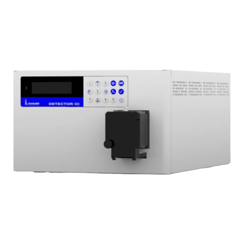
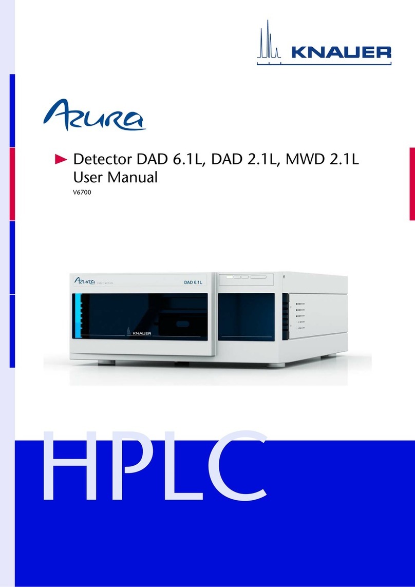
Knauer Azura ECD 2.1 User manual

HPLC
Detector ECD 2.1
Instructions
Document No. V6685

Note: For your own safety, read the instructions and observe the warn-
ings and safety information on the device and in the instructions. Keep
the instructions for future reference.
Note: In case you require this instruction in another language, please
submit your request including the corresponding document number via
e-mail or fax to KNAUER.
Phone : +49 30 809727-111 (9–17h Central European Time)
Fax: +49 30 8015010
E-Mail: support@knauer.net
Languages: German, English
KNAUER Wissenschaftliche Geräte GmbH
Hegauer Weg 38
14163 Berlin
Germany
Phone: +49 30 809727-0
Fax: +49 30 8015010
Internet: www.knauer.net
E-Mail: info@knauer.net
Document number: V6685
Version number: 1.0
Release date: 2019/10/23
Original edition
The information in this document is subject to change
without prior notice. For the latest version of the instructions,
visit our website: www.knauer.net/library
For the printed versions of our instructions, we use environmentally
friendly paper from sustainable forests.
This document contains confidential information and may not be repro-
duced without written consent of KNAUER Wissenschaftliche Geräte
GmbH.
© KNAUER Wissenschaftliche Geräte GmbH 2019
All rights reserved.
AZURA® is a registered trademark of
KNAUER Wissenschaftliche Geräte GmbH.
Customer Support:
Publisher:
Version information:
Sustainability:
Copyright:

Table of contents
AZURA® Detector ECD 2.1 Instructions, V6685
Table of contents
1. General information ................................................................1
1.1 Intended use ............................................................1
1.2 WEEE directive .........................................................2
1.3 Warning symbols ........................................................3
1.4 Safety instructions .......................................................4
2. Introduction .......................................................................7
2.1 Instrument description ...................................................7
3. Installation.........................................................................9
3.1 Site preparation requirements .............................................9
3.2 Unpacking .............................................................10
3.3 Mains connection .......................................................12
3.4 PC connection..........................................................12
3.5 Software...............................................................15
3.6 HPLC fluid connections ..................................................17
4. Maintenance & shutdown...........................................................23
4.1 Maintenance ...........................................................23
4.2 Shutting down the system................................................24
5. ECD 2.1 controller .................................................................26
5.1 Introduction............................................................26
5.2 Overview of ECD 2.1 screens .............................................27
5.3 Parameters ............................................................31
5.4 ClarityChrom® ECD 2.1 control module ....................................34
5.5 Dialogue Elite ..........................................................35
6. Detection and Parameters ..........................................................36
6.1 Introduction............................................................36
6.2 Three-electrode configuration ............................................36
6.3 Internal organization ....................................................37
6.4 Dual flow cell control ....................................................37
6.5 Parameters ............................................................40
7. Noise suppression: ADF™ ..........................................................43
7.1 Introduction............................................................43
7.2 Frequency .............................................................43
7.3 Frequency of signal and noise ............................................44
7.4 Amplitude response plot ................................................46
7.5 Applying ADF in chromatography.........................................48

Table of contents
AZURA® Detector ECD 2.1 Instructions, V6685
8. Pulsed Amperometric Detection (PAD) ...............................................50
8.1 Introduction............................................................50
9. Optimization of the working potential................................................54
9.1 Introduction............................................................54
9.2 Electrochemical reactions................................................54
9.3 Hydrodynamic and scanning voltammogram ...............................55
9.4 Optimization using a voltammogram ......................................57
9.5 Construction of a hydrodynamic voltammogram ............................59
9.6 Construction of a scanning voltammogram.................................60
10. Technical data.....................................................................64
10.1 Environmental, dimensions, weight & power requirements ...................64
10.2 General ...............................................................65
10.3 DC mode ..............................................................65
10.4 PULSE mode ...........................................................66
10.5 SCAN mode ...........................................................66
11. Rear panel I/O.....................................................................67
11.1 USB B connector........................................................67
11.2 LAN connector .........................................................68
11.3 VALVE connector .......................................................68
11.4 ANALOG DATA connector ...............................................73
11.5 Digital I/O connector ....................................................76
11.6 Chassis grounding stud..................................................83
12. Functionality tests .................................................................84
12.1 Installation Qualification (IQ) .............................................84
12.2 Operation Qualification (OQ) .............................................84
13. Troubleshooting ...................................................................85
13.1 Instrument errors .......................................................85
13.2 Analytical troubleshooting ...............................................87
13.3 Dummy cell test ........................................................87
13.4 Stop flow test ..........................................................89
14. Reorders .........................................................................94
15. Index.............................................................................95

1. General information
1.1 Intended use
The ECD 2.1 is used in combination with (Ultra) High Performance Liquid
Chromatography for the electrochemical detection of suitable analytes in
liquid samples. With this technique the amount of electroactive substan-
ces in mobile phase can be quantified. The instrument can be used for
the chromatographic analysis of a wide range of electroactive analytes in
the fields of for example:
Bioanalytical analyses
Food analyses
Environmental analyses
For research purposes only. While clinical applications may be
shown, this instrument is not tested by the manufacturer to comply
with the In Vitro Diagnostics Directive.
Operation of an electrochemical detector can involve the use of hazar-
dous materials including corrosive fluids and flammable liquids. The
instrument should only be operated by users with the following expertise:
Completed degree as chemical laboratory technician or comparable
vocational training
Fundamental knowledge of liquid chromatography
Participation in an installation of the system performed by the manu-
facturer or a company authorized by the manufacturer and suitable
training on the system and chromatography software.
Knowledge and experience in the safe handling of toxic and corrosive
chemicals and knowledge of the application of fire prevention measu-
res prescribed for laboratories.
Information on safety practices is provided with your instrument and ope-
ration instructions. Before using your instrument or accessories, you must
thoroughly read these safety practices. These instructions are written for
laboratory technicians who use the detector for (U)HPLC analysis.
Unskilled, improper, or careless use of this instrument can create
fire hazards, or other hazards which can cause death, serious injury
to personnel, or severe damage to equipment and property. Obser-
ve all relevant safety practices at all times. Only use the device for
applications that fall within the scope of the specified intended use.
Else the protective and safety equipment of the device could fail.
1
AZURA® Detector ECD 2.1 Instructions, V6685

1.2 WEEE directive
All equipment of KNAUER which are subjected to the WEEE directive
shipped after August 13, 2005 are compliant with the WEEE marking
requirements. Such products are labelled with the “crossed out wheelie”,
depicted on the left site.
The symbol on the product indicates that the product must not be
disposed as unsorted municipality waste.
Collection & recycling information
Please ship the instrument back to the manufacturer (KNAUER Wis-
senschaftliche Geräte GmbH, Germany) at the end-of-life time of the
product. The manufacturer will take care of the proper disposal and
recycling of the instrument at its facilities.
Shipping address for the end-of-life products:
KNAUER Wissenschaftliche Geräte GmbH
Hegauer Weg 38
14163 Berlin
Germany
In case of questions, or if further information is required about the collec-
tion & recycling procedure, please contact your local distributor.
2General information
AZURA® Detector ECD 2.1 Instructions, V6685

1.3 Warning symbols
The following symbols are used in this guide:
This sign warns about the risk of electric shock. It calls
attention to a procedure or practice which, if not adhered
to, could result in loss of life by electrocution. Do not pro-
ceed beyond a danger sign until the indicated conditions
are fully understood and met.
The warning sign denotes a hazard. It calls attention to a
procedure or practice which, if not adhered to, could re-
sult in severe injury, loss of life or damage or destruction
of parts or all of the equipment. Do not proceed beyond
a warning sign until the indicated conditions are fully
understood and met.
The caution sign denotes a hazard. It calls attention to
a procedure or practice which, if not adhered to, could
result in damage or destruction of parts or all of the
equipment and/or erratic results. Do not proceed beyond
a cautions sign until the indicated conditions are fully
understood and met.
The biohazard sign draws attention to the fact that use of
biological materials, viral samples may carry a significant
health risk.
The toxic hazard sign draws attention to the fact that use
of toxic solvents or samples may carry a significant health
risk.
The attention sign signals relevant information. Read this
information.
The note sign signals additional information. It provides
advice or a suggestion that may support you in using the
equipment.
3General information
AZURA® Detector ECD 2.1 Instructions, V6685

1.4 Safety instructions
Adhere to the following standard quality control procedures and the
following equipment guidelines when using the ECD 2.1 detector. The
following safety practices are intended to ensure safe operation of the
instrument.
Working environment & safety
The intended use of the instrument is to detect electroactive substances
in liquid samples in combination with a (U) HPLC system in a GLP-appro-
ved environment. Operators using the system should have the appropri-
ate education an extensive understanding of GLP rules and be skilled in
the art. Use this system ONLY for the intended use. Use of the system for
any other purpose will cause unsafe situations.
System operation
To assure optimal performance of the detector we recommend that the
instrument is checked regularly and maintenance procedures are carried
out. Preventive maintenance contracts are available for that purpose.
Please contact your local distributor or the nearest sales office for more
information.
Electrical safety
The removal of protective panels on the instrument can result in exposure
to potentially dangerous voltages. Therefore, disconnect the instrument
from all power sources before disassembly.
Untrained personnel should not open the instrument, this may only be
done by authorized service engineers. Replace or repair faulty insula-
tion on power cords immediately after discovery of the fault. Check that
the actual power voltage is the same as the voltage for which the instru-
ments are wired. Make sure power cords are connected to correct voltage
sources: grounded AC power source, line voltage 100 – 240 VAC. The ins-
trument should be connected to a protective earth via a ground socket.
4General information
AZURA® Detector ECD 2.1 Instructions, V6685

The ECD 2.1 must only be used with appliances and power sources with
proper protective grounding to prevent damage through build-up of sta-
tic electricity. The power source should exhibit minimal power transients
and fluctuations. If necessary connect to a filtered mains socket.
Replace blown fuses with fuses of proper type and rating as indicated on
the rear panel and as listed in the list of accessories and spares (appendix
D). The fuse holder is integrated in the mains connector. Ensure that the
instrument is never put in operation with fuses of a different type. This
could cause fire. Only use manufacturer-supplied I/O cable(s) to connect
with other devices. Thoroughly connect shielding to common. Manufac-
turer will not accept any liability for damage, direct or indirect, caused by
connecting this instrument to devices and with cables which do not meet
relevant safety standards.
Solvents
The solvents used may be flammable, toxic or corrosive. The room in
which the system is installed should be well ventilated to prevent that
solvent vapors cause poisoning or ignite and cause a fire. Use of open fire
in the vicinity of this system must be strictly prohibited. Do not install the
system in the same room with any other equipment that emits or could
potentially emit sparks. Provide protective equipment near the instru-
ment, when solvent gets into the eyes or on the skin, it must be flushed
away immediately. Provide equipment, such eye wash stations and safety
showers, as close to system as possible. Use proper eye and skin protecti-
on when working with solvents. Additional safety requirements or protec-
tion may be necessary depending on the chemicals used in combination
with this equipment. Make sure that you understand the hazards associa-
ted with the chemicals used and take appropriate measures with regards
to safety and protection.
Sample containers (vials) should be sealed to minimize any risks related
to solvent vapor.
5General information
AZURA® Detector ECD 2.1 Instructions, V6685

Biological hazard
When you analyze biological fluids you need possible precautions and
treat all specimens as potentially infectious. Always wear protective
gloves when handling toxic or biologically infectious samples to prevent
bio hazards or hazards while working with the ECD 2.1. If necessary the
instrument must be decontaminated before decommissioning or ship-
ment of the instrument for repair to KNAUER or its representatives. When
shipped to KNAUER every instrument has to be accompanied with a de-
contamination form which should be completely filled in and signed by
the customer. Without this decontamination form the instrument will not
be processed by KNAUER (either repaired or disposed).
Waste disposal
Perform periodic leak checks on LC tubing and connections. Do not close
or block the drain in the oven compartment. Do not allow flammable and/
or toxic solvents to accumulate. Follow a regulated, approved waste dis-
posal program. Never dispose of flammable and/ toxic solvents through
the municipal sewage system.
Applications: quality control
It is recommended that you routinely run several quality control samples.
Quality control samples should represent low, average and high levels
of a compound. Make sure that quality control sample results are within
an acceptable range, and evaluate precision from day to day and run to
run. Data collected when quality control samples are out of range may
not be valid. Do not report this data until you are certain that system per-
formance is acceptable. Apart from use of quality control samples, we
recommend that you use blanks. The blanks will help you assess whether
carry-over is within an acceptable range and monitor the integrity of your
data.
Using the ECD 2.1 in other ways than indicated in the instructions or
defined by good laboratory practice may result in erratic or unsafe
operation.
6General information
AZURA® Detector ECD 2.1 Instructions, V6685

2. Introduction
Congratulations on your purchase of the AZURA® Detector ECD 2.1. This
detector enables you to perform all (U)HPLC applications using electro-
chemical detection. The ECD 2.1 includes a highly stable Faraday-shiel-
ded oven compartment accommodating column and flow cell. This flow
cell has surprised researchers for its unsurpassed S/N ratio and therefore
you now possess the best possible combination for extremely sensitive
EC analyses. The ECD 2.1 has 3 operational measurement modes: DC,
SCAN and PULSE mode. Furthermore, a Service, Diag(nostics) and Con-
fig(uration) mode are available. In addition, crucial parameters can be
controlled by either relays or TTL. The ECD 2.1 can support up to 4 flow
cells (optional), which makes it possible to perform 4 independent mea-
surements with one detector.
These instructions cover the installation, set-up and operation of the
AZURA® Detector ECD 2.1 only. Detailed operation instructions for
other peripheral LC equipment and parts such as flow cells, pumps,
auto samplers, valves, column heaters etc. are given in the instruc-
tions accompanying those accessories. From this point onwards the
abbreviation ECD 2.1 will be used.
2.1 Instrument description
Legend
1
Instrument housing
2
LC tubing inlet/outlet
3
Instrument door panel
4
4 x 40 Ch LCD display
5
Function keys
6
<Enter> key
7
‚+‘ and ‚-‘ value keys
8
Cursor keys
9
Door handle (for opening
door)
Fig. 1 Front view
!
"
#
$
%
&
/
(
)
7
AZURA® Detector ECD 2.1 Instructions, V6685

Legend
1
Instrument rear panel
2
Type label (pn, sn etc.)
3
Digital I/O connector
(25-pins sub-D fem)
4
Analog data
(9-pins sub-D fem)
5
Valve connector (9-pins
sub-D male)
6
LAN connector
(RJ45 jack)
7
USB connector (USB B)
8
Fuse & power rating
9
Mains switch/inlet
bl Grounding stud
bm Fuse compartment
bn Ventilation holes
Fig. 2 Rear view
Legend
1
Cell cabinet
2
Cell connector
(9-pins sub-D fem)
3
Top fan heater (intake)
4
Door sensor
5
Mounting plate
(for cells & columns)
6
Door lock
7
Flow cell clamp
(for SenCell)
8
Column clamp
9
Mounting hole
for cell clamp (M4)
bl Bottom fan heater
(exhaust)
bm Mounting hole for
column clamp (M3)
bn Fuse compartment
bo Door panel, rear
bp Type label
Fig. 3 Oven compartment view
!
"
#
$
%
&
/
$
&
(
)
bl
bm
bn
bo
bp
8Introduction
AZURA® Detector ECD 2.1 Instructions, V6685

3. Installation
3.1 Site preparation requirements
For a successful onsite installation of the instrument, please arrange the
following requirements at your location in advance:
Personal Computer
In case the instrument is used via remote control by PC software (Dialo-
gue Elite, ClarityChrom®) or firmware (FW) update needs to be perfor-
med a desktop computer is required with the following requirements:
Free LAN port (onboard, PCI, PCI express or PCI-X)
Free USB port (required for FW updates)
Microsoft Windows 7 Operating System or higher
Detailed information about the use of the ECD 2.1 in combination with
ClarityChrom® chromatography software are listed in the ClarityChrom®
instructions (document no. V1670, Website:
www.knauer.net/cc-instructions) and in the list of supported drivers and
software packages for all KNAUER devices (document no. V1667, Web-
site: www.knauer.net/softwarecontrol).
Laboratory requirements
Your instrument is intended for indoor use only in an industrial or com-
mercial environment (EN55011 group 1 class A ISM equipment). It is
suitable for the following categories: Installation category II, Pollution
degree 2, equipment class I.
Table I. Environmental specifications
Parameter Requirement
Operating temperature 10 – 40 °C (50 – 104 °F)
Operating humidity 20 – 80%, non-condensing
For optimum analytical performance it is recommended that the am-
bient temperature of the laboratory is between 20-25 °C and is held
constant to within ± 2 °C throughout the entire working day.
Note: for optimal temperature stability of the cell cabinet the oven
temperature should be set to a temperature at least 7 degrees hig-
her as ambient temperature.
9
AZURA® Detector ECD 2.1 Instructions, V6685

Requirements for the laboratory bench on which the instrument will be
installed:
Stabile, clean, flat and smooth surface.
Enough mechanical strength to hold at least the weight of the detec-
tor: a full-dressed detector with flow cells, columns and valves can
weigh up to 20 kg.
A detector has the following dimensions 44 (D) x 22 (W) x 43 (H) cm =
17.3” (D) x 8.7” (W) x 16.9” (H). Take into account that additional space
is necessary on all sides (at least 10 cm) to prevent obstruction of venti-
lation holes and allow sufficient heat dissipation.
Chemicals
Mobile phase and flush/storage solutions must be clean as it is in di-
rect contact with the working electrode in EC detection. High purity of
chemicals including water is a prerequisite. So all chemicals should be
electrochemically clean, HPLC grade or better. For water used for the
preparation of mobile phases a water purification apparatus is advised
which is able to supply high purity deionized water with resistivity of >18
MOhm.cm and low TOC level (<10 ppb).
3.2 Unpacking
Inspect the transport box for possible damage as it arrives. Immediately
inform the transport company in case of damage, otherwise it may not
accept any responsibility. Keep the transport box as it is designed for op-
timum protection during transport and it may be needed again. Carefully
unpack the system and inspect it for completeness and for possible da-
mage. Contact your supplier in case of damage or if not all marked items
on the checklist are included. Prior to shipment, your detector has been
thoroughly inspected and tested to meet the highest possible demands.
The results of all tests are included.
1 Delivery is in accordance with order
2 Delivery is undamaged
3 All items on checklist(s) are included
4
Certificates of performance are included:
- detector
- flow cell(s)*
5 Printed version of instructions included
*) Note that flow cells are not part of the detector and have to be ordered separately.
10 Installation
AZURA® Detector ECD 2.1 Instructions, V6685

To unpack the detector, lift it from its box by both hands (Fig. 4). Never
lift the detector at its front door, but at its sides.
Fig. 4 Lift instructions
With both hands under the instrument lift the detector to its operation
location. Install the detector in an area which meets the environmental
conditions.
Fig. 5 Location of power supply fan
Remove the protective tape from the detector LCD screen. Leave the
instrument to adopt ambient temperature for at least half an hour in the
place of installation.
Use the detector indoors only. Place the detector upright (on its ins-
trument feet) on a stable, flat and smooth surface. Do not place the
instrument in an area subject to excessive dust or shocks.
Do not place it near a source of heat or in direct sun light, as this
may influence the heating capabilities of the instrument. Make sure
the detector is placed in such a way that the mains power connec-
tion can be reached easily to disconnect it from the mains power by
removing the mains power cable. Do not block the ventilation holes
at the back of the instrument and do not block the fan located at
the bottom of the detector (Fig. 5). Blocking the fan will impair the
cooling capability of the power supply.
11Installation
AZURA® Detector ECD 2.1 Instructions, V6685

Do not place object/instruments on top of the detector. Objects can be
placed on any side of the detector; however, make sure these objects are
placed at a distance of 5 cm from the detector, in case that objects are
placed at only one side of the instrument. and 10 cm from the instrument,
if objects are placed on both sides of the instrument.
3.3 Mains connection
Check that fuses and voltage range on the rear side of the instrument
match that for the power outlet to be used.
This device complies with the requirements of EN 55011 group 1
class A ISM equipment. In a domestic environment this product may
cause radio interference in which case the user may be required to
take adequate measures on his own expenses. Understanding power
surges. Power surges, line spikes, and transient energy sources can
impede instrument operation. Ensure that the instrument's electrical
supply is adequately protected from these conditions and properly
grounded. If necessary connect the instrument to a filtered mains
inlet.
Power supply and protective earth: The system must be connected
to a suitable mains power supply with a correctly installed protective
earth conductor. Never use the system without a properly connected
protective earth conductor.
Leave the instrument powered off until specifically mentioned in the pro-
cedure below.
3.4 PC connection
Follow the instructions in this paragraph when the instrument is used with
PC control over LAN using the Dialogue Elite or ClarityChrom® Chroma-
tography Software. This section can be skipped if the instrument is used
stand-alone. To be able to communicate over LAN a computer is required
with a free (PCI, PCI Express or PCI-X) LAN port.
The ECD 2.1 has a fixed IP address: 192.168.5.1, with subnet mask:
255.255.255.0. Gateway and DNS are not filled in.
The instrument is standard delivered with a special crossover LAN (UTP)
cable which is part of the ECD 2.1 accessory kit that is shipped with the
detector.
To insure stable and error-free communication only use the manufac-
turer-supplied LAN connectivity kit to connect the ECD 2.1 to LAN.
Create a small dedicated local area network to connect the ECD 2.1
to the PC. Do not connect the ECD 2.1 over a company Local Area
Network. If needed a second network adapter with a different (uni-
que) IP address range can be applied.
12 Installation
AZURA® Detector ECD 2.1 Instructions, V6685

In the following section the procedure to connect the instrument to the
PC using the crossover UTP cable is described. Configure the IP address
of the PC LAN network card by executing the following steps (in this
example Windows 7 OS is used, in Windows 8 the example screens may
look different):
1. Right click on the Network icon in the bottom right of the Windows
taskbar and open the menu ‚Open Network and Sharing Center‘.
Alternative: open Windows start menu, open control panel and go to
‚Open Network and Sharing Center‘):
Fig. 6 Open Network and Sharing Center
2. Open the menu ‚Change adapter settings‘ on the left panel of the
‚Open Network and Sharing Center‘ window.
3. Right click on the Local Area Connection icon of the LAN card in your
PC and click on properties to open the Network card setting.
Fig. 7 LAN properties
13Installation
AZURA® Detector ECD 2.1 Instructions, V6685

14 Installation
AZURA® Detector ECD 2.1 Instructions, V6685
Fig. 8 Internet protocol menu
4. Open the menu ‚Internet Protocol Version 4 (TCP/IPv4)‘ menu (double
click).
5. Configure the network IP address and subnet mask as depicted in the
screen dump below (IP 192.168.5.10, Subnet mask: 255.255.255.0).
Gateway and DNS fields are not filled.
6. Close the menu(s) by clicking the ‚OK‘ buttons. The network IP ad-
dress of the LAN network card is now set up for communication with
the ECD 2.1.
7. Connect the crossover (UTP) cable to the RJ45 Jack of the LAN card
of your PC (typically located on the backside of a desktop PC).
8. Connect the other end of the crossover LAN (UTP) cable to the LAN
port on the rear panel of the ECD 2.1 as depicted on the photograph.
9. Switch on the ECD 2.1. Set the detector temperature to 35 °C if a
Performance Verification (PV) will be executed, or set it to the tempe-
rature at which your application is running. Allow the instrument to
stabilize for at least one hour before starting analysis.
Functionality tests like OQ and PV are described in separate instruc-
tions. Please contact the Customer Support for more information.

15Installation
AZURA® Detector ECD 2.1 Instructions, V6685
Fig. 9 Example of LAN connection between PC and ECD 2.1. A direct
connection requires the special crossover UTP cable delivered in the
detector ship kit. With a Ethernet switch any regular UTP cable can be
used.
3.5 Software
The ECD 2.1 can be used remote in combination with PC control soft-
ware. Currently, there are two software packages available for control of
the ECD 2.1 electrochemical detector:
Elite Dialogue software from Antec, The Netherlands.
ClarityChrom® Chromatography software (Version 6.x and higher)
from DataApex, Czech
The Elite Dialogue software is also required for the upload of new firm-
ware (= embedded software controlling the ECD 2.1 electronics). In
this section the installation and configuration of the ECD 2.1 is shortly
described. Note: this is by no means a replacement of the installation
documentation available for the software packages. Please refer to this
documentation for details.
Ensure you have Administrator access rights in your system before
you start with the installation of the software packages. Elite Dia-
logue and ClarityChrom® users must have read/write access to all
software folders and subfolders.

16 Installation
AZURA® Detector ECD 2.1 Instructions, V6685
Dialogue Elite
To install the software:
Download the latest version of the Dialogue Elite from the Antec web-
site www.myantec.com (register to get access).
Double click on the setup.exe file to start the installation wizard.
Follow the instructions of the installation wizard for successful installa-
tion of the software.
Insert the Dialogue Elite license dongle to get full access to the soft-
ware (without dongle it will operate in demo mode).
Make sure that the LAN connection is configured and the LAN cable is
connected.
Power up the detector by means of the mains switch on the rear panel.
Start the program Dialogue Elite from the Windows start menu.
During start-up the ‘Select devices’ menu will pop-up as shown in
Fig. 10.
Fig. 10 Dialogue Elite: Select devices
When a ECD 2.1 detector is available it is automatically detected and
the IP address is shown in the port settings box. If not press port scan
or type in the default IP address 192.168.5.1.
The pull down field shows all responding devices with their IP and
MAC address. In case of doubt check the device unique MAC address
on the rear panel IO connector.
Type OK. The instrument will connect and is ready for use.
Table of contents
Other Knauer Security Sensor manuals
Popular Security Sensor manuals by other brands

Whadda
Whadda WPSE320 user manual

SICK
SICK M4000 Advanced operating instructions

ESYLUX
ESYLUX MD-W200i Installation and operating instructions

Honeywell
Honeywell FlexGuard 5853AP installation instructions

ATIM
ATIM LTEM user guide

PCB Piezotronics
PCB Piezotronics TORKDISC 5302D-01A/012AC080AT Installation and operating manual