WARNING
This product must be disconnected from the circuit if subjected to any high voltage or insulation
resistance testing. Irreparable damage will occur if this instruction is not followed
Fig. 2
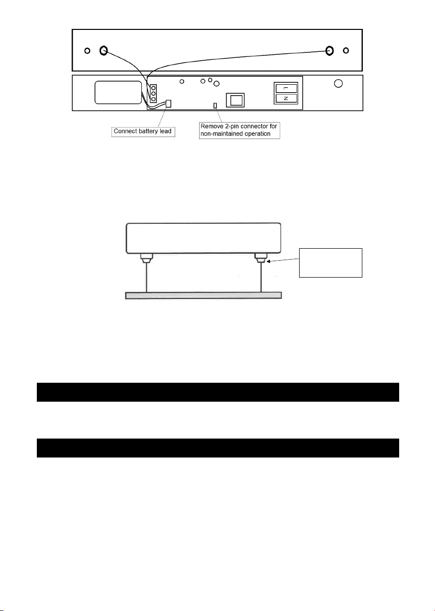
• Connect the battery lead to the battery connector on the PCB (see Fig. 2)
• Refit the cover to the top plate and secure with the two screws
• Switch on and check for correct operation, ensuring the green indicator LED is illuminated
• The height of the sign can be adjusted via the compression clamp on the luminaire (see Fig. 3). The
maximum overall length from the ceiling to the lower edge of the fitting is 800mm.
Fig. 3
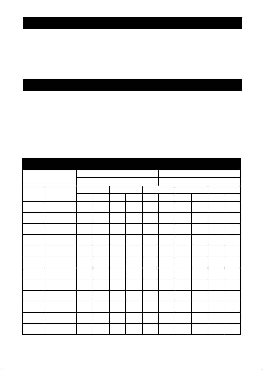
• On commissioning the installation, a minimum charge period of 24 hours is recommended before
carrying out an emergency duration test.
• The test button on the underside of the top cover of the luminaire can be used to simulate a power
failure, to test the lamp and battery operation. This can be used to carry out monthly functional
testing (see below). The fitting will switch into battery mode while the test button is held in
WARNING
This product must be disconnected from the circuit if subjected to any high voltage or insulation resistance
testing. Irreparable damage will occur if this instruction is not followed
GENERAL
This product should be recycled in the correct manner when it reaches the end of its life. Check local authorities
for where facilities exist
If the batteries have been left in a discharged state for an extended period, we recommend that one or more
charge and discharge cycles are completed which should help to restore the battery capacity
The batteries in this luminaire are Nickel Cadmium and must be disposed of correctly. Please contact local
authorities for the disposal of this toxic waste
Press this part of
the clamp to adjust
the length
• Connect the battery lead to the battery connector on the PCB (see Fig. 2)
• Refit the cover to the top plate and secure with the two screws
• Switch on and check for correct operation, ensuring the green indicator LED is illuminated
• The height of the sign can be adjusted via the compression clamp on the luminaire (see Fig. 3).
The maximum overall length from the ceiling to the lower edge of the fitting is 800mm.
Fig. 2
Fig. 2
• Connect the battery lead to the battery connector on the PCB (see Fig. 2)
• Refit the cover to the top plate and secure with the two screws
• Switch on and check for correct operation, ensuring the green indicator LED is illuminated
• The height of the sign can be adjusted via the compression clamp on the luminaire (see Fig. 3). The
maximum overall length from the ceiling to the lower edge of the fitting is 800mm.
Fig. 3
• On commissioning the installation, a minimum charge period of 24 hours is recommended before
carrying out an emergency duration test.
• The test button on the underside of the top cover of the luminaire can be used to simulate a power
failure, to test the lamp and battery operation. This can be used to carry out monthly functional
testing (see below). The fitting will switch into battery mode while the test button is held in
WARNING
This product must be disconnected from the circuit if subjected to any high voltage or insulation resistance
testing. Irreparable damage will occur if this instruction is not followed
GENERAL
This product should be recycled in the correct manner when it reaches the end of its life. Check local authorities
for where facilities exist
If the batteries have been left in a discharged state for an extended period, we recommend that one or more
charge and discharge cycles are completed which should help to restore the battery capacity
The batteries in this luminaire are Nickel Cadmium and must be disposed of correctly. Please contact local
authorities for the disposal of this toxic waste
the clamp to adjust
Fig. 3
• On commissioning the installation, a minimum charge period of 24 hours is recommended
before carrying out an emergency duration test.
• The test button on the underside of the top cover of the luminaire can be used to simulate
a power failure to test the lamp and battery operation. This can be used to carry out monthly
functional testing (see below). The fitting will switch into battery mode while the test button is
held in
GENERAL
This product should be recycled in the correct manner when it reaches the end of its life. Check
local authorities for where facilities exist
If the batteries have been left in a discharged state for an extended period, we recommend that
one or more charge and discharge cycles are completed which should help to restore the battery
capacity
The batteries in this luminaire are Nickel Cadmium and must be disposed of correctly. Please
contact local authorities for the disposal of this toxic waste
Clean with a soft dry cloth only, do not use aggressive cleaning products or solvents which may
damage the product
This product is non-dimmable 3