Knightsbridge EMLREC Instruction Manual

INSTALLATION & MAINTENANCE MANUAL
EMLREC

These instructions should be read carefully and retained after installation by the end user for
future reference and maintenance.
These instructions should be used to aid installation of the following product:
EMLREC
GENERAL INSTRUCTIONS
• This product must be installed in accordance with the latest edition of the IEE Wiring Regulations (BS 7671)
and current Building Regulations. If in any doubt, consult a qualified electrician.
• Please isolate mains prior to installation or maintenance
• Check the total load on the circuit (including when this luminaire is fitted) does not exceed the
rating of the circuit cable, fuse or circuit breaker
• Please note the IP (Ingress Protection) rating of this luminaire when deciding the location for
installation
• This product is Class II double insulated
• This product is IP20 rated
SAFETY
INSTALLATION
• Provide power to the required point of installation
• Cut a suitable aperture in the ceiling as per the cut-out details in Fig. 1 ensuring that it does not infringe with
electrical cables, water/gas pipes, or ceiling joists
Fig. 1
310mm
48mm

• Feed the mains cable through the cable entry hole in the top cover
• Connect the mains cable into the push-fit terminal block ensuring correct polarity is observed. Live (brown),
Neutral (blue)
• For non-maintained operation, remove the 2-pin connector from the circuit board (see Fig. 3). For
maintained operation, leave it in place. This fitting cannot be connected for switched maintained operation
• Remove the two screws on top of the fitting (see Fig. 2) and remove the top cover
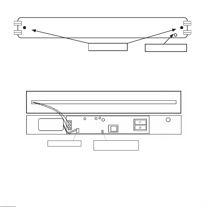
Fig. 2 Remove screws Cable entry point
Fig. 3
• Connect the battery lead to the battery connector on the PCB (see Fig. 3)
• Refit the top cover and install into ceiling aperture
• Switch on and check for correct operation, ensuring the green indicator LED is illuminated
• On commissioning the installation, a minimum charge period of 24 hours is recommended before
carrying out an emergency duration test.
• The test button on the side of the luminaire can be used to simulate a power failure, to test the lamp
and battery operation. This can be used to carry out monthly functional testing (see below). The
fitting will switch into battery mode while the test button is held in
WARNING
This product must be disconnected from the circuit if subjected to any high voltage or insulation resistance
testing. Irreparable damage will occur if this instruction is not followed
GENERAL
This product should be recycled in the correct manner when it reaches the end of its life. Check local authorities
for where facilities exist
If the batteries have been left in a discharged state for an extended period, we recommend that one or more
charge and discharge cycles are completed which should help to restore the battery capacity
The batteries in this luminaire are Nickel Cadmium and must be disposed of correctly. Please contact local
authorities for the disposal of this toxic waste
Clean with a soft dry cloth only, do not use aggressive cleaning products or solvents which may damage the
product
WARRANTY
This product has a warranty of 3 years (excluding battery) from date of purchase. Failure to install this product in
accordance with the current edition of the IEE Wiring Regulations, improper use, or removal of the batch codes
will invalidate the warranty. If this product should fail within its warranty period it should be returned to the place
of purchase for a free of charge replacement. ML Accessories does not accept responsibility for any installation
costs associated with the replacement product. Your statutory rights are not affected. ML Accessories reserve the
right to alter product specification without prior notice.
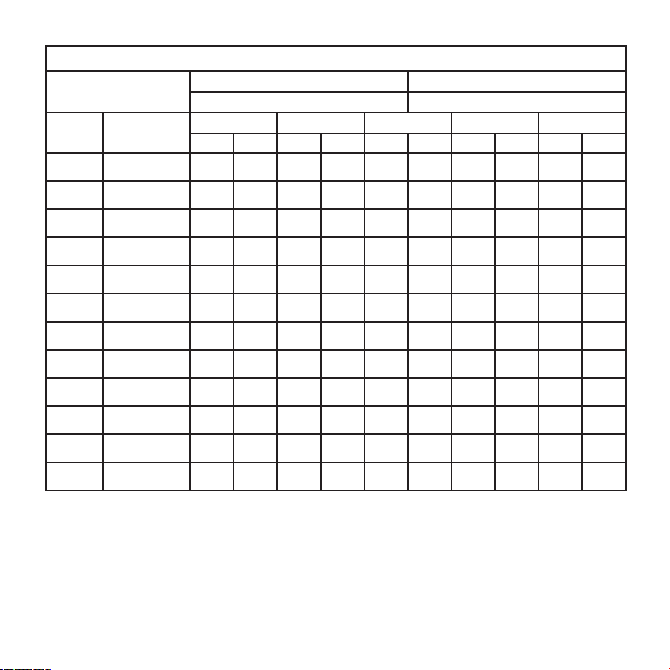
TESTING FOR EMERGENCY LUMINAIRES
Recommended routine test procedure in accordance with BS5266
• Daily check – check LED charge indicator is illuminated
• Monthly functional test – simulate a mains supply failure for approx. 30 seconds by operation of key
switch or switching off circuit breaker. Ensure normal supply is restored after test and ensure charge
indicator is illuminated
• Connect the battery lead to the battery connector on the PCB (see Fig. 3)
• Refit the top cover and install into ceiling aperture
• Switch on and check for correct operation, ensuring the green indicator LED is illuminated
• On commissioning the installation, a minimum charge period of 24 hours is recommended before carrying
out an emergency duration test
Fig. 3
Connect battery lead Remove 2-pin connector
non-maintained operation

WARRANTY
This product has a warranty of 3 years (excluding battery) from date of purchase. Failure to install this product
in accordance with the current edition of the IEE Wiring Regulations, improper use, or removal of the batch
codes will invalidate the warranty. If this product should fail within its warranty period, it should be returned to
the place of purchase for a free of charge replacement. ML Accessories does not accept responsibility for any
installation costs associated with the replacement product. Your statutory rights are not affected. ML Accessories
reserve the right to alter product specification without prior notice.
GENERAL
WARNING
This product must be disconnected from the circuit if subjected to any high voltage or insulation
resistance testing. Irreparable damage will occur if this instruction is not followed
The light source of this luminaire is not replaceable; when the light source reaches its end of life the whole
luminaire should be replaced.
Clean with a soft dry cloth only, do not use aggressive cleaning products or solvents which may damage the
product.
This product is non-dimmable.
This product should be recycled in the correct manner when it reaches the end of its life. Check local authorities
for where facilities exist.
The batteries in this luminaire are Nickel Cadmium and must be disposed of correctly. Please contact the local
authorities for the disposal of this toxic waste.
• If the batteries have been left in a discharged state for an extended period, we recommend that one or more
charge and discharge cycles are completed which should help to restore the battery capacity
• The test button on the side of the luminaire can be used to simulate a power failure to test the lamp and
battery operation. This can be used to carry out monthly functional testing (see below). The fitting will switch
into battery mode while the test button is held in

DCSEP21_V3
ML Accessories Limited LU5 4LT
www.mlaccessories.co.uk
54
INTERNATIONAL
CONTACT DETAILS
INTERNATIONAL
CONTACT DETAILS
INTERNATIONAL
CONTACT DETAILS
0~
45°C
TA
Recommended routine test procedure in accordance with BS5266
• Daily check – check LED charge indicator is illuminated
• Monthly functional test – simulate a mains supply failure for approx. 30 seconds by operation of key switch
or switching off circuit breaker. Ensure normal supply is restored after test and ensure charge indicator is
illuminated
• Annual three-hour duration test - simulate a mains supply failure for a three-hour continuous test by
operation of key switch or switching off circuit breaker. Ensure normal supply is restored after test and ensure
charge indicator is illuminated
• If the luminaire fails any of the above tests, please contact a qualified electrician
TESTING FOR LUMINAIRES

TEST RECORD SHEET
INITIAL COMMISSIONING
3 HOUR TEST
SIGNED DATE
MONTH TEST FIRST YEAR SECOND YEAR THIRD YEAR FOURTH YEAR FIFTH YEAR
SIGNED DATE SIGNED DATE SIGNED DATE SIGNED DATE SIGNED DATE
1FUNCTIONAL
2FUNCTIONAL
3FUNCTIONAL
4FUNCTIONAL
5FUNCTIONAL
6FUNCTIONAL
7FUNCTIONAL
8FUNCTIONAL
9FUNCTIONAL
10 FUNCTIONAL
11 FUNCTIONAL
12 3-HOUR
Installed by: Installation date:
Contact number:
Table of contents
Other Knightsbridge Safety Equipment manuals
Popular Safety Equipment manuals by other brands

SKYLOTEC
SKYLOTEC MARK 1 PLUS Instructions for use

DOCK LIFEGUARD
DOCK LIFEGUARD DOCK LIFEGUARD user guide

Guardian Fall Protection
Guardian Fall Protection Diablo 2.0 Tie-Back SRL instruction manual

Anthron
Anthron LORY WP manual

SICK
SICK deTec4 Core operating instructions

Eller
Eller CR250HV instruction manual