EMEXIT
These instructions should be read carefully and retained after installation by the end user for future reference and
maintenance.
These instructions should be used to aid installation of the following product:
EMEXIT
SAFETY
•This product must be installed in accordance with the latest edition of the IEE Wiring Regulations
(BS 7671) and current Building Regulations. If in any doubt, consult a qualified electrician.
•Please isolate mains prior to installation or maintenance
•Check the total load on the circuit (including when this luminaire is fitted) does not exceed the rating
of the circuit cable, fuse or circuit breaker
•Please note the IP (Ingress Protection) rating of this luminaire when deciding the location for
installation
•This product is Class II double insulated
•This product is IP20 rated
•This product is non-dimmable
INSTALLATION
•Provide power to the required point of installation
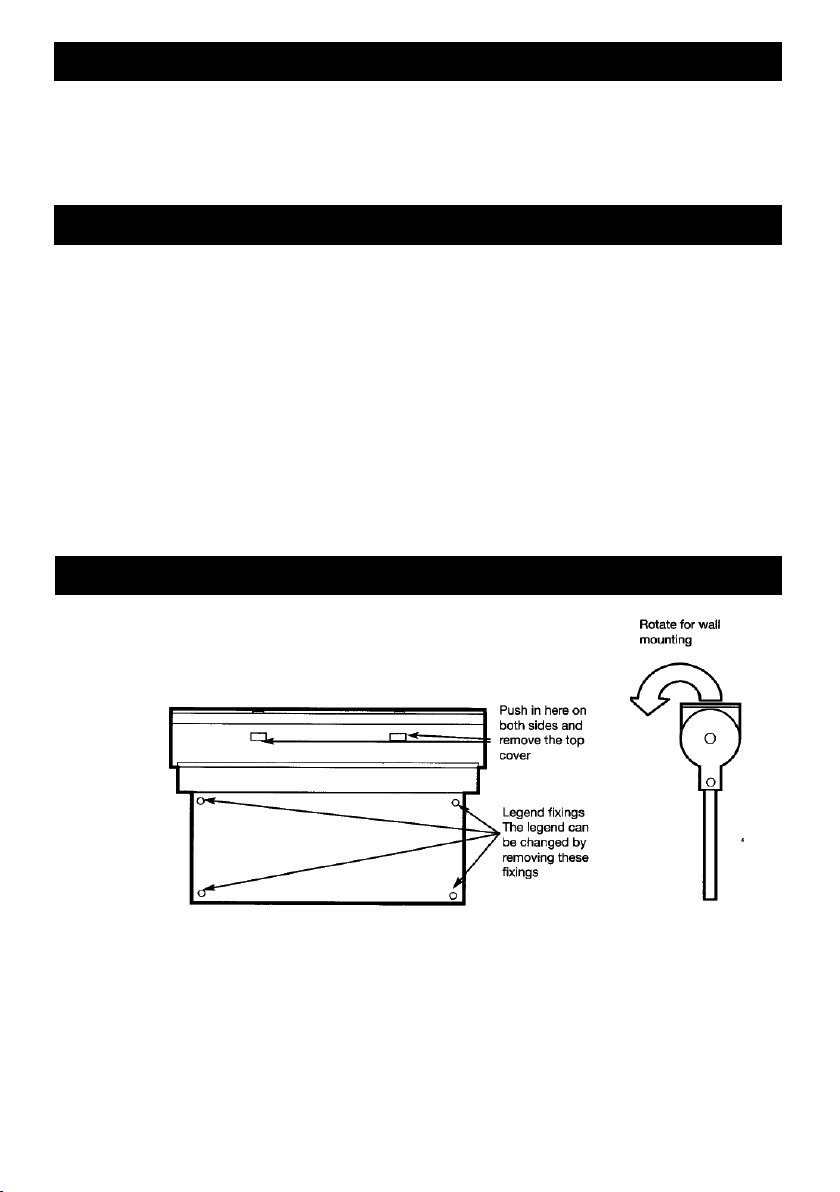
•Remove the top cover (see Fig. 1)
Fig. 1
•Using the top cover as a template, mark the location for, and drill the fixing holes ensuring not to
infringe with any gas/water pipes or electrical cables
•Feed the mains cable through the cable entry hole in the top cover
•Fix the luminaire to the surface using appropriate fixings
•Connect the mains cable into the push-fit terminal block ensuring correct polarity is observed. Live
(brown), Neutral (blue)
•For non-maintained operation, remove the 2-pin connector from the circuit board (see Fig. 2). For
maintained operation, leave it in place. This fitting cannot be connected for switched maintained
operation
EMEXIT
These instructions should be read carefully and retained after installation by the end user for future reference and
maintenance.
These instructions should be used to aid installation of the following product:
EMEXIT
SAFETY
•This product must be installed in accordance with the latest edition of the IEE Wiring Regulations
(BS 7671) and current Building Regulations. If in any doubt, consult a qualified electrician.
•Please isolate mains prior to installation or maintenance
•Check the total load on the circuit (including when this luminaire is fitted) does not exceed the rating
of the circuit cable, fuse or circuit breaker
•Please note the IP (Ingress Protection) rating of this luminaire when deciding the location for
installation
•This product is Class II double insulated
•This product is IP20 rated
•This product is non-dimmable
INSTALLATION
•Provide power to the required point of installation
•Remove the top cover (see Fig. 1)
Fig. 1
•Using the top cover as a template, mark the location for, and drill the fixing holes ensuring not to
infringe with any gas/water pipes or electrical cables
•Feed the mains cable through the cable entry hole in the top cover
•Fix the luminaire to the surface using appropriate fixings
•Connect the mains cable into the push-fit terminal block ensuring correct polarity is observed. Live
(brown), Neutral (blue)
•For non-maintained operation, remove the 2-pin connector from the circuit board (see Fig. 2). For
maintained operation, leave it in place. This fitting cannot be connected for switched maintained
operation
These instructions should be read carefully and retained after installation by the end
user for future reference and maintenance.
These instructions should be used to aid installation of the following product:
EMEXIT
GENERAL INSTRUCTIONS
SAFETY
INSTALLATION
• This product must be installed in accordance with the latest edition of the IEE Wiring
Regulations (BS 7671) and current Building Regulations. If in any doubt, please consult a
qualified electrician
• Please isolate mains prior to installation or maintenance
• Check the total load on the circuit (including when this luminaire is fitted) does not exceed the
rating of the circuit cable, fuse or circuit breaker
• Please note the IP (Ingress Protection) rating of this luminaire when deciding the location for
installation
• This product is Class II double insulated
• This product is IP20 rated
• This product is non-dimmable
• Provide power to the required point of installation
• Remove the top cover (see Fig. 1)
• Using the top cover as a template, mark the location for, and drill the fixing holes ensuring
not to infringe with any gas / water pipes or electrical cables
• Feed the mains cable through the cable entry hole in the top cover
• Fix the luminaire to the surface using appropriate fixings
• Connect the mains cable into the push-fit terminal block ensuring correct polarity is
observed. Live (brown), Neutral (blue)
• For non-maintained operation, remove the 2-pin connector from the circuit board
(see Fig. 2). For maintained operation, leave it in place. This fitting cannot be connected for
switched maintained operation
Fig.1
2