manuals.online logo
Brands
  1. Home
  2. •
  3. Brands
  4. •
  5. Knoll
  6. •
  7. Controllers
  8. •
  9. Knoll MR173 User manual

Knoll MR173 User manual

Installation and Operating
Instructions MR173 Infrared
Controller
Congratulations and thank you for choosing this
Knöll product. The MR173 is an infrared signal
controller designed to be used with the MVP64 and
Grande controller-amps as well as the Ultimo and
MR640 controllers. It is used when zones or rooms
music and sound are to be individually controlled by
an infrared receiver (and remote control) or
external computer without the use of a keypad.
Each room needing control requires an infrared
receiver, usually located in that room. Commands
from the RB8 remote control (or remotes cloned
with the RB8 commands) for each room are
detected and converted to the digital language the
controller can understand for further action.
Infrared pass through is always active with the
MR173, so most other brand remote control signals
can be used to control source equipment. In certain
installations the MR173 is used to interpret
computer generated commands for each zone or
room using an emitter output without a remote
control or infrared receiver.
Each MR173 is configured for three room inputs.
Any or all inputs can be used in an installation.
Inputs not being used can still accept keypads. The
three infrared receivers connected to the MR173
are conventional three wire styles. The MR173 can
accept up to three individual two-wire emitter
inputs. The MR173 is connected to the MVP64,
MR640 and Grande controllers by a single cat 5
wire with RJ45 connectors (not included). The
MR173 provides 12VDC power for the infrared
receivers.
Supported commands are: Power on then select
source 1, 2, 3 or 4 and set volume at about 35%;
select source 1, 2, 3, or 4; mute; unmute; volume up;
volume down, this room power off and all room
power off (hold remote power button for 5
seconds).
Installation
The MR173 should only be installed when the amp-
controller is powered off and the mains power is
unplugged. The MR173 is connected to the MR640,
MVP64 or Grande controller with a single cat 5 wire
using all 8 wire conductors and RJ45 8/8 plugs
(installer provided).
Power for the MR173 and the connected infrared
receivers is from the amp-controller and an
external power supply is not required.
Note: A 3-wire infrared receiver connected to a
MR173 and a MR60 keypad cannot both be installed
to control sound in the same room. The MR60
keypad has an infrared receiver built into it.
The MR173 can be located anywhere convenient,
usually near the controller.
Install the 3 wire infrared receivers in the room(s)
requiring them. Bring the wires to the location of
the MR173. Connect the wires from the infrared
receiver located in the first room to the blue screw
terminal labeled Room 1. V means 12VDC, G means
ground and S means signal (or to emitters). Verify
the connections.
Emitter outputs from external controllers are
connected to the S and G terminals only. If you are
connecting one or two other rooms to this MR173,
then connect the second room wires to the blue
screw terminal labeled Room 2. If you are
connecting a third room to this MR173, then
connect the third room wires to the blue screw
terminal labeled Room 3.
Lastly connect the MR173 to the controller or
controller-amp with a single cat 5 wire and RJ45
plugs, using all 8 conductors. Plug the connector into
keypad jack A1 or B1 (technically the MR173 can be
connected to any keypad jack). If the cat 5 wire
from the MR173 is plugged into A1, then the
infrared receiver wired to room 1 on the MR173 will
control the A1 outputs, the infrared receiver wired
to the room 2 on the MR173 will control the A2
outputs and the infrared receiver wired to the
room 3 on the MR173 will control the A3 outputs.
Similarly, if the cat 5 wire from the MR173 is
plugged into B1, then the infrared receiver wired to
room 1 on the MR173 will control the B1 outputs,
the infrared receiver wired to the room 2 on the
MR173 will control the B2 outputs and the infrared
receiver wired to the room 3 on the MR173 will
control the B3 outputs.
If only one or two room(s) is to be controlled by
the MR173 then the remaining two or one room(s)
can be controlled by MR60 keypads. Be sure to
select the room 2 or room 3 dipswitch on the rear
of the MR60 keypad.
Operation
The infrared receiver controlled rooms cannot do
any whole house functions except turn off the
whole system (press off button for 5 seconds). If
whole house functions are required a keypad will
have to be installed.
Turn This Room On
1. Make sure MVP64 amplifier front panel power
button is on (in) and the led color is orange or green.
Note: The RB8 remote power button is not
used to turn the system on.
2. Momentarily push the RB8 remote input button 1-4.
The RB8 remote input buttons correspond to the
MR60 source button layout and the source inputs on
the rear of the controller. After the input is initially
selected the volume always starts at about 35%.
3. If the sources don't turn on automatically, turn
them on manually or with their remote control(s).
5. Adjust the volume on the RB8 remote in this room
only.
Turn This Room or Whole House Off
1. Momentarily press the RB8 remote "POWER"
button. If this was the only room turned on, then the
whole system will shut off. If any other room was
turned on, only this room will shut off.
2. To shut down the whole system at any time, press
the RB8 remote "POWER" button for 3-5 seconds.
3. Sources may have to be turned off manually or by
remote.
Change Sources
Press another input source button on the RB8 remote
control button. The RB8 remote input buttons
correspond to the source layout of the MR60 keypads.
Volume Up and Down
Press the volume up or down button on the RB8
remote. Holding the button gives continuous changes.
Mute
Momentarily press the mute button on the RB8
remote. To restore the sound press the mute, volume
up or down, or any source or input button and the
source selected when the mute button was first
pressed is restored.
Room 1 Room 2 Room 3
MR173
RB8 Remote Control Functions
The MR173 size is 67mm x 73mm x 28mm (2.7"
x 2.9" x 1.1").
Knoll Systems Point Roberts, WA USA and
Richmond BC Canada tel: 604 272 4555
2002 Knöll Systems. All rights reserved v1.1
Power: switches
room off or whole
house off(press
for 5 seconds)
POWER MUTE
VOL
-
+43
21
INPUT
RB8
systems
Input 1-4: Turns
on room and
selects input
music source
Mute: Mutes music.
to restore, press
mute, input 1-4 or
volume up/down
Volume Up/Down
Press and hold
for continuous
volume changes

Other Knoll Controllers manuals

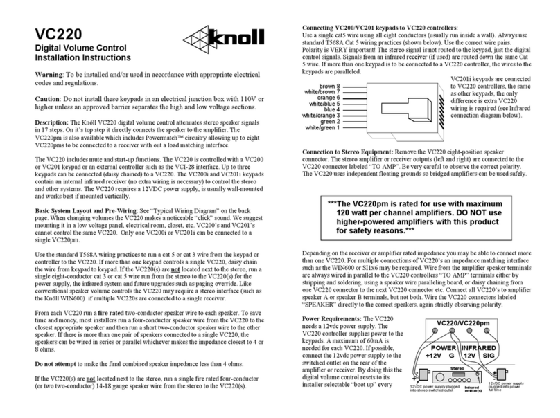
Knoll VC220PM User manual

Knoll

Knoll VC220PM User manual

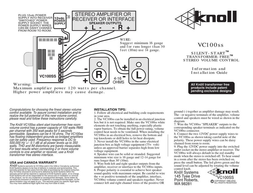
Knoll VC100SS User manual

Knoll

Knoll VC100SS User manual

Knoll VS105 User manual

Knoll

Knoll VS105 User manual

Knoll VOC120 User manual

Knoll

Knoll VOC120 User manual

Knoll VS105pm User manual

Knoll

Knoll VS105pm User manual

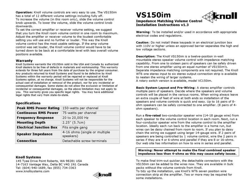
Knoll VS150im User manual

Knoll

Knoll VS150im User manual

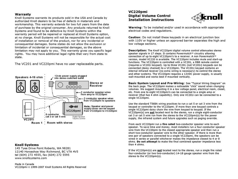
Knoll VC220PMI User manual

Knoll

Knoll VC220PMI User manual

Knoll MR200 User manual

Knoll

Knoll MR200 User manual

Knoll VC220 User manual

Knoll

Knoll VC220 User manual

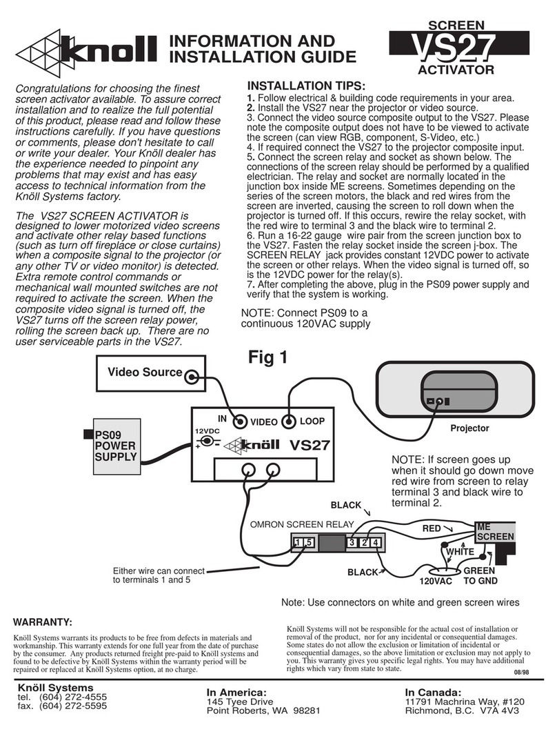
Knoll VS27 User manual

Knoll

Knoll VS27 User manual

Knoll VS100PM User manual

Knoll

Knoll VS100PM User manual

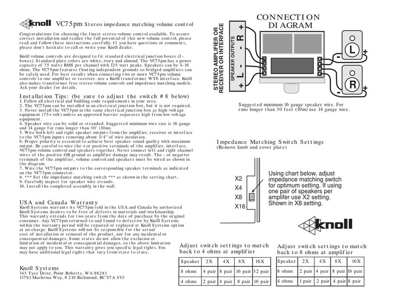
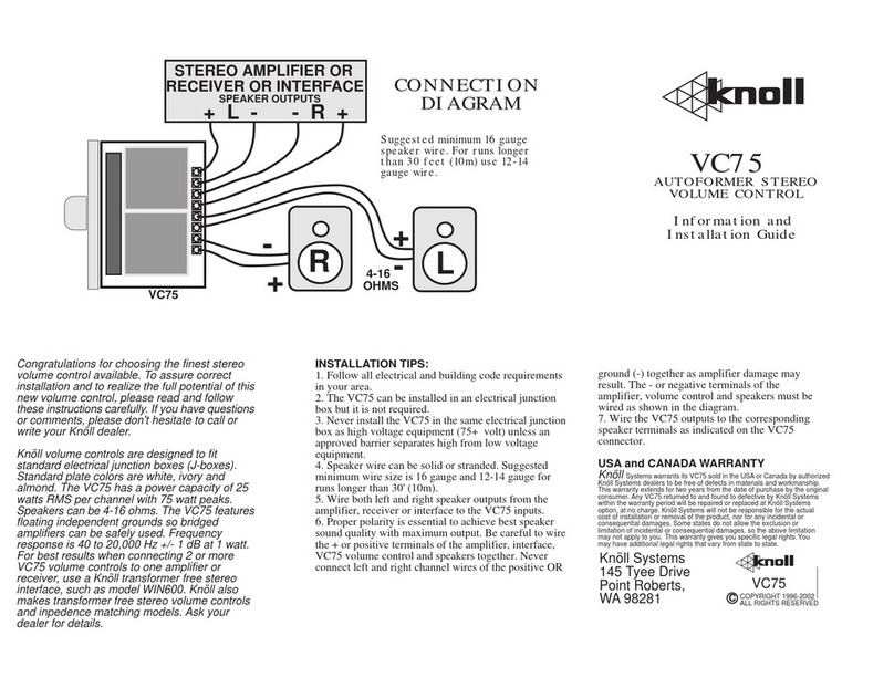
Knoll VC75 User manual

Knoll

Knoll VC75 User manual

Knoll VS100 User manual

Knoll

Knoll VS100 User manual

Knoll VC220PI User manual

Knoll

Knoll VC220PI User manual

Knoll MR640 User manual

Knoll

Knoll MR640 User manual

Knoll VC100PM User manual

Knoll

Knoll VC100PM User manual

Knoll VC100 User manual

Knoll

Knoll VC100 User manual

Knoll VC105pm User manual

Knoll

Knoll VC105pm User manual

Knoll VC220 User manual

Knoll

Knoll VC220 User manual

Knoll VC100SP User manual

Knoll

Knoll VC100SP User manual

Knoll VC75PM User manual

Knoll

Knoll VC75PM User manual

Popular Controllers manuals by other brands

Harman dbx ZC Series user guide

Harman

Harman dbx ZC Series user guide

DNF Controls 4000CL-L user manual

DNF Controls

DNF Controls 4000CL-L user manual

Mitsubishi Electric QD62 user manual

Mitsubishi Electric

Mitsubishi Electric QD62 user manual

EFI E-46A Installation and service guide

EFI

EFI E-46A Installation and service guide

Carel c.pCOMini quick start guide

Carel

Carel c.pCOMini quick start guide

CHCNAV LT60H user guide

CHCNAV

CHCNAV LT60H user guide

Sportdevices SP6 Installation and setup manual

Sportdevices

Sportdevices SP6 Installation and setup manual

Steca Elektronik Tarom MPPT 6000-M Setup guide

Steca Elektronik

Steca Elektronik Tarom MPPT 6000-M Setup guide

Mo-vis Foot Control Omni user manual

Mo-vis

Mo-vis Foot Control Omni user manual

SONIX SN8P2711A user manual

SONIX

SONIX SN8P2711A user manual

green-i GESM -AC installation guide

green-i

green-i GESM -AC installation guide

Onbon OVP-M4X user manual

Onbon

Onbon OVP-M4X user manual

HGM COMPUSHIFT II manual

HGM

HGM COMPUSHIFT II manual

ROC pH/ORP-5500 Series instruction manual

ROC

ROC pH/ORP-5500 Series instruction manual

Danfoss AFPQ 2 operating guide

Danfoss

Danfoss AFPQ 2 operating guide

Bosch HPC Installation, operation and maintenance manual

Bosch

Bosch HPC Installation, operation and maintenance manual

Full Gauge PCT-400R Plus manual

Full Gauge

Full Gauge PCT-400R Plus manual

Siemens ATC5300 operating instructions

Siemens

Siemens ATC5300 operating instructions

manuals.online logo
manuals.online logoBrands
  • About & Mission
  • Contact us
  • Privacy Policy
  • Terms and Conditions

Copyright 2025 Manuals.Online. All Rights Reserved.