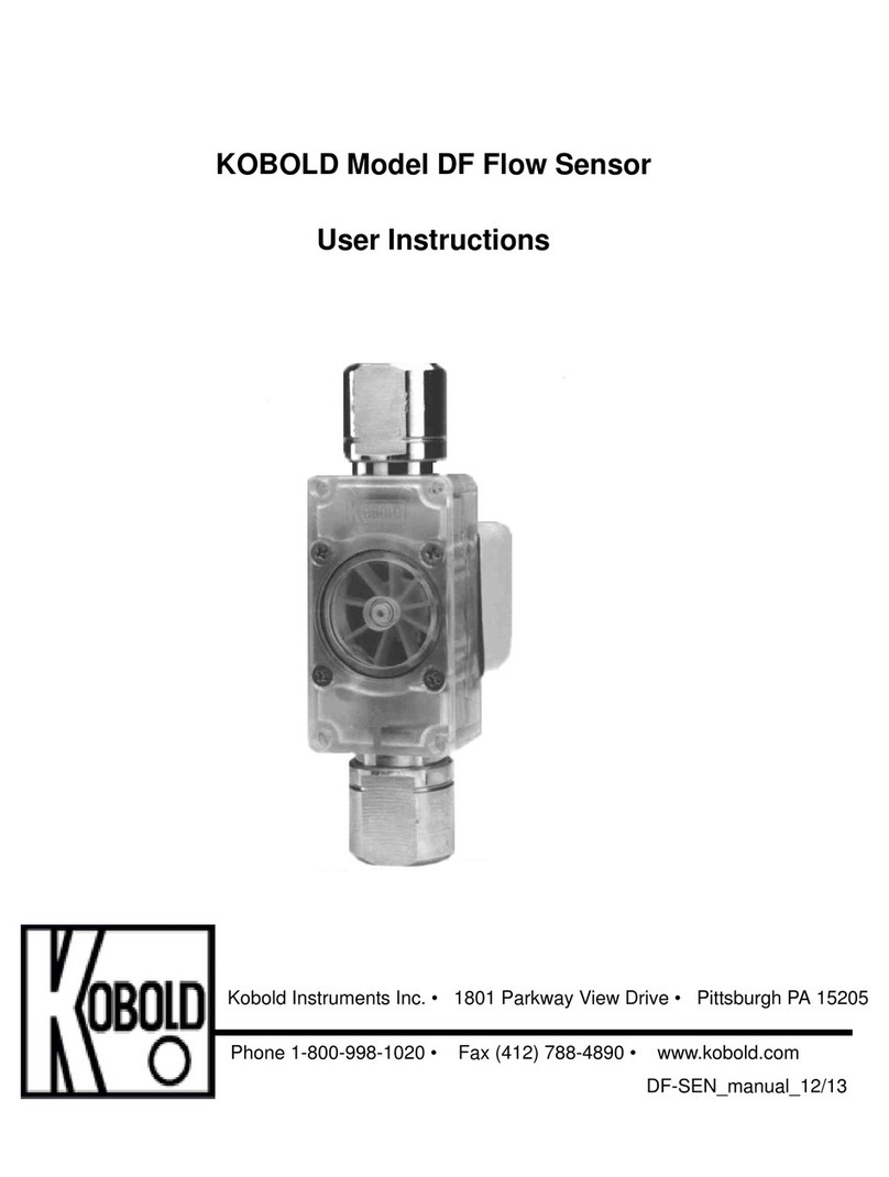
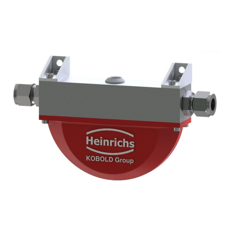
Kobold Heinrichs TM User manual

Heinrichs Messtechnik GmbHTM/TMU/TM-SH
OPERATING MANUAL FOR EXPLOSION-PROOF
FLOWMETERS
EX-Supplement MANUAL TM/TMU/TM-SH
March 2021
Coriolis mass flow sensors
TM
TMU
TM-SH
Supplementary Operating Manual for explosion-proof flow-sensors
Please read the instructions carefully and store them in a safe place

Heinrichs Messtechnik GmbH
Page 2 of 20
TM/TMU/TM-SH Supplement Manual
For Explosion Flow-meters
CONTENTS
INTRODUCTION............................................................................................................................................... 3
I. Shipping and storage; product inspection.............................................................................................................................3
II. Warranty..........................................................................................................................................................................................3
III. Validity of this operating manual.........................................................................................................................................3
1. STEPS PRIOR TO OPERATION......................................................................................................... 4
1.1Installation, mounting, commissioning and maintenance ...........................................................................................4
1.2 Hazard warnings ......................................................................................................................................................................5
1.3 Proper use of the device.........................................................................................................................................................6
2. IDENTIFICATION .................................................................................................................................. 6
2.1 Version / date............................................................................................................................................................................6
3. CORIOLIS MASS FLOW METERS..................................................................................................... 7
3.1 Description of the TM, TMU, and TM-SH sensors..........................................................................................................7
3.2 Device identification ................................................................................................................................................................7
3.2.1 TM/TMU/TM-SH rating plate......................................................................................................................................7
3.3 Mounting.....................................................................................................................................................................................8
3.3.1 Thermally insulated sensor..........................................................................................................................................8
3.3.2 Heated sensor..................................................................................................................................................................8
3.3.3 Connection remote sensor –transmitter................................................................................................................8
3.4 EC Type-Examination Certificate for the sensors type TM, TMU and TM-SH.......................................................9
3.5 Electrical Parameters...........................................................................................................................................................10
3.5.1 Exciter circuit (terminals 8 and 9)......................................................................................................................10
3.5.2 Sensor circuits (terminals 1 –2 and 3 –4)...........................................................................................................10
3.5.3 Temperature sensor circuits (terminals 5 to 7)...................................................................................................10
3.5.4 Ambient temperature range Ta ...............................................................................................................................11
3.6 Connecting the sensor to a transmitter .........................................................................................................................12
3.6.1 Connecting cables........................................................................................................................................................12
4. INSTALLATION AND COMMISSIONING.......................................................................................13
4.1 Mounting..................................................................................................................................................................................13
4.1.1 General conditions for safe operation ...................................................................................................................13
4.1.2 Requirements for installation in all environments ............................................................................................13
4.2 Ex relevant screw and bolt torques .................................................................................................................................14
5. MAINTENANCE AND REPAIR WORK ...........................................................................................15
5.1 Definition of terms according to IEC 60079-17: ..........................................................................................................15
5.2 Fault elimination....................................................................................................................................................................16
5.3 Disposal....................................................................................................................................................................................16
6. RELEVANT STANDARDS FOR HAZARDOUS LOCATIONS ......................................................17
6.1 (CSA, North America)............................................................................................................................................................17
6.2 ATEX (Europe) / IECEx ..........................................................................................................................................................17
7. EU DECLARATION OF CONFORMITY ...........................................................................................18

Heinrichs Messtechnik GmbH
TM/TMU/TM-SH Supplement Manual
For Explosion Flow-meters
Page 3 of 20
Introduction
I. Shipping and storage; product inspection
The device is to be safeguarded against moisture, dirt, impact and damage.
Product inspection
Upon receipt of the product, the consignment should be checked for completeness. The data of the device have
to be compared with the packing slip and the order documents
Notify us of any shipping damage immediately upon receipt of the product. Any damage claim received at a later
time will not be honored.
II. Warranty
Your flow sensor was manufactured in accordance with the highest quality standards and was thoroughly
tested prior to shipment. However, in the event any problem arises with your device, we will be happy to resolve
the problem for you as quickly as possible under the terms of the warranty which can be found in the terms and
conditions of delivery. Your warranty will only be honored if the device was installed and operated in accordance
with the instructions for your device. Any mounting, commissioning and/or maintenance work is to be carried
out by qualified and authorized technicians only.
III. Validity of this operating manual
The present instructions apply to explosion-proof Coriolis flow sensors of the TM/TMU and
TM-SH series, as of year of construction March 2021 or later.
These instructions are supplementary operating manual for non-explosion proof Coriolis flow
sensors. If you do not have a copy of the latter instructions, please request one from Heinrichs
Messtechnik GmbH or download the instructions from our website.
The instructions herein pertain primarily to explosion proof Coriolis flow sensors for use in conjunction with an
explosion proof certified transmitter. The technical data in the mounting and operating instructions for non-
explosion proof Coriolis flow sensors still apply insofar as the present instructions do not replace them or
exclude their application.
The transmitter used in conjunction with a TM/TMU or TM-SH sensor must be listed for use in Canada and/or
USA depending on its area of installation. The manufactures installation drawings shall be followed when
installing this equipment.
Repairs and hazardous materials
It is important that you do the following before shipping your flow sensor to Heinrichs Messtechnik GmbH for
repair:
Enclose a description of the problem with your device. Describe in as much detail as possible the application
and the physical and chemical properties of the fluid.
Remove any residues from the device and be sure to clean the seal grooves and recesses thoroughly. This
is particularly important if the fluid is corrosive, toxic, carcinogenic, radioactive or otherwise hazardous.
The operator is liable for any substance removal or personal damage costs arising from inadequate cleaning of a
device that is sent for repair.

Heinrichs Messtechnik GmbH
Page 4 of 20
TM/TMU/TM-SH Supplement Manual
For Explosion Flow-meters
1. Steps prior to operation
Prior to installation and operation, it is essential that the operator familiarizes himself
with all of the instructions and information contained in the manual for non-explosion
proof Coriolis flow meters as well as the present instructions. If any part of either manual
is missing, contact Heinrichs Messtechnik GmbH to request a new manual. These
manuals can also be downloaded from our website.
The TM, TMU and TM-SH sensors described herein are only to be used to measure liquid and gas mass and
volume flow, as well as density and temperature, in conjunction with a transmitter certified for use in the area
and country of operation, and compatible with the parameters of the sensor.
1.1 Installation, mounting, commissioning and maintenance
Installation, mounting, commissioning and maintenance are to be performed by a technician trained to work
with explosion-proof devices, or by a Heinrichs Messtechnik service technician.
Warning:
Any safety relevant maintenance or repairs in terms of explosion-protection is to be
carried out by the manufacturer, an authorized Heinrichs Messtechnik GmbH service
center or under the supervision of an expert in explosion proof devices.
Heinrichs Messtechnik GmbH accepts no liability for any loss or damage of any kind arising from improper
operation of any product, improper handling or use of any replacement part, or from external electrical or
mechanical effects, overvoltage or lightning. Any such improper operation, use or handling shall
automatically invalidate the warranty for the product concerned.
In the event a problem arises with your device, or if you need assistance in diagnosing a problem with your
device, please contact us at one of the following numbers to arrange to have your device repaired:
+49 (0)221 49708-0 +49 (0)221 49708-178
Company:
Heinrichs Messtechnik GmbH
HM-EE (R&D Department)
Robert-Perthel-Strasse 9
D-50739 Cologne
Germany

Heinrichs Messtechnik GmbH
TM/TMU/TM-SH Supplement Manual
For Explosion Flow-meters
Page 5 of 20
1.2 Hazard warnings
The purpose of the hazard warnings listed below is to ensure that device operators and maintenance personnel
are not injured and that the flow meter and any devices connected to it are not damaged.
The safety advisories and hazard warnings in the present document that aim to avoid placing operators and
maintenance personnel at risk and to avoid material damage are prioritized using the terms listed below, which
are defined as follows in regard to the instructions herein and the advisories pertaining to the device itself.
Warning
means that failure to take the prescribed precautions could result in injury, substantial material
damage or even death. Always comply to these warnings and proceed with caution.
Caution
means that failure to take the prescribed precaution could result in material damage or
destruction of the device. We advice always to abide to these instructions!
Note
means that the accompanying text contains important information about the product, handling
the product or about a section of the documentation that is of particular importance.

Heinrichs Messtechnik GmbH
Page 6 of 20
TM/TMU/TM-SH Supplement Manual
For Explosion Flow-meters
1.3 Proper use of the device
The Coriolis Mass Flow Sensor is intended for the sole use of direct and continuous mass flow measurement of
liquids and gases.
To ensure safety for people and the environment adhere to the installation and operational instructions and
warning in this manual
Warning
The operator is responsible for ensuring that the material used in the sensor and
housing are suitable and that such material meets the requirements for the process
medium and the ambient site conditions.
The manufacturer accepts no responsibility for the selection of unsuitably materials.
Caution
To ensure the device performs correctly and safely, it must be shipped, stored, set up,
mounted, operated and maintained correctly.
2. Identification
Manufacturer
Heinrichs Messtechnik GmbH
Robert-Perthel-Straße 9
D-50739 Köln
Phone: +49 221 49708-0
Fax: +49 221 49708-178
Internet: http://www.heinrichs.eu
E-mail: [email protected]
Product type
Mass flow meter for liquid and gaseous products
Product name
TM/TMU/TM-SH
Coriolis mass flow sensors
Products classes:
(North America)
CLASS 2258 04
PROCESS CONTROL EQUIPMENT –Intrinsically Safe, Entity –For
Hazardous Locations
CLASS 2258 84
PROCESS CONTROL EQUIPMENT –Intrinsically Safe, Entity –For
Hazardous Locations –Certified to US Standards
2.1 Version / date
Version: TMX-EX_NA_BA_21.01_DRAFT.DOC
Dated: 2021-03-27 (yyyy.mm.dd)

Heinrichs Messtechnik GmbH
TM/TMU/TM-SH Supplement Manual
For Explosion Flow-meters
Page 7 of 20
3. Coriolis mass flow meters
3.1 Description of the TM, TMU, and TM-SH sensors
The TM* series of sensors have an “Intrinsic safety” type of protection which is equipped with the following four
independent potential-free circuits:
Excitation circuit
Sensor circuit 1
Sensor circuit 2
Temperature sensor circuit (RTD)
All circuits within the sensor possess a safe separation.
When remote mounted, the transmitter should be connected to the sensor using a dedicated cable specially
designed for this purpose. Such a cable can be purchased from Heinrichs Messtechnik during your order
process.
Although the appearance of the standard and explosion-proof transmitters are often identical and their rating
plates contain similar information, under no circumstances should a standard (non-explosion proof) transmitter
be connected to an explosion-proof sensor!
3.2 Device identification
The rating plates on Heinrichs Messtechnik flow meters that are suitable for use in potentially explosive
atmospheres are labeled accordingly. Since the sensor and transmitter have different ratings, each device has
its own rating plate.
3.2.1 TM/TMU/TM-SH rating plate
The rating plate contains all the information necessary to identify the sensor, and for determining it’s suitability
for a potential explosive atmosphere.
Image 1: TM-T for process temperatures ranging from –20 °C to 100 °C.

Heinrichs Messtechnik GmbH
Page 8 of 20
TM/TMU/TM-SH Supplement Manual
For Explosion Flow-meters
3.3 Mounting
The mounting instructions for the standard sensor also apply to the explosion-proof sensor.
3.3.1 Thermally insulated sensor
The sensor may be outfitted with thermal insulation, also in explosive atmospheres. However, so not to impair
the junction box or connectors thermal ratings, the insulation shall only cover maximum the half of the sensors
neck onto which the junction box or connector is mounted.
3.3.2 Heated sensor
The sensor can be externally heated to avoid crystallization in the flow tube. Any heating technique or device
can be used. When using electrical heating devices, these must be suitable for use in the potentially explosive
environment present.
It is the operator’s responsibility to ensure that the heating temperature does not exceed the maximum
allowable temperature for the fluid and/or the maximum allowable temperature range for the potentially
explosive atmosphere in which the device is being operated.
The maximum allowable temperature range for the fluid is indicated on the sensors rating plate.
It is also the operator’s responsibility to ensure that no hazards are created by hot surfaces pursuant to
EN 1127-1 (Explosive atmospheres –Explosion prevention and protection) paragraphs 5.2 and 6.4.2.
3.3.3 Connection remote sensor –transmitter
A dedicated cable SLI2Y (SP) CY 5 x 2 x 0.5 mm² [blue] or similar is to be used for the electrical connection
between sensor and the remote mounted transmitter. This cable, which is available from Heinrichs
Messtechnik, has five twisted pairs, each of which has a foil shield, tinned copper mesh and filler cord. The
tinned copper meshes are installed in the “shield” terminal in both the sensor and transmitter. All 5 cable pairs
are shielded by a further tinned copper wire mesh. This external cable shield is connected to the housing via a
dedicated EMC cable fitting, thus ensuring optimum noise immunity.
Schirm / shield
10
9
8
5
7
6
4
3
2
1
-
-
-
-
-
-
-
-
-
-
rosa / pink
grau / grey
schwarz / black
violett / violett
blau / blue
rot / red
gelb / yellow
grün / green
weiß / white
braun / brown
-
-
-
-
-
-
-
-
-
-
Schirm / shield
10
9
8
5
7
6
4
3
2
1
rosa / pink
grau / grey
schwarz / black
violett / violett
blau / blue
rot / red
gelb / yellow
grün / green
weiß / white
braun / brown
Image 2: Heinrichs standard cable: SLI2Y (SP) CY 5 x 2 x 0.5
The operator is to comply in all cases with the applicable installation regulations such as EN 60079-14
“Electrical apparatus for explosive gas atmospheres- Part 14: Electrical installations in hazardous areas”.
Applicable guidelines pertaining to the interconnection of intrinsically safe circuits must also be observed.

Heinrichs Messtechnik GmbH
TM/TMU/TM-SH Supplement Manual
For Explosion Flow-meters
Page 9 of 20
The following maximum cable parameters must be abided to:
CL= 100 pF/m wire to wire
CL= 170 pF/m wire to shield
LL= 700 µH/km wire to wire
LL= 500 µH/km wire to shield
Warning
If a connecting cable other than the Heinrichs Messtechnik cable is used, the intrinsic
safety of the cable is to be validated using the cable’s nominal values
3.4 EC Type-Examination Certificate for the sensors type TM, TMU and TM-SH
The sensors are certified with the following examination certificates:
CSA (North America)
CSA18CA70171067X
Class I Division 1 and 2, Group A,B,C,D
Class I Zone 1: AEx ia TX Ga
ATEX (Europe)
DMT 01 ATEX E 149 X
II 1/2G Ex ia IIC T6-T2 Ga/Gb
IECEx (Global)
IECEx BVS 11.0084 X
Ex ia IIC T6-T2 Ga/Gb
NEPSI (CHINA)
GYJ17.1166X
Ex ia IIC T2~T6 Ga/Gb
KCS (KOREA)
12-KB4BO-0116X
Ex ia IIC T6-T2
and are approved for the use in potentially explosive atmospheres. (hazardous classified locations)
The sensor may be used in such a way that inside the measuring tubes explosive atmosphere may be present
often or for a long time (Zone 0).

Heinrichs Messtechnik GmbH
Page 10 of 20
TM/TMU/TM-SH Supplement Manual
For Explosion Flow-meters
3.5 Electrical Parameters
Warning
To ensure compliance with the requirements for explosive atmospheres, it is essential
that the maximum electrical and thermal values set forth below are observed
3.5.1 Exciter circuit (terminals 8 and 9)
3.5.1.1 For exciter circuit type EC1
Voltage Ui 30 V
Current Ii 90 mA
Power Pi 0.4 W
Effective internal capacitance Ci negligible
Effective internal inductance Li 4.38 mH
3.5.1.2 For exciter circuit type EC2
For connecting an intrinsically safe circuit with an Ex ia IIC type of protection, linear output
characteristic and the following maximum values:
Voltage Uo 30 V
Current Io 90 mA
Power Po 1 W
Effective internal inductance Li 4.38 mH < Li < 220 mH
3.5.2 Sensor circuits (terminals 1 –2 and 3 –4)
Voltage Ui DC 30 V
Current Ii 50 mA
Power Pi 0.300 W
Effective internal capacitance Ci negligible
Effective internal inductance Li 14 mH
Output voltage Uo AC 0.3 V
3.5.3 Temperature sensor circuits (terminals 5 to 7)
Voltage Ui DC 30 V
Current Ii 100 mA
Power Pi 0.333 W
Effective internal capacitance Ci negligible
Effective internal inductance Li negligible

Heinrichs Messtechnik GmbH
TM/TMU/TM-SH Supplement Manual
For Explosion Flow-meters
Page 11 of 20
3.5.4 Ambient temperature range Ta
The ambient temperature range is dependant on the type of connection, installation, process
temperature and temperature class.
For determining the prevailing temperature class at the location of installation refer to the following
tables as well as the relevant type certificate:
With HAN R23 plug
Neck extension (Between the
TM, TMU or TM-SH*sensors,
and the Harting HAN R23
Connector)
Process temp. (°C)
-50 °C to ..
Ambient temp.
range (°C)
-40 °C to ..
Temperature
class
without
40
45
T6
without
60
60
T5
60 mm
100
80
T4
160 mm
115
80
T4
160 mm
175
80
T3
160 mm
180
80
T2
260 mm
220
80
T2
CAUTION: The temperature ranges and classes printed in BOLD and Cursive, are NOT available for
installation in North America
* TM-SH sensors are restricted to Tamb = 60 °C and T process = -40°C to 60°C, see Table coils.
Remote mount configuration (Junction box)
Neck extension length
(Between the TM, or TMU
sensor neck, and the J-Box)
Sensors have a standard neck
> 60mm
Process temp. (°C)
-50 °C to ..
Ambient temp.
range (°C)
-40 °C to ..
Temperature
class
without
40
40
T6
without
60
60
T5
without
100
80
T4
100 mm
115
80
T4
100 mm
175
80
T3
100 mm
180
80
T2
200 mm
220
80
T2
CAUTION: The temperature ranges and classes printed in BOLD and Cursive, are NOT available for
installation in North America.

Heinrichs Messtechnik GmbH
Page 12 of 20
TM/TMU/TM-SH Supplement Manual
For Explosion Flow-meters
3.6 Connecting the sensor to a transmitter
The transmitter used in conjunction with a TM, TMU or TM-SH sensor must be listed for use in Canada and/or
USA depending on its area of installation. The manufactures installation drawings shall be followed when
installing this equipment.
It is essential that the output parameters of the transmitter correspond to those of the sensor.
3.6.1 Connecting cables
The connecting cables for power supply, signal outputs and sensor circuits must adhere to either the
requirements of EN 60079-14 for Europe, Section 18 of the Canadian Electrical Code for Canada or Article NEC
504 and/or NEC 505 for USA.
Note:
The connecting cables are to be installed in such a way that they are protected
against mechanical damage and unduly high temperatures.
The external diameters of the connecting cables must be compatible with the
thickness range of the cable glands and rubber seals used.
The cables and cable glands used must be compatible with the type of protection of
the junction box being used.
The dummy plugs used for unused cable glands must be compliant with the type of
protection of the housing being used.
It must be ensured that the cable gland gaskets are correctly seated..
3.6.1.1 Cable and conduit entries
Cable and conduit entries need to be certified for the type of protection of the transmitter and fit to the cables
used.
See also EN 60079-14/10.3.
3.6.1.2 Equipotential bonding
Equipotential bonding between the sensor and transmitter is essential and must be established and
maintained. Terminals are provided on the outside of the sensor and transmitter for this purpose.

Heinrichs Messtechnik GmbH
TM/TMU/TM-SH Supplement Manual
For Explosion Flow-meters
Page 13 of 20
4. Installation and Commissioning
4.1 Mounting
The mounting instructions for the standard sensor also apply to the explosion-proof sensor.
Depending on the approval of the connected transmitter, the sensor may either be:
Directly mounted, mechanically fastened to the transmitter producing a single unit.
or
Separately installed and connected with a special sensor cable, whereby the maximum CLand LL of the
connection cable must be observed.
Refer to the standard operating manual for the connection scheme of the sensor
4.1.1 General conditions for safe operation
a) If the conditions described in this document are not adhered to or if there is any inappropriate
interference with the equipment, all the manufactures warranties expire.
b) Conditions described in this manual, as well as the permitted operating conditions which have been
defined for the sensor and which are stated on the rating plates must be adhered to.
c) Appropriate measures shall be met to prevent any unintentional or inadmissible damage to the device.
d) The operator shall ensure that the equipment is only installed in areas which comply with the approved
types of protection and environments.
e) All connected electrical equipment must be suitable for its intended use.
f) The operator shall ensure protection against lightning according to local regulations.
g) For models with a junction box enclosure made from Aluminum alloy, ignition sources due to impact
and friction sparks could occur. This shall be considered during installation, the danger of objects falling
onto the sensor shall be excluded.
h) Combination of the external barriers from the transmitter has not been assessed. Therefore each
input wiring circuit to the sensors should be kept segregated from the other inputs as per
requirements of the standards.
i) For exciter coils type EC2 and EC2R the supply signal from the transmitter shall be pulsed with low duty
cycle or non-repetitive.
4.1.2 Requirements for installation in all environments
a) The installation of the intrinsically safe circuits requires a control drawing (system description), to be
issued by the operator/erector.
b) For ordinary locations installations to be supplied by a Limited Energy Source in accordance with CSA
61010-1-12/UL 61010-1.
c) The equipment is only to be installed and connected in a de-energized state.
d) The sensor is to be installed (from specialists) according to applicable regulations.

Heinrichs Messtechnik GmbH
Page 14 of 20
TM/TMU/TM-SH Supplement Manual
For Explosion Flow-meters
e) When mounted separately (remote mount configuration), equipotential bonding between the sensor
and transmitter is essential to guarantee conformity of the intrinsically safe circuits. Terminals are
provided on the outside of the sensor and transmitter for this purpose
f) It is to be ensured that the intrinsically safe circuits of the sensor cable are not laid together with non-
intrinsically safe circuits.
g) When using a connection cable other than the manufactures specified cable, the intrinsic safety of the
cable is to be validated using the cables nominal parameters. Field wiring using multi-conductor cable
shall either have each conductor pair enclosed in a grounded metal shield, or each conductor shall have
a minimum of 0.25mm (0.01”) insulation thickness.
The following maximum values apply:
Wire to wire - CL= 100pF/m LL= 0.7mH/km
Wire to shield - CL= 170pF/m LL= 0.5mH/km
h) If the sensor is used at an ambient temperature of less than -20 °C or greater 60 °C, suitable cables,
cable entries and conduit entries are to be used.
i) The operational wall thickness of the stainless steel flow tubes may be < 1 mm. In this case, the
operator is to ensure that in the area of these tubes, no risk of damage by the medium or through
mechanical damage shall occur.
j) The sensor may be used in such a way that in the measuring tubes an explosive atmosphere may be
present occasionally or for a long period of time.
k) Seized screws or adhering joints (e.g by frost or corrosion) are not to be opened with force in the
presence of a potentially explosive atmosphere.
l) Where substances of explosion group “A” or “IIC” are present and the presence of an Ex-atmosphere is
considered possible, only non-sparking tools shall be used.
m) The electrical connections from the sensor to the junction box are made by means of a connection
flange. Care must be taken to guarantee the IP protection class.
4.2 Ex relevant screw and bolt torques
Potential Equalisation fixation 6 Nm
Nuts sensor-neck/J-box (PE) 6 Nm
Screws J-box lid (Aluminium) 2 Nm
Screws J-box lid (Polyester) 1.2 Nm
Cable glands to J-box adapter 12 Nm
Cable gland caps 8 Nm

Heinrichs Messtechnik GmbH
TM/TMU/TM-SH Supplement Manual
For Explosion Flow-meters
Page 15 of 20
5. Maintenance and repair work
5.1 Definition of terms according to IEC 60079-17:
Maintenance: defines a combination of any actions carried out to retain an item in, or restore it to, conditions in
which it is able to meet the requirements of the relevant specification and perform its required functions.
Inspection: defines any action comprising careful scrutiny of an item carried out either without dismantling, or
with the addition of partial dismantling as required, supplemented by means such as measurement, in order to
arrive at reliable conclusion as to the condition of an item.
Visual inspection: defines an inspection which identifies, without the use of access equipment and tools, those
defects, such as missing bolts, which will be apparent to the eye.
Close inspection: defines an inspection which encompasses those aspects covered by a visual inspection and, in
addition, identifies those defects, such as loose bolts, which will be apparent only be the use of access
equipment, for example steps, where necessary, and tools.
Detailed inspection: defines an inspection which encompasses those aspects covered by a close inspection and,
in addition, identifies those defects, such as loose terminations, which will only be apparent by opening the
enclosure, and/or using, where necessary, tools and test equipment.
a) Maintenance or replacement work must be carried out by qualified personnel only, i.e. personnel
qualified according to TRBS 1203 or similar.
b) Only auxiliary components which comply with all North American requirements, national directives and
legislations may be used in potentially explosive atmospheres
c) At the presence of Ex-atmospheres, the equipment must be regularly cleaned. The intervals are to be
defined by the operator in compliance with the environmental rules valid at the place of operation.
d) After maintenance and repair works have been performed, all barriers and notices removed for that
purpose must be returned to their original place.
e) In the event that faults of the equipment are detected, the equipment is to be removed. The internal
components cannot be maintained by the customer. The equipment is to be returned to the
manufacturer for inspection.
f) Fuses, with the exception of the replaceable mains fuse, may not be replaced by the operator, since
affected zener-diodes must also be simultaneously replaced. This work requires a follow-up
adjustment, which can only be carried out at the manufacturer’s factory.
Activity
Visual inspection
Close inspection
Detailed inspection
3 month interval
6 month interval
12 month interval
1
Visual inspection of equipment for
intactness, removal of dust settlements
X
2
Check of electrical system for intactness
and functionality
X
3
Check of entire system
User's responsibility

Heinrichs Messtechnik GmbH
Page 16 of 20
TM/TMU/TM-SH Supplement Manual
For Explosion Flow-meters
5.2 Fault elimination
No repairs or modifications may be performed on equipment that is operated in conjunction with explosive
atmospheres. Such equipment shall only be repaired by expert personnel trained and authorized to do so.
Damaged threaded or flat joints which may impair the IP protection of the enclosure shall not be repaired or
modified. The equipment shall be returned to the manufacturer for repair and replacement.
5.3 Disposal
Packaging material and worn components shall be disposed of according to the regulations applicable in the
country of installation.

Heinrichs Messtechnik GmbH
TM/TMU/TM-SH Supplement Manual
For Explosion Flow-meters
Page 17 of 20
6. Relevant Standards for Hazardous Locations
6.1 (CSA, North America)
CAN/CSA C22.2 No. 0-10 General Requirements –Canadian Electrical Code, Part II
CAN/CSA C22.2 No. 61010-1-12 Safety Requirements for Electrical Equipment for Measurement, Control,
and Laboratory Use--Part 1: General Requirements
CAN/CSA C22.2 No. 60079-0-19 Explosive atmospheres –Part 0: General Requirements
CAN/CSA C22.2 No. 60079-11-14 Explosive atmospheres –Part 11: Equipment protection by intrinsic
safety “i”
ANSI/ISA - 60079-0:2020 Explosive Atmospheres - Part 0: Equipment - General Requirements
ANSI/ISA - 60079-11:2014 Explosive atmospheres –Part 11: Equipment protection by intrinsic
safety “i”
UL 61010-1 –3rd Edition Safety Requirements for Electrical Equipment for Measurement, Control,
and Laboratory Use - Part 1: General Requirements
6.2 ATEX (Europe) / IECEx
DIN EN 60079-0 Explosive locations: General requirements
DIN EN 60079-11 Explosive locations: Equipment protection by intrinsic safety "i"
DIN EN 60079-26 Explosive locations: Equipment with Equipment Protection Level (EPL)
Ga

Heinrichs Messtechnik GmbH
Page 18 of 20
TM/TMU/TM-SH Supplement Manual
For Explosion Flow-meters
7. EU Declaration of conformity

Heinrichs Messtechnik GmbH
TM/TMU/TM-SH Supplement Manual
For Explosion Flow-meters
Page 19 of 20

Heinrichs Messtechnik GmbH
Page 20 of 20
TM/TMU/TM-SH Supplement Manual
For Explosion Flow-meters
This manual suits for next models
2
Table of contents
Other Kobold Accessories manuals

Kobold
Kobold KET User manual

Kobold
Kobold DF-**01 series User manual

Kobold
Kobold SEN-33 Series User manual

Kobold
Kobold PMP User manual

Kobold
Kobold HND-PS19 PS33 Series User manual

Kobold
Kobold LTS-A User manual

Kobold
Kobold AFK-A User manual

Kobold
Kobold SEN-9601 User manual

Kobold
Kobold SEN-86 Series User manual

Kobold
Kobold SEN-9601 User manual