SEN-86../87..
page 8 SEN-86../87.. K04/0618
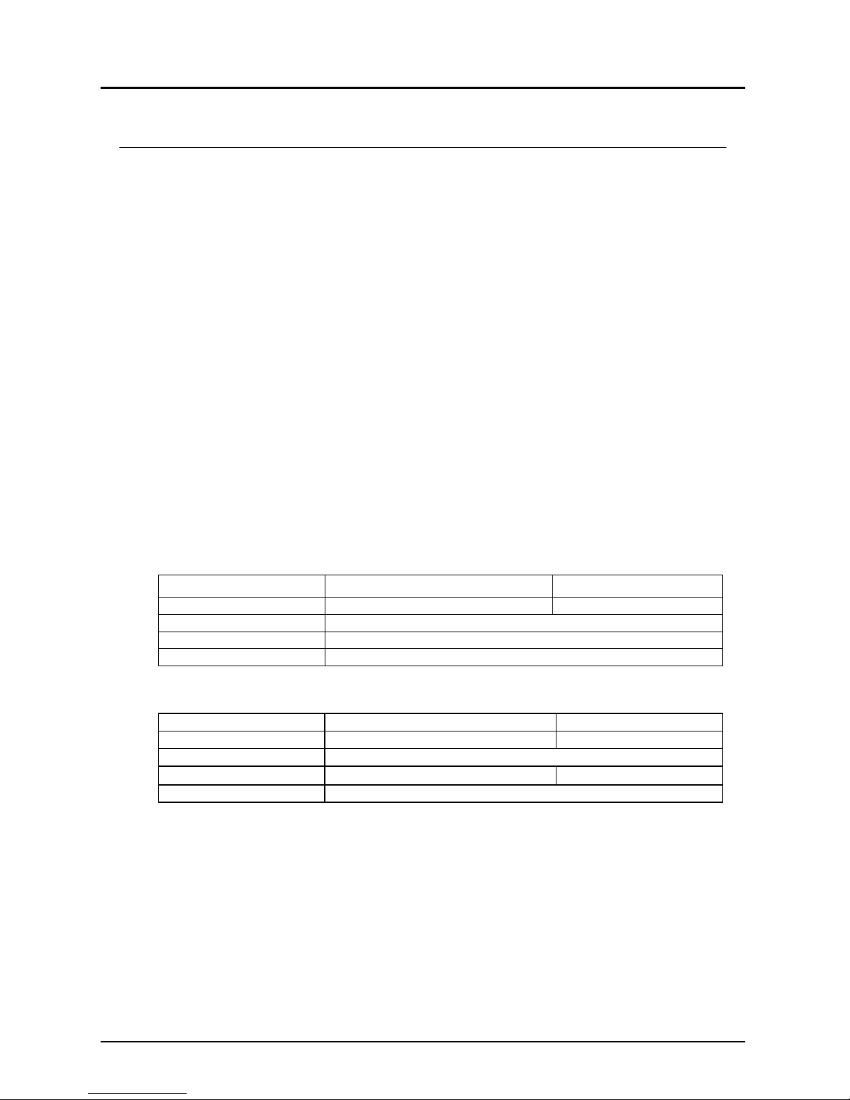
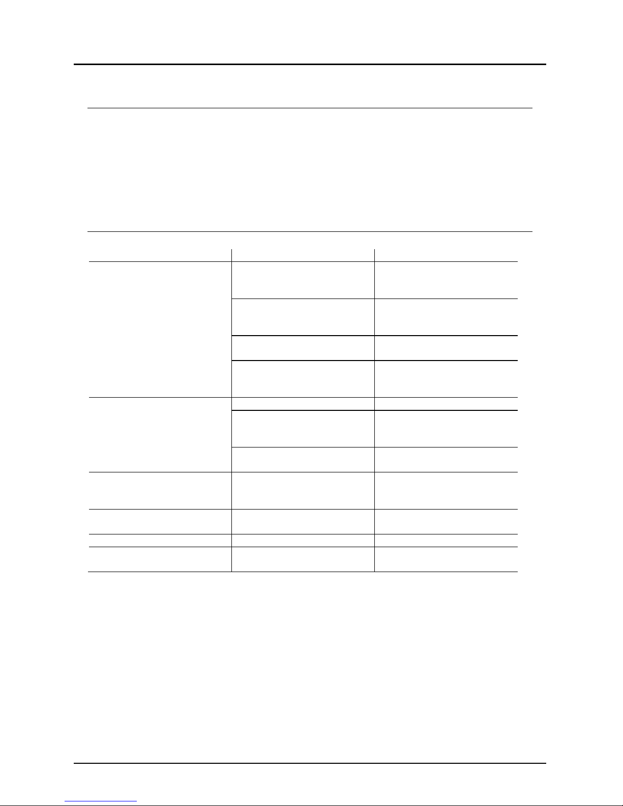
10.Technical Information
Model SEN-86x0 SEN -87x0
Technology internal diaphragm
Pressure type gauge pressure
Housing stainless steel 1.4305
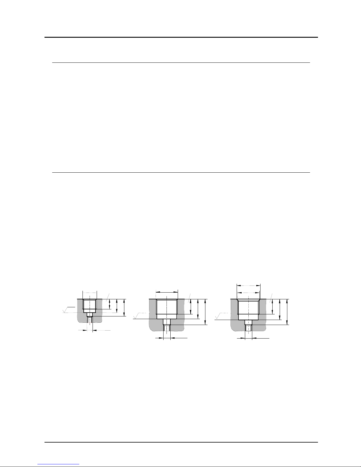
Connection: G ½ male; stainless steel
1.4301 (NPT, UNF on
request)
G ¼ male; stainless steel
1.4301 (NPT, UNF on
request)
Sensor element ceramic (Al2O3)
Measuring principle thick film techn. (DMS)
O-Ring NBR
Max. Temperature Storage: -30...+100 °C
Medium: -20...+125 °C
Ambient: -30...+100 °C
Storage: -30...+100 °C
Medium: -20...+ 85 °C
Ambient: -30...+100 °C
Pressure limitation < 60 bar: 2 x range
≥60 bar: 1.5 x range
Accuracy class 0.5 f.s.d.)
Repeatability ± 0.15 % (f.s.d.)
Characteristic deviation ± 0.3 % (f.s.d.)
Stability (annual) ± 0.2 % of full scale
in rated conditions
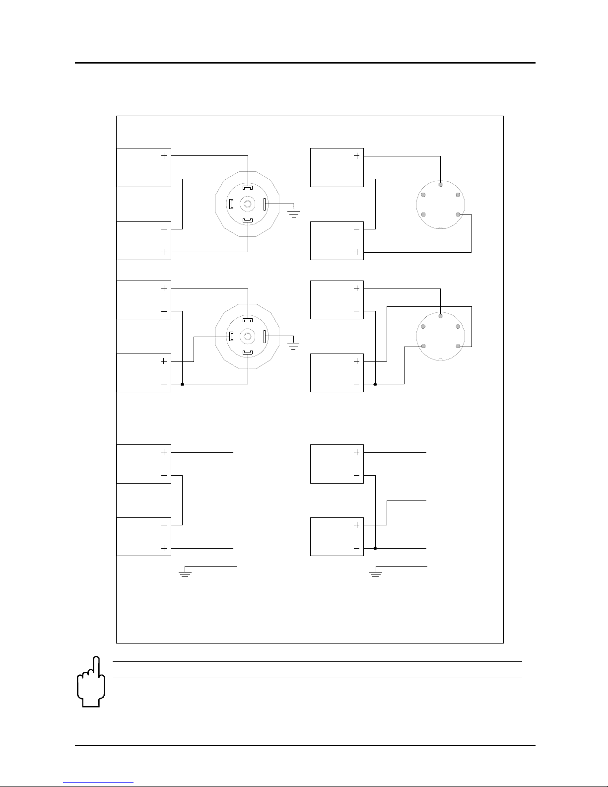
Electrical connection Plug DIN 43 650 A / Plug M12x1
Cable connection
Power supply 15...32 VDC
Output signal 4 – 20 mA, (2-wire), 0 – 10 VDC
Load () (UB– 15 V)/0.02 A (for 4 – 20 mA)
Response time 1 ms (within 10 – 90% of full scale)
Temp. comp. range -25...+85 °C
Temperature drift Zero:
± 0.02% full scale/K
Measuring span:
± 0.01% full scale/K
Protection IP 65 (SEN-860..; SEN-863..)
IP 68 (SEN-865..)
Options Absolute pressure for ranges 1.0...25 bar
Oil- and free of grease for oxygen
Silicone- and LABS free
Connection with 50 mm cooling fins tmax 125 °C
Connection and housing SS 1.45391) instead of 1.4305
Connection and housing SS 1.4571 instead of 1.4305
O-ring FPM instead of NBR
O ring PTFE (Kalrez) instead of NBR <100 bar
½” NPT thread instead of “G” G¼ DIN385-E inclusive seal
ring3)
Special connection2) on request
1) Seawater resistant
2) Please specify in writing
3) Adapter of PSD usable