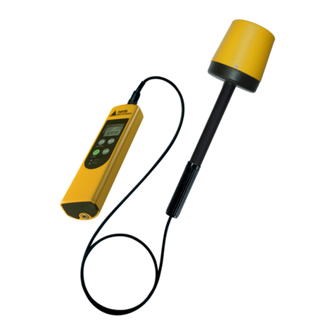
NARDA AMS-8063 Series User manual

NARDA
Safety
Test
Solutions
S.r.l. Socio Unico
Sales & Support:
Via Rimini, 22
20142 - Milano (MI)
Tel.: +39 02 581881
Fax: +39 02 58188273
Manufacturing Plant:
Via Benessea, 29/B
17035 - Cisano sul Neva (SV)
Tel.: +39 0182 58641
Fax: +39 0182 586400
SERIAL NUMBER OF THE INSTRUMENT
You can find the serial number on the side of the metal bracket located under the
baseplate, on the side of the Power pack and on the side of the Solar panels.
Serial number is in the form: 000XY00000.
The first three digits and the two letters are the Serial Number prefix, the last five
digits are the Serial Number suffix. The prefix is the same for identical instruments,
it changes only when a configuration change is made to the instrument.
The suffix is different for each instrument.
Document AMS8063EN-11107-1.23 – Copyright ©NARDA 2021
AMS-8063
AREA MONITOR SYSTEM
User’s Manual
AMS-8063/00
AMS-8063/01
AMS-8063/02

II Note and symbols
NOTE:
® Names and Logo are registered trademarks of Narda Safety Test Solutions GmbH – Trade names are
trademarks of the owners.
If the instrument is used in any other way than as described in this User’s Manual,
it may become unsafe.
Before using this product, the related documentation must be read with great care and fully understood to
familiarize with all the safety prescriptions.
To ensure the correct use and the maximum safety level, the User shall know all the instructions and
recommendations contained in this document.
This product is a Safety Class III instrument according to IEC classification
and has been designed to meet the requirements of EN61010-1 Safety
Requirements for Electrical Equipment for Measurement, Control and
Laboratory Use).
In accordance with the IEC classification, the power supply of this product meets requirements Safety Class II and
Installation Category II (having double insulation and able to carry out mono-phase power supply operations).
It complies with the requirements of Pollution Class II (usually only non-conductive pollution). However,
occasionally it may become temporarily conductive due to condense on it.
The information contained in this document is subject to change without notice.
EXPLANATION OF ELECTRICAL AND SAFETY SYMBOLS :
You now own a high-quality instrument that will give you many years of reliable service.
Nevertheless, even this product will eventually become obsolete. When that time comes, please
remember that electronic equipment must be disposed of in accordance with local regulations.
This product conforms to the WEEE Directive of the European Union (2002/96/EC) and belongs to
Category 9 (Monitoring and Control Instruments). You can return the instrument to us free of
charge for proper environment friendly disposal. You can obtain further information from your
local Narda Sales Partner or by visiting our website at www.narda-sts.it .
Warning, danger of electric shock
Earth
Read carefully the Operating Manual and its
instructions, pay attention to the safety symbols
Unit Earth Connection
Earth Protection
Equipotential
KEY TO THE SYMBOLS USED IN THIS DOCUMENT:
The DANGER sign draws attention to a serious risk to a person’s safety,
which, if not avoided, will result in death or serious injury. All the
precautions must be fully understood and applied before proceeding.
The WARNING sign indicates a hazardous situation, which, if not avoided,
could result in death or serious injury. All the precautions must be fully
understood and applied before proceeding.
The CAUTION sign indicates a hazardous situation, which, if not avoided,
could result in minor or moderate injury.
The NOTICE sign draws attention to a potential risk of damage to the
apparatus or loss of data.
The NOTE sign draws attention to important information.

Contents III
Contents
Page
Safety requirements and instructions…..........……........
EC Declaration of Conformity .........................................
VI
VII
1 General information Page
1.1 Documentation..............................................................
1.2 Introduction ……………....................…........................
1.3 Standard accessories ……………………………….......
1.3.1 Standard accessories AMS-8063-00…………..…….
1.3.2 Standard accessories AMS-8063-01…………..…….
1.3.3 Standard accessories AMS-8063-02…………..…….
1.4 Optional accessories…………………………………….
1.5 AMS-8063…………………………………………………
1.6 Main specifications……………………………………….
1.7 EHP-8063……………….….………………………..……
1.8 Support pole………………………………………………
1-1
1-1
1-2
1-2
1-3
1-4
1-5
1-6
1-7
1-9
1-10
2 Installation and use
Page
2.1 Introduction..................................................................
2.2 Initial inspection............................................................
2.3 Working environment...................................................
2.4 Return for repairs……..................................................
2.5 Cleaning………………..................................................
2.6 Installation and use.………………………………………
2.6.1 Installation of AMS-8063-00…………………..………
2.6.2 Installation of AMS-8063-01…………………..………
2.6.3 Installation of AMS-8063-02…………………..………
2.6.4 Supporto base, feet and pole …………….………..…
2.6.5 Solar panels (AMS-8063-00 and AMS-8063-01 only)
2.6.5.1 Solar panels mounting kit ………….……………….
2.6.5.2 Installation steps ……………………...……………..
2.6.5.3 Install the Solar panels to the Support base ……...
2.6.5.4 Solar panels wiring and fuse …………...………….
2.6.6 Battery pack wiring and fuse (AMS-8063-02 only)….
2.6.7 Baseplate mounting …………………………………...
2.6.8 Radome opening ………..…………………………..…
2.6.9 Battery pack power cable….………..………………...
2.6.10 10 Led LEDs 8063-Shutter status…………………..
2.6.11 Led WiFi converter status (AMS-8063-00 only)…..
2.6.12 Switch EHP-8063 on …….………….……………….
2.6.13 Led EHP-8063 status……………….………………..
2.6.14 AMS-8063-02 Interface box…………………………
2.6.15 Radome mounting………………….…………………
2.6.16 Bags ………….………………………………………..
2.6.17 Battery charging …….……………………………..…
2.6.18 External power supply.…….…………………………
2.7 AMS-8063-00 Operating principle ……….…………….
2.8 AMS-8063-01 Operating principle ……….…………….
2.9 AMS-8063-02 Operating principle ……….…………….
2-1
2-1
2-1
2-1
2-2
2-2
2-3
2-4
2-5
2-6
2-8
2-8
2-9
2-10
2-13
2-15
2-17
2-18
2-19
2-20
2-20
2-20
2-20
2-21
2-22
2-22
2-23
2-26
2-28
2-29
2-30

IV Contents
3 8063SW02 User’s guide Page
3.1 Introduction ………….........................................…......................
3.2 Hardware requirements …………………………………………….
3.3 Use of the Software 8063SW02…………….………....................
3.4 Software installation …….…………………………………….........
3.5 USB-RS232 Adapter (optional) or AMS-8063-02 Interface box..
3.6 Software 8063SW02 COM port settings ………………………….
3.7 AMS-8063 Delay command setting .....................…...................
3.8 AW5500 Access point installtion (AMS-8063-00 only)………….
3.9 STE02W Wifi Serial Converter installation (AMS-8063-00 only)
3.10 Starting the program ………………………….............................
3.11 Main window …………………………………………….………….
3.11.1 Tool bar……..…………………………………………………….
3.11.2 Setting menu …………………………………………………….
3.11.3 Option……………………………………………………………..
3.11.3.1 Aspect…………………………………………………………..
3.11.3.2 Sort by date…………………………………………………….
3.11.4 Settings……………………………………………………………
3.11.4.1 Frequency Table……………………………………………….
3.11.4.2 Measure…………………………………………………………
Table Mode……………………………………………………….………
AVG/RMS……………………………………………………….…...……
Spectrum Mode…………………………………………………………..
Preamplifier………………………………………………….……………
Trace……………………………………………………………….……...
Text file Separator…………………………………………….…………
Save Bitmap/jpg………….…………………………………….…….....
OK/Default/Cancel………………………………………………………
3.11.5 Station control panel……………………………………………
3.11.6 File………………………………………………………………..
3.11.6.1 Info………………………………………………………..........
3.11.6.2 Save Panel…………………………………………………….
3.11.6.3 Open Panels…………………………………………………..
3.11.7 SCAN……………………………………………………………..
3.11.8 EXECUTE………………………………………………………..
3.11.9 8063SW02 Operating principle………………………………..
3.12 Uninstalling Software ……………………………………………..
3.13 Uninstalling the driver of RS232-USB adapter (optional)……..
3-1
3-1
3-2
3-3
3-7
3-8
3-9
3-9
3-12
3-13
3-15
3-16
3-16
3-17
3-17
3-18
3-19
3-19
3-22
3-23
3-23
3-24
3-25
3-25
3-25
3-26
3-26
3-27
3-28
3-28
3-28
3-29
3-30
3-32
3-35
3-36
3-37
4 Data display Page
4.1 Introduction......…...............................…….................................
4.2 Calendar....................................................….............................
4.2.1 Data window..................................................…......................
4.3 Data display...............................................…..…..…..................
4.3.1 Main commands ….……………………………………………….
4.3.1.1 Open Scan………………………………………………………
Data folder….…………………………………………………………….
Structure of the .TXT file………………………………….…………….
Structure of the .JPG, .BMP and .PCM file…………………………..
Structure of the Table.mode.txt file……………………………………
Events folder………….………………………………………………….
4-1
4-1
4-1
4-4
4-4
4-4
4-4
4-6
4-7
4-8
4-9
5 AMS-8063/WMK Wall Mounting Kit
Page
5.1 Introduction ……………………………….……….…….................
5.2 Initial inspection……… ……….............................…...................
5.3. Working environment………………………………………………
5.4 Return for repair…………………………………………................
5.5. Cleaning……………………………………………………………..
5.6 Installation…………………………………………………………….
5-1
5-2
5-2
5-2
5-2
5-3
6 Packaging Instructions
Page
6.1 Introduction ……………………………….……….…….................
6.2 Packaging Instructions ……….............................…....................
6-1
6-1

Contents V
Figures
Figure
1-1
1-2
1-3
5-1
5-2
5-3
AMS-8063-00 or AMS-8063-01 Are Monitor System..…………
AMS-8063-02 receiver baseplate……..……………………….…
Panel of EHP-8063………….……………………………………..
AMS-8063/WMK Wall Mounting Kit……………………………...
AMS-8063/02 on AMS-8063/WMK……………………………….
AMS-8063-00 or AMS-8063-01 on AMS-8063/WMK ………….
Page
1-1
1-4
1-9
5-1
5-8
5-8
Tables
Table
Page
1-1
1-2
1-3
2-1
2-2
Technical Specifications of the AMS-8063…………………..….
General Specifications of the EHP-8063…………………..……
Technical Specifications of the EHP-8063……..……………….
Led 8063-Shutter………………….……………………………....
Led EHP-8063 status …………..……………………..……….…
1-7
1-8
1-10
2-20
2-20

VI Safety considerations
SAFETY RECOMMENDATIONS AND INSTRUCTIONS
This product has been designed, produced and tested in Italy, and it left the factory in conditions fully
complying with the current safety standards. To maintain it in safe conditions and ensure correct use,
these general instructions must be fully understood and applied before the product is used.
•When the device must be connected permanently, first provide effective grounding;
•If the device must be connected to other equipment or accessories, make sure they are all safely
grounded;
•In case of devices permanently connected to the power supply, and lacking any fuses or other
devices of mains protection, the power line must be equipped with adequate protection
commensurate to the consumption of all the devices connected to it;
•In case of connection of the device to the power mains, make sure before connection that the voltage
selected on the voltage switch and the fuses are adequate for the voltage of the actual mains;
•Devices in Safety Class I, equipped with connection to the power mains by means of cord and plug,
can only be plugged into a socket equipped with a ground wire;
•Any interruption or loosening of the ground wire or of a connecting power cable, inside or outside the
device, will cause a potential risk for the safety of the personnel;
•Ground connections must not be interrupted intentionally;
•To prevent the possible danger of electrocution, do not remove any covers, panels or guards installed
on the device, and refer only to NARDA Service Centers if maintenance should be necessary;
•To maintain adequate protection from fire hazards, replace fuses only with others of the same type
and rating;
•Follow the safety regulations and any additional instructions in this manual to prevent accidents and
damages.

EC Conformity VII
Dichiarazione di Conformità
EU Declaration of Conformity
In accordo alla Decisione 768/2008/EC, conforme alle direttive EMC 2014/30/UE, Bassa Tensione 2014/35/UE e
RoHS 2011/65/UE, ed anche alle norme ISO/IEC 17050-1 e 17050-2.
In accordance with the Decision 768/2008/EC, compliant to the Directives EMC 2014/30/EU, Low Voltage 2014/35/EU and
RoHS 2011/65/EU, also compliant to the ISO/IEC standard 17050-1 and 17050-2
Il costruttore
The manufacturer
narda Safety Test Solutions S.r.l. Socio Unico
Indirizzo
Address
Via Benessea, 29 / B
I-17035 Cisano sul Neva (SV) - Italy
sulla base delle seguenti norme europee armonizzate, applicate con esito positivo:
based on the following harmonized European Standards, successfully applied:
EMC - Emissioni:
EMC - Emission:
EN 61326-1 (2013)
EMC - Immunità:
EMC - Immunity:
EN 61326-1 (2013)
Sicurezza:
Safety:
EN 61010-1 (2010)
dichiara, sotto la propria responsabilità, che il prodotto:
declares, under its sole responsibility, that the product:
Descrizione
Description
SISTEMA DI MONITORAGGIO SELETTIVO
AREA MONITOR SYSTEM
Modello
Model
AMS-8063 /00 /01 /02
è conforme ai requisiti essenziali delle seguenti Direttive:
conforms with the essential requirements of the following Directives:
Bassa Tensione
Low Voltage
2014/35/EU
Compatibiltà Elettromagnetica
EMC
2014/30/EU
RoHS
RoHS
2011/65/EU
Cisano sul Neva, 30 June 2017
Egon Stocca
General Manager

VIII Safety considerations
This page has been intentionally left blank

General Information 1-1
1 – General Information
1.1 Documentation
This Users Manual contains the following annexes:
•A form to be returned to NARDA with the device when requesting
service.
•A checklist of the accessories included in the shipment.
1.2 Introduction
The AMS-8063 family products are revolutionary, accurate and reliable
solutions for remote and continuous monitoring of electromagnetic fields.
The AMS-8063 Area Monitor consist of a protective case made of material
that is transparent to electromagnetic fields and designed to house the
EHP-8063 E-H fields analyzer and the data transmission devices.
EHP-8063 has been designed for 3 axis accurate measurements of both
electric and magnetic fields, in the frequency range 9 kHz to 30 MHz.
The Wi-Fi Serial Converter (AMS-8063-00) allow the connection of the
system to a WLAN network with TCP/IP protocol.
The AMS-8063-01 can only be connected to the PC by RS232 cable.
The PC handles the AMS-8063-02 through the AMS-8063-02 Interface box
that allows a long optical connection
The AMS-8063-00 e AMS-8063-01 models are powered by high capacity
back-up batteries and solar panels (twin pair).
AMS-8063-02 does not have any solar cells, as it is powered by high
capacity rechargeable batteries.
An external power supply is provided for continuous, indoor operation for all
models.
The system of acquisition makes it possible to program each parameter
and transfer to a PC the data saved into the unit. The recorded data can be
viewed either as a graph or as a table.
Fig. 1-1 AMS-8063-00 or AMS-8063-01 Area Monitor System
Document AMS8063EN-11107-1.23 - © NARDA 2021

1-2 General Information
1.3 Standard accessories
1.3.1
Standard accessories
AMS-8063-00
Standard accessories included with the AMS-8063-00 are:
The baseplate includes:
•EHP-8063 Field Analyzer;
•EHP-8063 power supply cable
•8063-Shutter
•Wi-Fi Serial Converter;
•Rx/Tx cable;
•FO-8053/1 optical fiber (1m);
•Air filter
•Radome with 4pcs. Torx screws M5x16mm and 4 pcs. plastic washer;
Other accessories:
•Solar panels;
•Battery Pack;
•Fuse
•AC/DC Converter with plug adapters;
•Operating Manual;
•Certificate of Compliance;
•Return for Repair Form;
•Software Media;
•Torx Allen Key;
•Reversible screwdriver
•13mm Combination Wrench
•7mm Combination Wrench
•Mast;
•Weight bags;
•Mounting kit.

General Information 1-3
1.3.2 Standard accessories
AMS-8063-01
Standard accessories included with the AMS-8063-01 are:
The baseplate includes:
•EHP-8063 Field Analyzer;
•EHP-8063 power supply cable;
•8063-Shutter
•RS232 cable;
•USB-RS232 serial converter;
•Rx/Tx cable;
•FO-8053/1 optical fiber (1m);
•Air filter
•Radome with 4pcs. Torx screws M5x16mm and 4 pcs. plastic washer;
Other accessories:
•Solar panels;
•Battery Pack;
•Fuse
•AC/DC Converter with plug adapters;
•Operating Manual;
•Certificate of Compliance;
•Return for Repair Form;
•Software Media;
•Torx Allen Key;
•Reversible screwdriver
•13mm Combination Wrench
•7mm Combination Wrench
•Mast;
•Weight bags;
•Mounting kit.

1-4 General Information
1.3.3 Standard accessories
AMS-8063-02
Standard accessories included with the AMS-8063-02 are:
The baseplate includes:
•EHP-8063 Field Analyzer;
•EHP-8063 power supply cable;
•8063-Shutter
•Optical / Serial Converter;
•Rx/Tx cable
•FO-8053/1 optical fiber (1m);
•FO-8063/02 external long link fiber optic cable (5m) for service
•Air filter
•Radome with 4pcs. Torx screws M5x16mm and 4 pcs. plastic washer;
Other accessories:
•Battery Pack;
•Fuse;
•AC/DC Converter with plug adapters;
•Operating Manual;
•Certificate of Compliance;
•Return for Repair Form;
•Software Media;
•Torx Allen Key;
•Reversible screwdriver
•13mm Combination Wrench
•Mast;
•Weight bags;
•Mounting kit.
Fig. 1-2 AMS-8063-02 receiver baseplate

General Information 1-5
1.4 Optional accessories
Accessories supplied separately (on charge) for all models:
•AMS-8063/WMK Wall Mounting Kit;

1-6 General Information
1.5 AMS-8063 The AMS-8063 Area Monitor System includes:
1) EHP-8063 Field Analyzer;
2) EHP-8063 plexiglass bracket;
3) EHP-8063 support pole;
4) Baseplate with data transmission and power supply devices; it is shown
AMS-8063-02 in the figure below;
5) Solar panels (AMS-8063-00 and AMS-8063-01 only);
6) Battery pack and support base.

General Information 1-7
1.6 Main Specifications Tables 1-1 – 1-2 list the specifications of all models.
Table 1-1 - Technical Specifications of the AMS-8063
Measuring range
Frequency range 9 kHz - 30 MHz
Measurement range 0.1 - 1000 V/m (from 9 kHz to 30 MHz)
0.03 - 300 A/m (from 9 kHz to 3 MHz)
0.003 - 30 A/m (from 300 kHz to 30 MHz)
Resolution 0.01 V/m, 0.1 mA/m
Sensitivity 0.01 V/m (depending on the RBW filter)
Measurement units (through software PC) V/m, A/m
Measured field Electric and magnetic
Measurement/acquisition functions
Storing interval Table mode: selectable from 1 to 1440 minutes
Spectrum mode selectable 10, 15, 30 minutes or
1, 2, 3, 4, 5, 6, 12, 24 Hours or exceeding threshold setting
Functions Spectrum Mode; Frequency Table, AVG, RMS
LOG file All operations are written in a LOG file
Zoom Horizontal
Firmware upgrade Remote by PC
Software upgrade free, download from NARDA Web site: www.narda-sts.it

1-8 General Information
TABLE 1-2 General Specifications of the AMS-8063
Communication Wireless LAN 802.11b 2.4 GHz (AMS-8063-00)
RS 232 (AMS-8063-01)
Optical Fiber converter / RS232 (AMS-8063-02)
Battery pack Backup sealed Pb rechargeable battery, 12 V 32 Ah
Solar panels 2x40W 17.5V (AMS-8063-00 and AMS-8063-01 only)
Consumption 4W
External power supply 100…240 V, 50/60 Hz to 24 VDC, 1.25A
Autonomy with batteries only > 48 Hours
Autonomy with Solar panel 24 Hours / 365 days for PSH ≥2
Recharge time > 12 Hours with external power supply
Operating temperature -20 °C to +55 °C
Dimensions Radome (ØxH) 250x740 mm
Pole (ØxH) 60x760 mm
Base (LxPxH) 660x600x95 mm
Battery pack (LxPxH) 310x240x190 mm
Solar panels (LxPxH) 930x35x665 mm
Weight
AMS-8063-00 3,5 kg only the unit;
35.0 kg total weight inclusive of supports and base
AMS-8063-01 3,0 kg only the unit;
35.0 kg total weight inclusive of supports and base
AMS-8063-02 3,5 kg only the unit;
26.5 kg total weight inclusive of supports and base
Protection grade IP54

General Information 1-9
1.7 EHP-8063 EHP-8063 is housed in a small cubic housing; the bottom side panel
includes an optic fiber connector, ON/OFF level switch and operation LED.
EHP-8063 is managed internally with a microprocessor that controls all the
main functions.
Electric or Magnetic field is picked up by three sensors on the X, Y and Z
orthogonal axes. A Digital/Analog conversion follows which transforms the
signal into numeric information processed by a Digital Signal Processing
unit.
The magnetic sensor system is composed by three magnetic loops
positioned orthogonal each other. The electric sensor system is composed
by three orthogonal parallel capacitors installed on opposite side of the
magnetic loops.
EHP-8063 has an internal rechargeable Ni-Mh battery that can be
recharged with the battery pack.
Fig. 1-3 Panel of EHP-8063
Key:
DATA: Led
POWER ON: switches EHP-8063 on/off
OPTIC LINK: Fiber optic connector
CHARGER: Not available
AUX: Not available
Correct readings may be conditioned by the nature of the places in
which the field monitoring system is installed.
The field sensor is affected by huge metallic masses or other objects
that may reflect the signal, if located in the vicinity of the unit.
Whenever possible, it is a good rule to install the unit at some
distance from walls, high voltage pylons, buildings and other
obstacles that could affect the signals reaching the sensor.
EHP-8063 is automatically detected by the control system integrated
in the AMS-8063, so it is not necessary to perform any operation.
Do not expose the EHP-8063 to a field higher than the max. allowed.
Field strengths exceeding the allowed may cause severe probe
damage whether it is connected or not, either turner ON or OFF.
When opening the protective case of the monitoring station, to avoid
damages, remove along its axis the protective case from probe.
The minimum voltage level for operation is 3V. Under this battery
voltage the analyzer will turn OFF automatically and the battery will be
charged.

1-10 General Information
Table 1-3 Technical specifications of the EHP-8063 Electric and Magnetic Field Analyzer
Electric Field Magnetic Field
Mode A
Magnetic Field
Mode B
Frequency range
9 kHz ÷ 30 MHz 9 kHz ÷ 3 MHz 300 kHz ÷ 30 MHz
Measurement range @10kHz RBW
with preamplifier ON
0,1 ÷ 1000 V/m
0,02 ÷ 200 V/m
30 mA/m ÷ 300 A/m
6 mA/m ÷ 60 A/m
3 mA/m ÷ 30 A/m
0.6 mA/m ÷ 6 A/m
Dynamic range
> 80 dB
Resolution
0.01 V/m 1 mA/m 0.1 mA/m
Sensitivity @10kHz RBW (*)
with preamplifier ON
0.1 V/m
0.02 V/m
30 mA/m
6 mA/m
3 mA/m
0.6 mA/m
Flatness
0,5 dB
100 kHz – 27 MHz
@ 20 V/m
0,8 dB
150 kHz – 3 MHz
@ 166 mA/m
0,8 dB
300 kHz – 27 MHz
@ 53 mA/m
Anisotropicity @1MHz 0.8 dB
Linearity @1MHz 0,5 dB from FS to –60 dBFS
SPAN 9 kHz to FULL SPAN
RBW 1 kHz – 3 kHz – 10 kHz – 30 kHz – 100 kHz – 300 kHz
Rejection to E fields
--- > 20 dB
Rejection to H fields
> 20 dB ---
Calibration internal E
2
PROM
Temperature error 0,02 dB/°C
Dimensions 92 x 92 x 109 mm
Weight 550 g
Preamplifier selectable ON/OFF, 14dB
Units V/m, A/m
Internal battery 1,2 V x 3 Ni-Mh, rechargeable
Firmware updating through PC connection
Self-test automatic at power on
Operating temperature -20 to +55°C
Storage temperature -20 to +70°C
(*) The maximum sensitivity is achieved with the filter to 10 kHz
1.8 Support pole
The supplied support pole is used to position the EHP-8063 field analyzer
far from the data transmission/power supply devices and the operator
avoiding any alteration of the field to be monitored.
The support pole is fixed to the baseplate and to the EHP-8063 plexiglass
bracket.
The support pole has been specifically designed to prevent
influencing the field measurements.

Installation and use 2-1
2 - Installation and use
2.1 Introduction
This section provides the information necessary to install and use the AMS-
8063 Area Monitoring System.
It also includes information regarding initial inspection, power requirements,
interconnections, working environment, assembly, cleaning, storage and
shipment.
2.2 Initial inspection
Inspect the package for any possible damage
If the packaging or protective material are damaged, check that the
content is complete and that the instrument has not been damaged in
any of its electrical or mechanical parts. Check the accessories,
referring to the checklist enclosed with the manual. Report any
noticed damage to the forwarder and to NARDA.
2.3 Working environment
The working conditions for the instrument are as follows:
•Temperature
•Relative humidity
From -20°C to +50°C
< 95%
The instrument should be stored in a clean, dry place free of acids, dust
and moisture
The storage environment must have the following specifications
•Temperature
•Relative humidity
•Altitude
From -20°C to + 70°C
< 99%
Up to 4000 m (a.s.l.)
2.4 Return for repairs Any part of the instrument, including the batteries, can only be replaced by
NARDA, therefore, in case of damage to parts and/or malfunctions, contact
the NARDA service center.
When the instrument has to be returned to NARDA for repairs, please
complete the form included in this User’s Manual, filling in all the
information necessary for the service requested.
To reduce the time necessary for the repair, be as specific as possible in
describing the malfunction. If the problem only occurs under specific
conditions, detail in the best possible way how to reproduce these
conditions.
Whenever possible, it is preferable to use the original packing for return,
making sure to wrap the device in heavy paper or plastic (see section 6 for
detailed packaging instructions). In alternative, pack the equipment in a
sturdy cardbox with plenty of impact absorbing material all around the
equipment, to ensure a tight fit and prevent it from moving inside the box.
Take special precautions to protect the solar cells and GSM modem
antenna. Seal the package securely and write FRAGILE on the outside to
encourage careful handling.
1
Document AMS8063EN-11107-1.23 - © NARDA 2021

2-2 Installation and use
2.5 Cleaning
Use a clean, soft, dry cloth to clean the instrument and the solar cells.
It is suggested to replace air filter at least once a year or more
frequently if needed.
To clean the instrument do not use solvents, acids, cleaning fluid,
turpentine, acetone or similar products which could damage it.
2.6 Installation and use
The AMS-8063 Area Monitor consist of a protective case made of material
that is transparent to electromagnetic fields and designed to house the
EHP-8063 E-H fields analyzer and the data transmission/power supply
devices.
The AMS-8063-00 e AMS-8063-01 models are powered by high
capacity back-up batteries and solar panels (twin pair).
Model AMS8063-02 don’t have the solar panel module.
This manual suits for next models
7
Table of contents
Other NARDA Measuring Instrument manuals

NARDA
NARDA L3HARRIS SMARTS II User manual

NARDA
NARDA 8718 User manual

NARDA
NARDA AMS-8061 User manual

NARDA
NARDA ESM-10 RadMan Mobile User manual

NARDA
NARDA EHP-50-G User manual

NARDA
NARDA SRM-3006 User manual

NARDA
NARDA AMB-8059 User manual

NARDA
NARDA 8718B User manual

NARDA
NARDA NBM-550 User manual

NARDA
NARDA PMM PL-01 User manual
Popular Measuring Instrument manuals by other brands

PCB Piezotronics
PCB Piezotronics W356A61/NC Installation and operating manual

PR electronics
PR electronics PReview 5515 manual

Hilti
Hilti PRI 36 operating instructions

MetLogix
MetLogix Mx200 user guide

Anaheim Scientific
Anaheim Scientific H400 instruction manual

ABLE
ABLE BEKA BA504E Installation & maintenance instructions