Koehler KV4000 Guide

operation and instruction manual
K23702, K23708, K23792, K23798,
K23802, K23892
Kinematic Viscosity Bath, KV4000 & HKV4000
service | innovation | technology
REV K-A

KV4000 & HKV4000 Kinematic Viscosity Bath
Operation and Instruction Manual
- ii -

KV4000 & HKV4000 Kinematic Viscosity Bath
Operation and Instruction Manual
- iii -
CERTIFICATE OF CONFORMANCE
Constant Temperature Kinematic Viscosity Bath, KV4000 & HKV4000
K23702, K23708, K23792, K23798, K23802, K23892
This certificate verifies that part numbers K23702, K23708, K23792, K23798, K23802, K23892, Constant Temperature
Kinematic Viscosity Baths, were manufactured in conformance with the applicable standards set forth in this
certification.
Specifications: ASTM D445
ASTM D2170
ASTM D6074
ASTM D6158
IP 71
ISO 3104
DIN 51550
FTM 791-305
NF T 60-100
This unit is tested before it leaves the factory, to ensure total functionality and compliance to the above specifications
and ASTM standards. Test and inspection records are on file for verification.
Vincent Colantuoni
Product Manager
Koehler Instrument Company, Inc.
1595 Sycamore Ave.
Bohemia, NY 11716
United States of America
Serial Number: ________________________
Date: ________________________________

KV4000 & HKV4000 Kinematic Viscosity Bath
Operation and Instruction Manual
- iv -

KV4000 & HKV4000 Kinematic Viscosity Bath
Operation and Instruction Manual
- v -
WEEE Directive
Background
The goal of the WEEE Directive is to encourage design of environment-friendly products that increase reuse, recycling and other forms
of recovery to reduce waste streams and applies to listed Electronic and Electrical Equipment (EEE) and Koehler's equipment falls broadly
into Appendix 1A; Section 9 Monitoring and Control Equipment: Measuring, weighing or adjusting appliances for household or as
laboratory equipment.
Any associated non-embedded equipment such as Lighting (Saybolt Color) and PCs/Printers also fall under WEEE. If provided with an
order these ancillary items must be WEEE compliant. For these and other reasons (printer cartridges are regionalized) the equipment
must be supplied through a third party supplier in Europe.
The WEEE Directive applies to electrical and electronic equipment falling under the categories set out in Annex IA provided that the
equipment concerned is not part of another type of equipment that does not fall within the scope of this Directive. Annex IB contains a list
of products which fall under the categories set out in Annex IA.
http://eur-lex.europa.eu/LexUriServ/LexUriServ.do?uri=OJ:L:2003:037:0024:0038:en:PDF
We do not qualify for any of the 10 exemption categories.
http://www.dpa-system.dk/en/WEEE/Products/Exemptions
Professional use
For equipment defined for ’professional use’ local authorities have no role to play. Producers and importers are basically responsible for
collection of WEEE recyclables from the professional user and for subsequent management. A separate statement is given cataloging
the items that require separation from the equipment along with basic information on subsequent processing or recycling prior to disposal
of the equipment.
http://www.dpa-system.dk/en/WEEE/Products/Private-or-professional-use
Responsibility for Registration and Annual Reporting:
Koehler will not sell directly to end users in the EU and so has no responsibility to register within each EU state and to make annual
reports. Koehler declares that this responsibility is born by the importer who is the first level of the distribution chain and is subject to
producer responsibility. We will communicate this in writing to our distributor/importers in the EU stating they are responsible to satisfy
WEEE registration and reporting requirements in the EU states where they conduct sales activities.
It is illegal to market electrical and electronic equipment covered by producer responsibility without being registered.
http://www.dpa-system.dk/en/WEEE/Producers/Whoissubjecttoproducerresponsibility
Product Design
Koehler's designs allow for complete disassembly to a modular level which usually allows for standard recycling. A qualified refrigeration
system technician must be consulted when disassembling and de-commissioning any equipment with refrigeration systems.
Koehler's scientific testing equipment is robustly designed to function over a long service life and are typically repaired many times over
the course of years rather than being replaced. We believe that re-use and refurbishment is the very best form of re-cycling.
All batteries must be readily removable not soldered in place.

KV4000 & HKV4000 Kinematic Viscosity Bath
Operation and Instruction Manual
- vi -
Recycling instructions
In the event that replacement becomes necessary, we will include instructions, particularized to each instrument that informs the customer
of their recycling responsibilities and giving them guidance in doing this. All Koehler equipment has been placed on the market since 13th
August 2005 and so Koehler is defined as a "new WEEE producer". As such we must provide information on refurbishment, treatment,
and re-use.
Our instrument manual will include this compliance statement and indicate that any collection of materials will be handled by their
authorized distributor. In the event that the distributor is unreachable or is no longer a distributor for Koehler Instrument, Co., other
arrangements may be made including accepting the materials directly.
Recycling is free of charge. Shipping is the responsibility of the end users. Whether shipping to a distributor or to Koehler directly, safe,
properly declared, and labeled packaging and shipping expenses are the sole responsibility of the end user.
WEEE Marking
Since Koehler products are subject to the WEEE Directive we must display the WEEE symbol shown above in accordance with European
Standard EN 50419 on the equipment. It must be indelible, at least 5mm in height, and clearly legible. If the equipment is too small the
mark must be in the product literature, guarantee certificate, or on the packaging. Rules on marking are established in section 49 of the
WEEE Order.
Koehler Instrument Company, Inc.
c/o RECYCLING
1595 Sycamore, Ave.
Bohemia, NY 11716
As a minimum the following substances, preparations and components have to be removed from any separately collected WEEE:
- Mercury containing components, such as switches or backlighting lamps (compact fluorescent lamps, CFL),
- Batteries
- Printed circuit boards if the surface of the printed circuit board is greater than 10 square centimeters (about 4 sq in.),
- Toner cartridges, liquid and pasty, as well as color toner,
- Chlorofluorocarbons (CFC), hydrochlorofluorocarbons (HCFC) or hydrofluorocarbons (HFC), hydrocarbons (HC)
- Liquid crystal displays (together with their casing where appropriate) of a surface greater than 100 square centimeters and all those
back-lighted with gas discharge lamps,
- External electric cables
- Components containing refractory ceramic fibers as described in Commission Directive 97/69/EC of 5 December 1997 adapting to
technical progress Council Directive 67/548/EEC relating to the classification, packaging and labeling of dangerous substances (2),
- Electrolyte capacitors containing substances of concern (height > 25 mm, diameter > 25 mm or proportionately similar volume)
2. The following components of WEEE that is separately collected have to be treated as indicated:
- Equipment containing gases that are ozone depleting or have a global warming potential (GWP) above 15, such as those contained in
foams and refrigeration circuits: the gases must be properly extracted and properly treated. Ozone-depleting gases must be treated in
accordance with Regulation (EC) No 2037/2000 of the European Parliament and of the Council of 29 June 2000 on substances that
deplete the ozone layer (4).

KV4000 & HKV4000 Kinematic Viscosity Bath
Operation and Instruction Manual
- vii -
Table of Contents
1. Introduction 2
1.1. Koehler’s Commitment to Our Customers 2
1.2. Recommended Resources and Publications 2
1.3. Instrument Specifications 3
2. Safety Information and Warnings 3
3. Getting Started 3
3.1. Packing List 4
3.2.Unpacking 4
3.3.Setup 5
4. Descriptions 6
4.1.Instrument Description 6
4.2.Accessories for Running Tests 7
4.3.Temperature Controller 9
5. Operation 10
5.1.Bath 10
5.2.Start Up 11
5.3.Control Panel Operation 11
5.4.Test Procedure 13
6. Safety Features 14
6.1.Over-Temperature Protection 14
6.2. Over-Power Protection 15
7. Maintenance 15
7.1.Routine Maintenance 15
7.2.Bath Cleaning 15
7.3.Draining / Changing Bath Medium 16
7.4.Changing Bath Lamp / Bulb 17
7.5.Replacement Parts 17
8. Wiring Diagram 18
9. Troubleshooting 23
9.1.Unit does not power-up 23
9.2.Unit is on and keeps resetting into start up routine 23
9.3.Unit is on but bath does not heat up 23
9.4.Bath heats up but temperature does not stabilize 23
10. Service 23
11. Storage 23
12. Warranty 24
13. Returned Goods Policy 24

KV4000 & HKV4000 Kinematic Viscosity Bath
Operation and Instruction Manual
- 2 -
1. Introduction
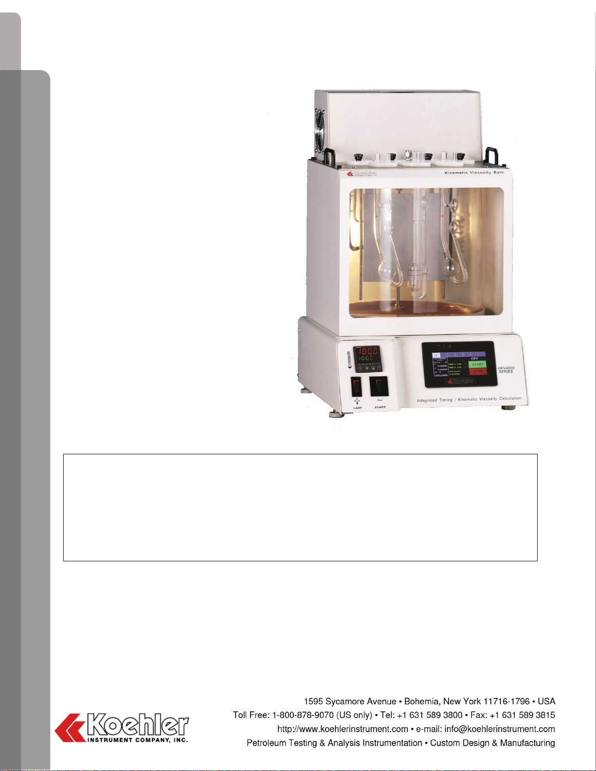
The Koehler KV4000 Kinematic Viscosity Instrument & HKV4000 High Temperature Kinematic Viscosity Instrument are the latest
designs for performing kinematic viscosity tests with glass capillary viscometers according to the ASTM D445 test method and
related test specifications.
This manual provides important information regarding safety, technical reference, installation requirements, operating condition
specifications, user facility resource requirements, and operating instructions for the Kinematic Viscosity Instrument and Data
Acquisition Software. This manual should also be used in conjunction with applicable published laboratory procedures. Information
on these procedures is given in section 1.2.
1.1. Koehler’s Commitment to Our Customers
Providing quality testing instrumentation and technical support services for research and testing laboratories has been our
specialty for almost 100 years. At Koehler, the primary focus of our business is providing you with the full support of your laboratory
testing needs. Our products are backed by our staff of technically knowledgeable, trained specialists who are experienced in both
petroleum products testing and instrument service to better understand your requirements and provide you with the best solutions.
You can depend on Koehler for a full range of accurate and reliable instrumentation as well as support for your laboratory testing
programs. Please do not hesitate to contact us at any time with your inquiries about equipment, tests, or technical support.
Toll Free: 1-800-878-9070 (US only)
Tel: +1 631 589 3800
Fax: +1 631 589 3815
Email: [email protected]om
http://www.koehlerinstrument.com
1.2. Recommended Resources and Publications
1.American Society for Testing and Materials (ASTM)
100 Barr Harbor Drive West Conshohocken, Pennsylvania
19428- 2959, USA
Tel: +1 610 832 9500
Fax: +1 610 832 9555
http://www.astm.org
ASTM Publication:
•ASTM D445: Kinematic Viscosity of Transparent and
Opaque Liquids (and the Calculation of Dynamic
Viscosity)
•ASTM D2170: Kinematic Viscosity of Asphalts
(Bitumens)
•ASTM D6074: Standard Guide for Characterizing
Hydrocarbon Lubricant Base Oils
•ASTM D6158: Standard Specification for Mineral
Hydraulic Oils
2. International Organization for Standardization (ISO)
1, rue de Varembé
Case postale 56
CH-1211 Geneva 20, Switzerland
Tel: 41 22 749 01 11
Fax: 41 22 733 34 30
http://www.iso.org
ISO Publication:
•ISO 3104: Petroleum products - Transparent and
Opaque Liquids - Determination of Kinematic
Viscosity and Calculation of Dynamic Viscosity
3. Energy Institute (IP)
61 New Cavendish Street
London, WIM 8AR, United Kingdom
Tel: 44 (0)20 7467 7100
Fax: 44 (0)20 7255 1472
http://www.energyinstpubs.org.uk/
IP Publication:
•IP 71: Kinematic Viscosity and Calculation of
Dynamic Viscosity
•IP 319: Kinematic viscosity of bitumens
4. Deutsche International Norm (DIN)
http://www.din.de
DIN Publication:
•DIN 51550: Determination of Kinematic Viscosity and
Dynamic Viscosity
5. Federal Test Method (FTM)
FTM Publication:
•FTM 791-305: Kinematic Viscosity of Petroleum
Products
6. Association Francaise de Normalisation (ANFOR)
http://www.anfor.fr
ANFOR Publication:
•NFT 60-100: Kinematic Viscosity of Petroleum
Products

KV4000 & HKV4000 Kinematic Viscosity Bath
Operation and Instruction Manual
- 3 -
1.3. Instrument Specifications
*Temperatures below ambient require an optional external chiller.
2. Safety Information and Warnings
Safety Considerations. The use of this equipment may involve hazardous materials and operations. This manual does not purport
to address all of the safety problems associated with the use of this equipment. It is the responsibility of any user of this equipment
to investigate, research, and establish appropriate safety and health practices and determine the applicability of regulatory
limitations prior to use.
Equipment Modifications and Replacement Parts. Any modification or alteration of this equipment from that of factory
specifications is NOT recommended because it voids the manufacturer warranty, product safety, performance specifications,
and/or certifications whether specified or implied, and may result in personal injury and/or property loss. Replacement parts must
be O.E.M. exact replacement equipment.
Unit Design. This equipment is specifically designed for use in accordance with the applicable standard test methods listed in
section 1.2 of this manual. The use of this equipment in accordance with any other test procedures, or for any other purpose, is
not recommended and may be extremely hazardous.
Over Temperature Protection. This unit is equipped with Over Temperature Protection (OTP) circuitry to prevent overheating.
The unit will automatically interrupt power whether equipment malfunction or operator error causes the temperature to exceed
either 20 °C above the set point or the maximum recommended temperature range. The power can only then be restored by
identifying and correcting the problem, Allowing the unit to return to normal operating temperatures, and resetting the power to the
unit.
Chemical Reagents Information. Chemicals and reagents used in performing the test may exhibit potential hazards. Any user
must be familiarized with the possible dangers before use. We also recommend consulting the Material Data and Safety Sheet
(MSDS) on each chemical reagent for additional information. MSDS information can be easily located on the internet at
http://siri.uvm.edu or http://www.sigma-aldrich.com.
3. Getting Started
The instructions for preparing the equipment assume that the user is aware of the contents of this document, which lists the
warranty conditions and important precautions.
Models:
K23702
Standard (KV)
12” Bath
115V 60Hz 12.6A
K23792
Standard (KV)
12” Bath
220-240V 50/60Hz 7.2A
K23708
Standard (KV)
18” Bath
115V 60Hz 12.6A
K23798
Standard (KV)
18” Bath
220-240V 50/60Hz 7.2A
K23802
High Temp (HKV)
12”Bath
115V 60Hz 12.7A
K23892
High Temp (HKV)
12”Bath
220-240V 50/60Hz 7.3A
Temperature Range:
Ambient to 150°C (302°F) for KV models
Ambient to 232°C (450°F) for HKV models
Optional Temperature Range*:
-20° to 150°C (-4° to 302°F) for KV models
10° to 150°C (50° to 302°F) for HKV models
Temperature Control Stability:
Exceeds ASTM Requirements
Viscometer Ports:
Seven (7) Round 2” (51mm) ports
Capacity:
Seven (7) Glass Capillary Viscometers
Bath Medium:
Water or suitable head transfer fluid
Bath Medium Capacity:
22L (5.8 gal) for 12”Baths
34 L (8.9 gal) for 18”Baths

KV4000 & HKV4000 Kinematic Viscosity Bath
Operation and Instruction Manual
- 4 -
3.1. Packing List
•KV4000 Kinematic Viscosity Bath or HKV4000 High Temperature Kinematic Viscosity Bath
•Seven (7) Viscometer Port Covers
•KV4000/HKV4000-Manual KV4000 & HKV4000 Operation and Instruction Manual
3.2. Unpacking
1. Check Shock Watch Label on Cardboard Box for indication of rough handling and possible damage.
2. Check labeling for correct orientation of instrument. (e.g. This Side Up)
3. Carefully open top of box with box cutter and remove packing foam.
4. Look inside bath from top of box, to verify that the Glass Bath Jar is in tact.
5. Make two additional vertical cuts, using box cutter, along length of two sides of the box and remove packing foam.
6. Extract instrument and place on suitable cart for transportation to work area / lab bench.
WARNING: Be sure two or more individuals are available for extracting and lifting instrument from box to cart and from cart
to bench. Individuals must lift in accordance to proper technique. See Figure below.
7. Lift instrument from cart and place on bench.
8. Remove foam insert Borosilicate Glass Jar as per steps 9 thru 19.
9. Using a flat head screwdriver, remove the four (4) silver screws located at the four corners of the back panel.
10. Remove the back panel plate and set aside.
11. A collection of wires runs from the lower control panel up the left side, while looking at the back of the bath. Halfway up the
wiring are three points where the wires can be disconnected. See Figure below:
12. There are a total of three joints to disconnect. First disconnect the single large cluster of wires by pressing in the sides of the
lower plastic piece then pulling the top plastic piece.
13. Then disconnect the two smaller joints. Each side of the joint is labeled with an identical number one (1) or number two (2).
This makes for easy connection when re-assembling the instrument.

KV4000 & HKV4000 Kinematic Viscosity Bath
Operation and Instruction Manual
- 5 -
14. Once the wiring is completely disassembled it is safe to remove the top assembly of the bath.
15. Remove the six (6) screws lining the two sides of the top assembly with a Philips head screw driver.
16. Make sure there is sufficient space with cleaning clothes to place the top assembly when lifted off the bath.
17. Lift the top assembly with one hand on the back side and one hand on the front side of the top assembly. Place top plate
assembly on flat surface with the back side of the top plate assembly and the heating coils on the surface.
18. With the top plate assembly now removed from the main instrument it is now easy to access the bath jar to remove the
protective foam insert.
19. Re-assemble the instrument
20. Ensure that all parts listed on the packing list are present. Inspect the unit and all accessories for damage. If any damage is
found, keep all packing materials and immediately report the damage to the carrier. We will assist you with your claim, if
requested. When submitting a claim for shipping damage, request that the carrier inspect the shipping container and
equipment. Do not return goods to Koehler without written authorization.
3.3. Setup
Equipment Placement: Make sure the instrument in placed on a firm, level table in an area with adequate ventilation or in a hood.
The unit may be leveled by making minor turning adjustments to the feet located at the base of the unit. Please note that Koehler
does not supply a level with this equipment.
WARNING: Certain mechanical stresses applied to the tempered glass front panel and inner the inner borosilicate glass jar
pose a hazard to personnel. Impacts to these during normal operation can shatter the glass components releasing the bath fluid
posing thermal burn hazards and slipping hazards. For this reason the instrument must be operated by and accessible only to
trained and authorized personnel and located in an area where this type of impact is likely to occur.
Environmental Conditions: The instrument environment must comply with the following conditions for proper setup:
•No / Low Dust
•No direct sunlight
•Not near heating or AC ventilation ducts
•No Vibrations
•Clearance from other instruments
•Temperature Range: 5 to 40°C
•Elevation to 2000 meters
•Relative Humidity: < 80%
Ventilation. A fume hood or exhaust system is required when operating the unit. Flammable vapors and/or steam are generated
during operation and must not be permitted to accumulate. A canopy-style hood may be used if the height from the top of the unit
to the canopy is 5 feet or less. The exhaust blower should have a rating of 1000 C.F.M. or greater.
Power: Connect the line cords to properly fused and grounded receptacles with the correct voltage as indicated in section 1.3 or
on the back of the unit.
WARNING: For safety, disconnect the power when performing any maintenance and/or cleaning. Do NOT turn the power
on unless the bath is filled with the proper medium; otherwise, damage may occur to the unit and the warranty will be void.

KV4000 & HKV4000 Kinematic Viscosity Bath
Operation and Instruction Manual
- 6 -
4. Descriptions
4.1. Instrument Description
Figure 1. Instrument Descriptions
1. Power Switch. This switch controls the power to the entire unit. When the power switch is in the ON position, the digital
temperature controller, and the stirrer are powered on.
2. Lamp Switch. This switch controls turning ON/OFF the lamp for illuminating the test samples.
3. Temperature Controller. The temperature controller regulates the bath temperature for the test procedure. Refer to Section
4.3 for full operational details.
4. Temperature Regulation: The heater coils stabilize the bath temperature to desired setting within ± 0.02°C. Running coolant
through the cooling coils allows bath to maintain temperatures near or below ambient.
5. Thermometer/Thermocouple Port: This port allows for independent temperature measurement of the bath temperature with
a thermometer or a Pt-100 RTD probe for precise temperature measurements and digital temperature controller calibration.
If the controller needs to be calibrated, then please contact the Koehler technical service department.
6. Viscometer Ports: The viscometer, once engaged into the assembly, is placed into the bath through the viscometer ports on
top of the instrument.
7. Bath/ Bath Stirrer: The stirrer constantly circulates bath medium to prevent temperature gradients and ensures temperature
stability. When cleaning and/or servicing, please be sure to disconnect unit power to avoid possible injury.
8. Interface: Here the user can set operation parameters and view results on the digital display.

KV4000 & HKV4000 Kinematic Viscosity Bath
Operation and Instruction Manual
- 7 -
4.2. Accessories for Running Tests
Glass Capillary Viscometer Tubes for KV4000 & HKV4000
Koehler offers a full selection of glass capillary kinematic viscometers, which are ordered separately from the KV4000 &
HKV4000 instruments, for measuring kinematic viscosity of liquid products as per ASTM D445 and related standard test
methods. All types of viscometers conform to ASTM D445 and related methods for glass capillary kinematic viscometers.
All viscometers with part numbers for the automatic test are listed below. The constant for each individual viscometer is
written on the Certificate of Calibration, included in the packaging.
IMPORTANT: It is recommended when using a newviscometer for the first time to run a test with suitable standard. Different
locations may result in a slightly different constant.
Cannon®-Fenske Routine Viscometers
The Cannon®-Fenske Routine viscometer is a rugged and inexpensive viscometer that works well if the sample is transparent or
translucent.
•For kinematic viscosity of transparent liquids up to 20,000cSt.
•Requires a sample of approximately 7mL.
Cannon®-Fenske Opaque Viscometers
The reverse flow viscometers are designed for testing opaque liquids. These viscometers wet the timing section of the
viscometer capillary only during the actual measurement and must be cleaned, dried and refilled before a repeat
measurement can be made. By contrast, other viscometer types commonly used to measure transparent liquids allow the
sample to be repeatedly drawn up into the capillary, permitting duplicate measurements.
•For measurement of transparent and dark liquids having kinematic viscosities of up to 20,000cSt
•Requires a sample of approximately 12mL.
Ubbelohde Viscometers
Ubbelohde viscometers measure transparent liquids, and unlike the Cannon®-Fenske Routine viscometers, they maintain
the same viscometer constant at all temperatures. This is advantageous when samples are to be measured at different
temperatures.
•Suspended-level type viscometers are for transparent liquids of up to 100,000cSt
•Requires a sample volume of approximately 11mL.
ASTM Thermometers
Part Number
ASTM Designation
Range
Part Number
ASTM Designation
Range
250-000-28C
Kinematic Viscosity at 27.8°C
36.6 to
39.4°C
250-000-28F
Kinematic Viscosity at 100°F
97.5 to
102.5°F
250-004-28C
28C Certified at ASTM
specified test points of 0, 37.8,
39°C
36.6 to
39.4°C
250-004-28F
28F Certified at ASTM
specified test points of 32, 100,
102°F
97.5 to
102.5°F
250-000-29C
Kinematic Viscosity at 54.4°C
52.6 to
55.4°C
250-000-29F
Kinematic Viscosity at 130°F
127.5 to
132.5°F
250-004-29C
29C Certified at ASTM
specified test points 0, 54.4,
55°C
52.6 to
55.4°C
250-004-29F
29F Certified at ASTM
specified test points 32, 130,
132°F
127.5 to
132.5°F
250-000-30F
Kinematic Viscosity at 210°F
207.5 to
212.5°F
250-004-30F
30F Certified at ASTM
specified test points 32, 210,
212°F
207.5 to
212.5°F

KV4000 & HKV4000 Kinematic Viscosity Bath
Operation and Instruction Manual
- 8 -
Cannon-Fenske Routine Viscometers
Cannon-Fenske Opaque Viscometers
Part Number
Size
Approximate
Constant,
cSt/s
Kinematic
Viscosity
Range, cSt
Part Number
Size
Approximate
Constant,
cSt/s
Kinematic
Viscosity
Range, cSt
378-025-C01
25
0.002
0.5 to 2
378-025-C02
25
0.002
0.4 to 2
378-050-C01
50
0.004
0.8 to 4
378-050-C02
50
0.004
0.8 to 4
378-075-C01
75
0.008
1.6 to 8
378-075-C02
75
0.008
1.6 to 8
378-100-C01
100
0.015
3 to 15
378-100-C02
100
0.015
3 to 15
378-150-C01
150
0.035
7 to 35
378-150-C02
150
0.035
7 to 35
378-200-C01
200
0.1
20 to 100
378-200-C02
200
0.1
20 to 100
378-300-C01
300
0.25
50 to 250
378-300-C02
300
0.25
50 to 250
378-350-C01
350
0.5
100 to 500
378-350-C02
350
0.5
100 to 500
378-400-C01
400
1.2
240 to 1,200
378-400-C02
400
1.2
240 to 1,200
378-450-C01
450
2.5
500 to 2,500
378-450-C02
450
2.5
500 to 2,500
378-500-C01
500
8
1,600 to 8,000
378-500-C02
500
8
1,600 to 8,000
378-600-C01
600
20
4,000 to 20,000
378-600-C02
600
20
4,000 to 20,000
378-650-C01
650
45
9,000 to 45,000
378-650-C02
650
45
9,000 to 45,000
378-700-C01
700
100
20,000 to
100,000
378-700-C02
700
100
20,000 to
100,000
Ubbelohde Viscometers
Part Number
Size
Approximate
Constant,
cSt/s
Kinematic
Viscosity
Range, cSt
Part Number
Size
Approximate
Constant,
cSt/s
Kinematic
Viscosity
Range, cSt
378-000-C03
0
0.001
0.3 to 1
378-02B-C03
2B
0.5
100 to 500
378-00C-C03
0C
0.003
0.6 to 3
378-003-C03
3
1
200 to 1,000
378-00B-C03
0B
0.005
1 to 5
378-03C-C03
3C
3
600 to 3,000
378-001-C03
1
0.01
2 to 10
378-03B-C03
3B
5
1,000 to 5,000
378-01C-C03
1C
0.03
6 to 30
378-004-C03
4
10
2,000 to 10,000
378-01B-C03
1B
0.05
10 to 50
378-04C-C03
4C
30
6,000 to 30,000
378-002-C03
2
0.1
20 to 100
378-04B-C03
4B
50
10,000 to
50,000
378-02C-C03
2C
0.3
60 to 300
378-005-C03
5
100
20,000 to
100,000
Viscometer Holders
Koehler offers a wide range of viscometer holders for use with the KV4000 & HKV4000 instruments. The correct holder
must be used with the corresponding viscometer tube for proper operation:
Viscometer Tube Type
Corresponding Holder
Cannon®-Fenske Routine
Cannon®-Fenske Opaque
K23381
Ubbelohde
BS/U-Tube
K23382
Reverse Flow
K23383

KV4000 & HKV4000 Kinematic Viscosity Bath
Operation and Instruction Manual
- 9 -
4.3. Temperature Controller
Figure 2. Temperature Controller
Item descriptions
1. Process Temperature Display. The upper white display shows the process temperature as read from the instruments
thermal sensing probe.
2. Set Point Temperature Display. The lower green display shows the set point temperature of the controller. (In menu
mode, it will show menu selection information)
3. Activity display indicators These symbols illuminate when ramp function, timer, and manual mode operations are in
use.
4. Digital output indicators These indicators show output status (yellow = active)
5. Up Increase setpoint value. (In menu mode, select menu item or increase value)
6. Down Decrease setpoint value. (In menu mode, select menu item or decrease value)
7. Back exit editing mode without change (in menu mode, return to previous menu level)
8. Menu/OK Call up main menu, switch to submenu/level, switch to editing mode, exit editing mode confirming changes.
IMPORTANT NOTE: The digital temperature controller has been pre-programmed specifically for this instrument at the Koehler
factory. Please do NOT attempt to re-program the controller as this may cause undesired operation and will void the product
warranty. If assistance is required, please do not hesitate to contact the Koehler technical service department.
Setting the Temperature. Set the desired operating temperature by pressing the up or down keys. The set point is displayed in
the lower green display. The green display will flash when the setpoint value is adjusted. Wait 5 seconds or press the Menu/OK
to confirm the change. “OK” will display briefly on the lower green display to confirm the adjustment. (Press the Back key to
discard the setpoint change while still flashing. The control will return to normal operation)
The instrument will then automatically adjust the temperature to the set value. Please allow the instrument to fully
equilibrate before proceeding with any testing.
Temperature Calibration. The below procedure allows the digital temperature control to be calibrated to a certified reference
thermometer.
a. Use a certified calibrated measuring device to acquire the temperature. Calculate the difference between the measuring
device and the Process value displayed on the controller.

KV4000 & HKV4000 Kinematic Viscosity Bath
Operation and Instruction Manual
- 10 -
b. Press the Menu/OK key two times until PCt is displayed in the upper white display. Press the DOWN key. CAL will display
on upper white display. If there is a value observed in the upper white display, add it to the calculated difference obtained
in the previous step. This is the offset value.
c. Press the Menu/OK Key. The lower green display will flash. Use the up or down keys to adjust to the new calibration
offset value on the lower green display calculated in the previous step. When the value has been entered, the controller
will display OK on the lower display and store the value. The lower green display will stop flashing. If further adjustments
are necessary, press the Menu/OK key, then the up or down Keys again. Resume regular operations by pressing the
Back key two times. Verify if the new calibration is correct by observing the upper white display and comparing the value
with the calibrated reference device.
Auto Tune. The below procedure allows the digital temperature control to automatically learn the optimal heating P-I-D parameters
needed at a specific setpoint temperature. This operation should be performed to provide optimal bath temperature stability when
initially installing a new unit, after replacing or changing the bath medium type, or utilizing a different temperature set point that is
20% different from the previously used set point temperature.
a. Set the operating temperature to the desired setting.
b. Press the up and down arrow buttons simultaneously for about 5 seconds. When Auto Tune is active, the lower green
display will scroll “Autotuning Active”. Auto Tune will automatically terminate when the tuning process is complete. Auto
tune can be terminated by pressing the up & down buttons simultaneously again.
4.4. Recommended Accessories
Withdrawal Bulb (K22090)
Used to pull sample into viscometer tube.
Rubber Stopper (K23311)
Used to plug viscometer tube and hold up sample prior to testing.
Operation near or below ambient temperatures. A water supply or external chiller may be used to maintain the temperature of
the bath for cooler set point temperature. A chiller must be used when the set point temperature is less than 10°C above the
ambient temperature. Set the chiller to 10°C below the set point. Connections for water or refrigerated coolant are located at the
back of the bath. There are two connections: inlet and outlet. The hose connections can be secured with the appropriate fittings
as required to prevent the tubing from disengaging from the connection.
5. Operation
This unit is designed for performing kinematic viscosity tests using glass capillary viscometers. Please be sure to read the safety
and hazard warnings, the installation procedure, and any of the standard test methods before operating this instrument.
5.1. Bath
Fill the bath with the appropriate heat transfer fluid based
upon the testing temperature. Fill the bath with the
medium from the top through one of the seven port
openings using a wide neck funnel with a 500mL griffin
beaker adding about ½ L at a time to 2" (5 cm) from the
top of the bath to allow room for fluid expansion. This will
provide the proper depth for immersing the viscometers
and allow for thermal expansion.
Testing
Temperature
Recommended Fluid
Below 4°C
Koehler recommends a suitable medium that will
not freeze like ethylene glycol. Do NOT use
distilled water. Use of a coolant may be
necessary.
4 - 50°C
Distilled water will be suitable
Above 50°C
Koehler supplies highly refined white technical oil
(Part # 355-001-001) that contains an oxidation
inhibitor to limit clouding at higher temperatures.
Above 110°C
Koehler supplies highly refined white technical oil
(Part # 355-001-001) that contains an oxidation
inhibitor to limit clouding at higher temperatures.

KV4000 & HKV4000 Kinematic Viscosity Bath
Operation and Instruction Manual
- 11 -
NOTE: Do not attempt moving the bath when filled with fluid medium. Drain all fluid before moving or relocating the
instrument. See section 7.2 of this document. Sudden starting and stopping could result in hot bath fluid being forcefully ejected
from the bath. It could also result in overbalancing and tipping over the instrument.
NOTE: Do not drain the bath until the fluid is at ambient temperature.
NOTE: Do not use bath fluids that will decompose or volatilize producing flammable vapors below the maximum instrument
operating temperature +25°C.
NOTE: Coloration of the Mineral or Silicon Bath Oil is an indication that the Medium must be changed. See Draining instructions
in section 7.3 of this document. When a decision is made to discard this material, dispose of this material and its container to a
hazardous of special waste collection point. Country, State, or local laws may impose additional regulatory requirements regarding
disposal. Dispose in accordance to all applicable regulations.
WARNING: Bath oils contaminated with light ends can pose a flammability hazard.
5.2. Start Up
1. Turn on the main power switch to the unit.
WARNING: Do NOT turn the power on unless the bath is filled with the proper medium; otherwise, damage may occur to
the unit and the warranty would be void.
2. Install the appropriate ASTM thermometer in the top of the bath using the holder provided.
3. Set the desired bath test temperature with the digital temperature controller and allow for the bath medium to come to
equilibrium. This process could take 1 to 2 hours due to the high accuracy requirement of standardized viscosity tests. Verify
the temperature displayed by the temperature controller matches that of the ASTM Thermometer. Calibrate if necessary. (See
Section 4.3 for full operational details of the temperature controller).
5.3. Control Panel Operation
Figure 3. Control Panel (Main Screen)

KV4000 & HKV4000 Kinematic Viscosity Bath
Operation and Instruction Manual
- 12 -
1. Start / Stop. Pressing the green start button will start the time, beginning a test. A single press of the red stop button
will stop the time and a resulting viscosity value will automatically be calculated and displayed. Holding the red stop
button for 2 seconds or more will reset the time and viscosity data.
2. Viscometer Ports. A row of blue box buttons line across the top of the control panel. These boxes are designated 1 thru
7 and represent the 7 viscometer ports available for use in the bath. Pressing the different blue box buttons allow the
user to virtually scroll through individual test ports for test monitoring, data entry, etc.
3. Viscometer Data. The Viscometer Data Box displays information regarding the viscometer to be used during a test. The
information includes the viscometers serial number, constant 1, constant 2 (if applicable), and size. Pressing the Viscometer
Data Box brings the user to the Viscometer Setup Screen (See Figure 4), where the user can input the viscometer parameters
displayed.
4. Test Data. Displays the run time during a test in seconds. Time 1 indicates the elapsed time for a standard test for a viscometer
with a single constant. The Time 2 is only used when a viscometer has two constants (C1 & C2, e.g. Cannon-Fenske Opaque).
The Test Data area also displays the Viscosity value automatically after a test is complete.
Figure 4. Control Panel (Viscometer Setup Screen)
1. Serial #. Pressing the serial number button will bring up a numerical keypad where the user can input a serial number provided
on the calibration certificate provided with the viscometer.
2. Type. Press the down arrow for a pull down menu of available viscometer tube types. Choose the desired type by pressing
on the appropriate name. The name will then appear in the Type Window.
3. Size. Pressing the Size button allows the user to input the size of the viscometer tube using the pop up numerical keypad.
The size of the viscometer can be found on the calibration certificate provided with the viscometer.
4. Constant #1. Press the Constant #1 button to input the viscometer tube constant value using the pop up numerical keypad.
The constant value can be found on the calibration certificate provided with the viscometer.
5. Constant #2. Press the Constant #2 button to input a second viscometer tube constant value using the pop up numerical
keypad. A second constant value can be found on the calibration certificate provided with viscometers that utilize two
constants. E.g. Cannon-Fenske Opaque Type.
6. Save to Preset. After inputting the viscometer parameters: Serial #, Type, Size, Constant, pressing the Save to Preset button
will save the input parameters to one of the 20 available memory programs. The user can then easily access the
information of a specific viscometer by scrolling the memory presets using the up and down arrows.
7. Up Arrow. Press the up arrow to scroll through the 20 available viscometer preset programs.
8. Down Arrow. Press the down arrow to scroll through the 20 available viscometer preset programs.
9. Enter. Once you have input the viscometer parameters, saved to a selected preset and chosen that particular preset, press
the enter button to export the viscometer parameter data to the main menu screen. The viscometer data entered /
chosen will automatically be uploaded to the main menu and will be displayed in the Viscometer Data box.

KV4000 & HKV4000 Kinematic Viscosity Bath
Operation and Instruction Manual
- 13 -
5.4. Test Procedure
A quick guide for operating the KV4000 & HKV4000 Kinematic viscosity baths are given below. Use this guide along with an
applicable standardized test procedure listed in section 1.2 of this document when performing Kinematic viscosity testing.
After the main power switch to the instrument is turned on, the control panel will illuminate and display the Koehler Instrument
Splash Screen. After a few seconds the main screen will display on the control panel. See Figure 3 in section 5.3 and Figure 5
below for an additional illustration.
Figure 5. Control Panel (Main Screen)
NOTE: Detailed descriptions for the functionality of each button are described in section 5.3 of this document.
Verify that the bath medium had come to equilibrium at the required test temperature as per section 5.2 of this document.
Fill viscometer tube with test sample using a laboratory funnel or other filling device.
WARNING: Do not test or run materials that boil or exhibit high vapor pressure at the bath test temperature.
Pull the sample through the viscometer tube using a withdrawal bulb or vacuum system to the initial testing position above the first
line. This is also called charging the viscometer.
Place stopper in the top of the viscometer tube and remove the withdrawal bulb.
NOTE: The procedure for charging a specific viscometer will vary depending on the viscometer used. Please refer to ASTM D446
or related international specification for a detailed charging procedure specific to the viscometer tube being used.
Engage the charged viscometer into an appropriate viscometer holder and place into one of the seven available ports through the
top of the viscosity bath.
The sample temperature must come to equilibrium with the bath temperature prior to testing. Depending on the sample type, this
process could take 30-45 minutes. Use this time to input the required viscometer data into the control panel.
Press the Viscometer Data Box (section 5.3, point 3) to access the Viscometer Setup Screen. See Figure 4 in section 5.3 and
Figure 6 below for an additional illustration.

KV4000 & HKV4000 Kinematic Viscosity Bath
Operation and Instruction Manual
- 14 -
Figure 6. Control Panel (Viscometer Setup Screen)
Refer to Section 5.3, points 5 thru 12 for instructions on how to input and load viscometer parameter data.
After all required parameters are entered and the sample temperature has reached the test temperature it is time to begin the test.
Remove the stopper. When the sample passes the first indication line of the viscometer tube, press the Start button on the
Control Panel. The viscometer status, which as a default displays OFF, will change to RUN and the integrated timer will begin.
When the sample passes the second indication line, press the Stop button . The time will stop, the status will display DONE,
and a viscosity value will automatically be displayed at the bottom of the Test Data area (Figure 3, point 4).
Pressing and holding the Stop button for 2 seconds or more will reset the time and viscosity values and OFF will display
as the status.
When using a viscometer with two (2) constants, two (2) time values are used to calculate viscosity. This means that when running
a viscosity test using a two constant viscometer the Stop button must be pressed twice.
When the sample passes the first indicator line the Time 1 will stop and Time 2 will begin. The status will change from RUN to
RUN 2.
Once the sample passes the second indicator line on the viscometer tube, press the Stop button a second time and the
TIME 2 will stop. The status will change from RUN 2 to DONE and the viscosity value will automatically be calculated and displayed.
6. Safety Features
The KV4000 & HKV4000 Kinematic Viscosity Baths are equipped with several safety and protection features, which are described
in the following sections.
WARNING: The bath is NOT Explosion Proof.
6.1. Over-Temperature Protection
The KV4000 & HKV4000 Kinematic Viscosity Baths are equipped with Over-temperature Protection (OTP) circuitry, which prevents
the unit from exceeding unsafe operating temperatures. If the unit cannot maintain the set point temperature and begins to decline,
the OTP circuitry may have been activated. Please follow these steps.
1. Turn off the unit power switch and disconnect the line cord.
2. Determine the source of the problem and correct the situation
Other manuals for KV4000
1
This manual suits for next models
7
Table of contents
Other Koehler Laboratory Equipment manuals
Popular Laboratory Equipment manuals by other brands

BioCare Medical
BioCare Medical Desert Chamber Pro manual

Woson Medical Instrument Co., Ltd
Woson Medical Instrument Co., Ltd TANZO Classic Operation manual

BANDELIN
BANDELIN TRISON operating instructions

Quidel
Quidel Solana user manual

Oroboros Instruments
Oroboros Instruments Oxygraph-2k manual

Forma Scientific
Forma Scientific 3940 Operating and maintenance manual