Vanguard Instruments MCCB-500 User manual

MCCB‐500
MOLDED‐CASECIRCUITBREAKERTESTER
USER’SMANUAL
TEL:(909)923‐9390
FAX:(909)923‐9391
November2020
Revision1.1

MCCB‐500USER’SMANUALREV1.1
i
SAFETY SUMMARY
FOLLOW EXACT OPERATING PROCEDURES
Anydeviationfromtheproceduresdescribedinthisuser’smanualmaycreateoneormoresafetyhazards,
damagetheMCCB‐500,orcauseerrorsinthetestresults.VanguardInstrumentsCo.,Inc.assumesnoliabilityfor
unsafeorimproperuseoftheMCCB‐500.Thefollowingsafetyprecautionsmustbeobservedduringallphasesof
testsetup,testhookups,testing,andtestleaddisconnection.
SAFETY WARNINGS AND CAUTIONS
TheMCCB‐500shallbeusedonlybytrainedoperators.Allcircuitbreakersundertestshallbeoff‐lineandfully
isolated.
SERVICE AND REPAIR
DonotinstallsubstitutepartsorperformanyunauthorizedmodificationtoanyMCCB‐500testunit.
RepairsmustbeperformedonlybyVanguardInstrumentsCompanyfactorypersonnelorbyanauthorized
repairserviceprovider.Unauthorizedmodificationscancausesafetyhazardsandwillvoidthemanufacturer’s
warranty.
EQUIPMENT RATINGS
IPRating:TheenclosurefortheMCCB‐500anIPratingof21.
PollutionDegree:TheMCCB‐500hasapollutionratingof2.
OperatingVoltage:TheMCCB‐500isratedforusewithanoperatingvoltageof120Vor240V,auto‐ranging±10%
ofselectedvoltage.
PowerCord:TheMCCB‐500issuppliedwitha16AWG,16ApowercordwithanAmphenolMS3106styleplug.
Replacementcableshallhavethesameorbetterratingandisavailablethroughthemanufacturer.
VENTILATION REQUIREMENTS
TheMCCB‐500mustbeoperatedwiththeenclosurelidopen.
REPLACEMENT FUSES
TheMCCB‐500usestwo250V/8AFastBlowfuses(F8A250V).
SAFETY SYMBOLS
Indicatesthatcautionshouldbeexercised
Indicateslocationofchassisgroundterminal
CLEANING
TocleantheMCCB‐500:
Disconnectallcablesandturntheunitoff.
Useasoft,lint‐freeclothtowipeallsurfacesclean.
Avoidgettingmoistureinopeningsandconnectors.
Don'tuseanycleaningproductsorcompressedair.

REV1.1 MCCB‐500USER’SMANUAL
ii
TABLE OF CONTENTS
CONVENTIONSUSEDINTHISDOCUMENT.....................................................................................1
1.0INTRODUCTION....................................................................................................................2
1.1GeneralDescriptionandFeatures...................................................................................2
1.2FurnishedAccessories......................................................................................................3
1.3MCCB‐500TechnicalSpecifications.................................................................................4
1.4ControlsandIndicators....................................................................................................5
2.0FUNCTIONALDESCRIPTION.................................................................................................6
2.1MCCB‐500ACCurrentSource..........................................................................................6
2.2MCCB‐500CurrentOutputControl.................................................................................7
2.3TimerStopInputandControl..........................................................................................8
2.4MCCB‐500Timer..............................................................................................................9
2.5LCDContrastControl.......................................................................................................9
2.650/60HzCycleTimeSelection.......................................................................................10
3.0OPERATINGPROCEDURES.................................................................................................11
3.1TestingtheTimeDelayofaLowVoltageCircuitBreaker..............................................11
LIST OF TABLES
Table1.MCCB‐500TechnicalSpecifications..................................................................................4
Table2.MCCB‐500CurrentOutput................................................................................................6
Table3.MCCB‐500OverloadCurrentOutput................................................................................6
LIST OF FIGURES
Figure1.MCCB‐500ControlsandIndicators..................................................................................5
Figure2.TypicalMCCB‐500TestResultsScreen............................................................................9
Figure3.TypicalMCCB‐500Application.......................................................................................11

MCCB‐500USER’SMANUALREV1.1
1
CONVENTIONS USED IN THIS DOCUMENT
Thisdocumentusesthefollowingconventions:
Akey,switch,input,orknobontheMCCB‐500isindicatedas[KEY], [SWITCH],
[INPUT], [KNOB].
Warningmessagesareindicatedas:
WARNING
Warningmessage
Importantnotesareindicatedas:
NOTE
Notedetails

REV1.1 MCCB‐500USER’SMANUAL
2
1.0 INTRODUCTION
1.1 General Description and Features
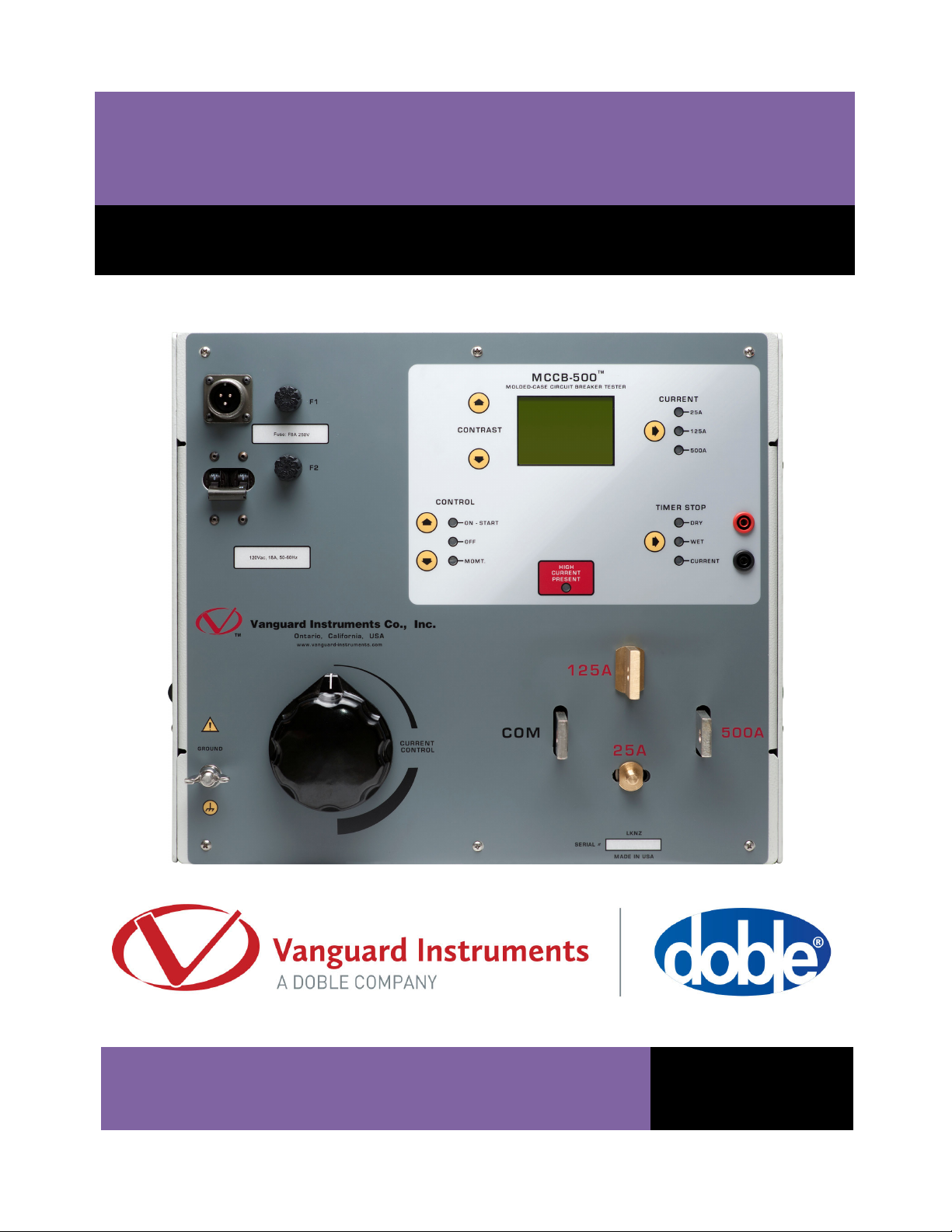
TheVanguardMCCB‐500isamicroprocessor‐basedhighcurrentcircuitbreakertestset.This
unitprovidesavariablehighcurrentsource,control,metering,andtimingcircuitriesfortesting
overloadrelaysandthermalandmagneticcircuitbreakers.
Built-in Timer
TheMCCB‐500'sbuilt‐intimerdisplaysthetestresultsinmillisecondsandcycles.Thecycletime
(50or60Hz)isselectablebytheuser.Timerreadingrangeisfrom0.1msto2hours.Timer
resolutionis0.1msandthetimeraccuracyis±0.1%ofreading,±0.1ms.
NOTE
Fortimerreadingrangeof100s999stheresolutionis1ms.
Fortimerreadingrangeof1000s7200stheresolutionis10ms.
TimerStartMode:Timercanbestartedwhenthecurrentsourceisturnedon.
TimerStopMode:Timercanbestoppedwiththeremovalofthetestcurrentordetectionofa
statuschangeofdrycontactorvoltageinput.
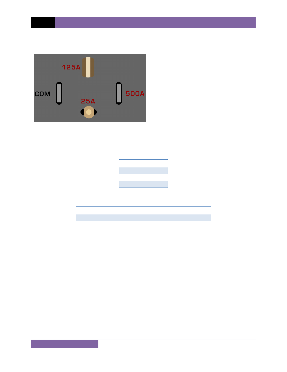
Current Source
TheMCCB‐500'scurrentsourcehas3outputs:500A@4vac,125A@14Vac,and25A@70Vac.
Thecurrentsourcescanoutputshort‐durationoverloadconditions.Thisfeatureisconvenient
forperforminginstantaneoustriptestsofmoldedcasecircuitbreakers,ortestingthetime
delaycharacteristicsofmagneticoverloadrelays.
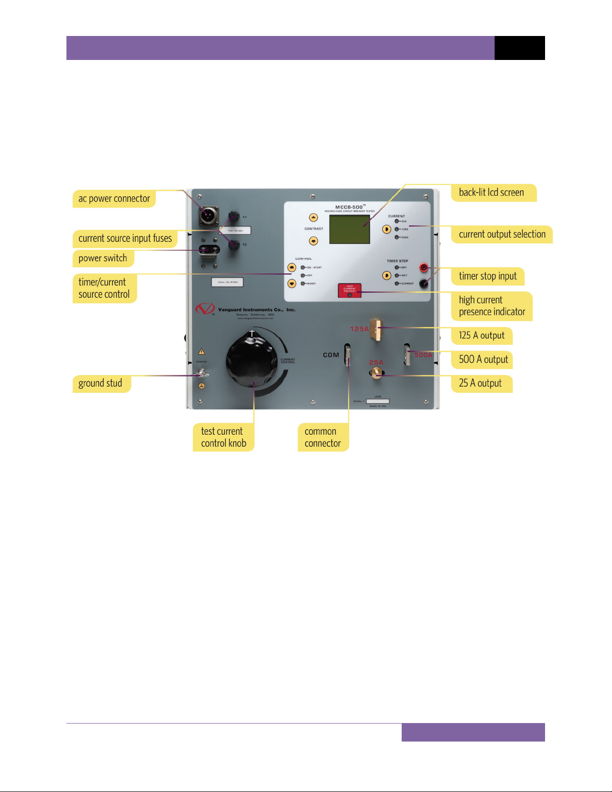
Testcurrentismeasuredanddisplayedona128x64pixelback‐litLCDscreenthatisclearly
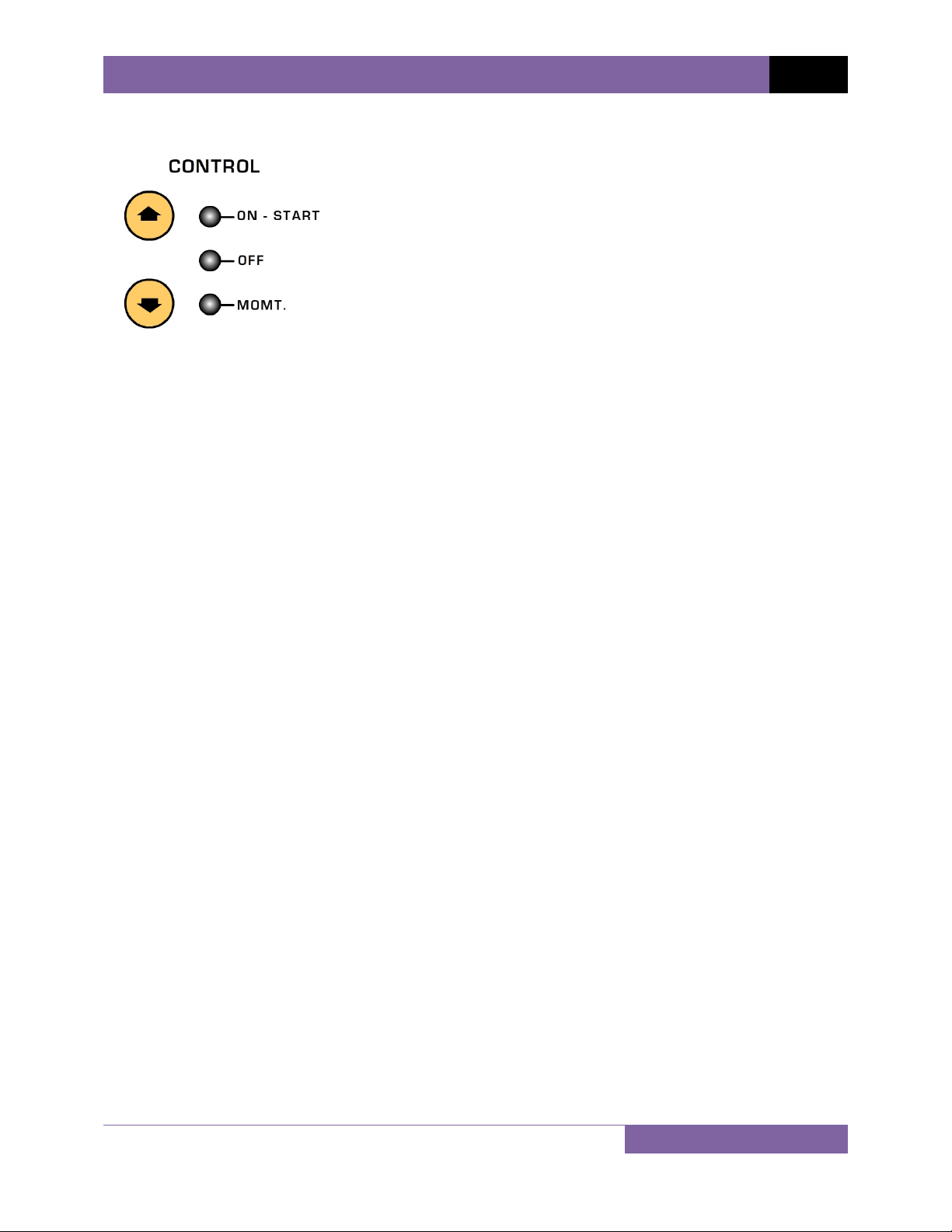
visibleindirectsunlightorlowlightlevels.Controlswitchesareusedtoturnthecurrentsource
onandoff,selectthetimerstopinputtype(currentmode,drycontact,orwetcontact),and
controltheLCDcontrast.
A"momentary"modecanturnonthecurrentsource,capturingthecurrentreadingand
displayingthevalueontheLCD.Thisfeaturecanbeusedtosetthetestcurrentandminimizes
thepossibilityofoverheatingthedeviceundertest.
Testcurrentisturnedonatthezerocrossingpointusingasolidstatedeviceforreliabilityand
precisiontiming.
Built-in Current Meter
TheMCCB‐500featuresabuilt‐incurrentmeterthatdisplaysthetestcurrent(100mA3000A).
Currentreadingaccuracyis:±1%ofreading,±2digits.Testresults(currentreadingandtime)
areretainedafterperformingatestsothatthetestresultscanbereviewed.Thisisa
convenientfeaturewhenusedwiththemomentarymodetopresetthetestcurrenttoavoid
overheatingthecircuitbreaker.

MCCB‐500USER’SMANUALREV1.1
3
Current Source Thermal Protection
Builtinthermalsensorallowsthemicroprocessortomonitorthetransformercurrentsource
operatingtemperature.
1.2 Furnished Accessories
TheMCCB‐500comesfurnishedwiththefollowing:
Two5‐foot(1.5m)#2/0currentcables
Two8‐foot(2.5m)externaltimerinputcableswithalligatorclips.
Onegroundcable
Onepowercord

REV1.1 MCCB‐500USER’SMANUAL
4
1.3 MCCB-500 Technical Specifications
Table 1. MCCB-500 Technical Specifications
TYPE 500 Ampere current source
PHYSICAL SPECIFICATIONS Dimensions: 16”W x 14”H x 13”D (40.6 cm x 35.5 cm x 33.0 cm);
Weight: 93 lbs (42.2 kg)
INPUT VOLTAGE 100 – 120 Vac or 200 – 240 Vac (factory pre-set), 50/60 Hz
INTERNAL CURRENT METER 1A – 3,000A;
accuracy: 1% of reading, ±2 digits
MEASUREMENT METHOD Isolated CT
TIMER STOP INPUTS Voltage input (20V – 300V, dc or peak ac), dry contact input, or removal
of test current
TIMER READING RANGE 0.1ms – 2 hours (also displayed in cycles);
accuracy: 0.1% of reading, ±0.1ms
OUTPUT CURRENTS 500A @ 4V, 125A @ 14V, 25A @ 70V
DISPLAY back-lit LCD screen (128 x 64 pixels); viewable in bright sunlight and low-
light levels
HUMIDITY 90% RH @ 40°C (104°F) non-condensing
SAFETY designed to meet IEC61010 (1995), UL61010A-1, CSA-C22.2 standards
ENVIRONMENT Operating: -10˚C to 50˚C (15˚F to +122˚F);
Storage: -30˚C to 70˚C (-22˚F to +158˚F)
ALTITUDE 2,000 m (6,562 ft) to full safety specifications
CABLES two 5-foot (1.5m) #2/0 current cables, two 8-foot (2.5m) external timer
input cables with alligator clips, one ground cable, one power cord
FURNISHED ACCESSORIES shipping case
WARRANTY one year on parts and labor
NOTE
Theabovespecificationsarevalidatnominaloperatingvoltageandata
temperatureof25C(77F).Specificationsmaychangewithoutpriornotice.

MCCB‐500USER’SMANUALREV1.1
5
1.4 Controls and Indicators
TheMCCB‐500’scontrolsandindicatorsareshowninFigure1.Thepurposeofthecontrolsand
indicatorsmayseemobvious,butusersshouldbecomefamiliarwiththembeforeusingthe
MCCB‐500.Accidentalmisuseofthecontrolswillusuallycausenoseriousharm.Usersshould
alsobefamiliarwiththesafetysummaryfoundonthefrontpageofthisUser’sManual.
Figure 1. MCCB-500 Controls and Indicators

REV1.1 MCCB‐500USER’SMANUAL
6
2.0 FUNCTIONAL DESCRIPTION
2.1 MCCB-500 AC Current Source
TheMCCB‐500providesthreeACcurrentoutputs.ACtestcurrentissetbythe[CURRENT
CONTROL]knob.ThistestcurrentismeasuredanddisplayedontheLCDscreen.TheMCCB‐
500’soutputcurrentratingsareshowninTable2andTable3below.
Table 2. MCCB-500 Current Output
CURRENT OUTPUT
500A @ 4V
125A @ 14V
25A @ 70V
Table 3. MCCB-500 Overload Current Output
CURRENT ON TIME OFF TIME
40% (200A) Continuous Continuous
100% (500A) 30 minutes 30 minutes
NOTE:TheMCCB‐500iscapableofdelivering2500Ainstantaneouscurrent.

MCCB‐500USER’SMANUALREV1.1
7
2.2 MCCB-500 Current Output Control
TheMCCB‐500currentsourceoutputiscontrolledbythe[]
and[]keys.Threecontrolmodesareavailable:ON‐START,
OFF,andMOMT.
TheOFFmodeindicatesthatboththecurrentsourceoutput
andtimerareoff.
TheMOMTmodeturnsonthecurrentsourcemomentarily.To
turnonthecurrentsource,pressandholdthe[]key.TheLED
indicatornexttothe“MOMT”labelwillturnonindicatingthat
theMCCB‐500currentsourceison.TheoutputcurrentwillalsobedisplayedontheLCDscreen
andthelastcurrentreadingremainsdisplayedonthescreen.TheMCCB‐500currentoutput
cannowbesetbyturningthe[CURRENT CONTROL]knob.Releasethe[]keytoturnoff
thecurrentsource.
TheON‐STARTmodeturnsontheMCCB‐500currentsourceandtimer.Thisinitiatesatestand
isstoppedbyusingthe[TIMER STOP]inputs.ThetestresultswillbedisplayedontheLCD
screen.Thetestcanalsobeterminatedbypressingthe[]key.

REV1.1 MCCB‐500USER’SMANUAL
8
2.3 Timer Stop Input and Control
Afteratestisstarted,theMCCB‐500timercanbe
stoppedandthecurrentsourceturnedoffusingoneof
threemodes:drycontactinput,wetcontactinput,or
interruptionoftheMCCB‐500'scurrentoutput.The[]
keyisusedtoselectthedesiredmode.
WhentheDRYCONTACTmodeisselected,theMCCB‐
500willoutputaDCvoltagetothe[TIMER STOP]
terminalstosensethestateofthedrycontacts.A
changeinthisdrycontactstatewillstopthetimerandturnoffthecurrentsource.
InWETCONTACTmode,theMCCB‐500willsenseanACorDCvoltageappliedtothe[TIMER
STOP]terminals.TheOFFstateisavoltagefrom0to10Vac/dc.TheONstateisavoltage
from24to300Vac/dc.Achangeinthevoltagestatewillstopthetimerandturnoffthe
currentsource.
InCURRENTmode,aninterruptionoftheMCCB‐500'scurrentsourceoutput(CBcontact
opened)willstopthetimerandturnoffthecurrentsource.
BoththeDRYCONTACTandWETCONTACTmodesrequireanexternalinputtotheMCCB‐500
viathe[TIMER STOP]terminals.
NOTE
TheMCCBdefaultstoCURRENTmodewhenitisfirstturnedon.

MCCB‐500USER’SMANUALREV1.1
9
2.4 MCCB-500 Timer
TheMCCB‐500’sbuilt‐intime/cyclecountercanbeusedtotimeeventsinmillisecondsand
cycles.TheelapsedtimeisdisplayedontheLCDscreen(inmillisecondsandcycles)alongwith
thetestcurrentafteratestiscompleted.AtypicaltestresultsscreenisshowninFigure2.The
timeristurnedonwhentheON‐STARTmodeisselected.
Figure 2. Typical MCCB-500 Test Results Screen
2.5 LCD Contrast Control
ToadjusttheLCDscreen’scontrast,pressand
holdthe[]keynexttotheLCDscreento
increasethecontrastorthe[]keytodecrease
thecontrast.Releasethekeywhenthedesired
contrastlevelhasbeenreached.
NOTE
TheMCCB‐500willstorethecurrentLCDsettinginnon‐volatilememory.

REV1.1 MCCB‐500USER’SMANUAL
10
2.6 50/60 Hz Cycle Time Selection
Totogglebetweenthe50and60Hzcycletimes,pressandholdboththe[] and
[]keystotheleftoftheLCDscreen.Themessage"50HzSet!"or"60HzSet!"
willbedisplayedontheLCDscreen.Thisvalueisalsodisplayedonthetestresults
screen.

MCCB‐500USER’SMANUALREV1.1
11
3.0 OPERATING PROCEDURES
3.1 Testing the Time Delay of a Low Voltage Circuit Breaker
Figure3illustratesatypicalconnectionoftheMCCB‐500toamoldedcasecircuitbreakerto
testits“OpenTimeDelay”.TheMCCB‐500injectsatestcurrentthroughacircuitbreaker
contact.Thiscurrentissensedbythecircuitbreakercontrolcircuit.Thetimedelayteststarts
byinjectingapresetcurrenttothecircuitbreakercontactandendswhenthecircuitbreaker
contactisopenedandinterruptsthetestcurrent.
Figure 3. Typical MCCB-500 Application

REV1.1 MCCB‐500USER’SMANUAL
12
Usethestepsbelowtotestthetimedelayofaprotectionrelay:
a. ConnecttheSafetyGroundtotheMCCB‐500.
b. ConnecttheACpowercord.
c. ConnecttheCurrentCablesfromtheMCCB‐500tothebusasshowninFigure3.
d. Turnthe[CURRENT CONTROL]knobtozero.
e. Turnonthe[POWER SWITCH].
f. Holdthe[]keytomomentarilyturnonthecurrentsource.
g. Turnthe[CURRENT CONTROL]knobtosetthedesiredcurrent.
h. Releasethe[]key.
i. Pressthe[]keytoselecttheON‐STARTmodeandstartthetest.TheMCCB‐500will
injectthepresetcurrentintothebusandturnonthetimer.Thetimerwillstopandthe
currentsourcewillbeturnedoffwhenthecircuitbreakerisopened.AtypicalMCCB‐
500timedelaytestresultsscreenisshownbelow:
NOTE
Intheabovetest,thetimerwillbestoppedifthecurrentsourceis
interrupted(circuitbreakeropened).Thetestresultswillbedisplayedand
remaindisplayedonthescreen.Ifthetestisabortedbytheoperator,thelast
testresultswillbedisplayedandremaindisplayedonthescreen.


Copyright2015byVanguardInstrumentsCompany,Inc.
MCCB‐500User’sManualRevision1.1November10,2020TA
Table of contents
Other Vanguard Instruments Test Equipment manuals

Vanguard Instruments
Vanguard Instruments VBT-75P User manual

Vanguard Instruments
Vanguard Instruments EZCT Use and care manual

Vanguard Instruments
Vanguard Instruments CVT-765 User manual

Vanguard Instruments
Vanguard Instruments VBT-75 S2 User manual

Vanguard Instruments
Vanguard Instruments EZCT-2000C User manual

Vanguard Instruments
Vanguard Instruments EZCT S2 User manual

Vanguard Instruments
Vanguard Instruments EZCT User manual

Vanguard Instruments
Vanguard Instruments VBT-75P S2 User manual

Vanguard Instruments
Vanguard Instruments EZCT Manual

Vanguard Instruments
Vanguard Instruments VBT-75 User manual