SandSun VA08H Series User manual

使 用 說 明 書
OPERATION MANUAL
超 負 荷 保 護 裝 置
OVERLOAD PROTECTOR
MODEL:VA08H (Air Pressure Type)
山 田 順 精 機 股 份 有 限 公 司
SANDSUN PRECISION MACHINERY CO.,LTD
Tel : 886-4-8536688
Fax : 886-4-8536699
http://www.sandsun.com.tw
E-mail: sandsun@ms26.hinet.net
台灣省彰化縣大村鄉中山路三段 57 巷 7 號
NO .7, LANE 57, SEC.3, CHUNG-SHAN RD.,
DAH-TSUEN, CHANG-HWA, TAIWAN, R.O.C.

CONTENTS
1. INTRODUCTION - - - - - - - - - - - - - - - - - - - - - - - - - - - - - - - - - - - - - - - - - - - - - - 1
2. SELECTION OF MODEL - - - - - - - - - - - - - - - - - - - - - - - - - - - - - - - - - - - - - - - - - 1
3. SPECIFICATION - - - - - - - - - - - - - - - - - - - - - - - - - - - - - - - - - - - - - - - - - - - - - - 1
4. BASIS OF SELECTION - - - - - - - - - - - - - - - - - - - - - - - - - - - - - - - - - - - - - - - - - - 2
5. ATTENTION POINTS FOR PIPING - - - - - - - - - - - - - - - - - - - - - - - - - - - - - - - - - - 2
6. CAUTION IN USE - - - - - - - - - - - - - - - - - - - - - - - - - - - - - - - - - - - - - - - - - - - - - - 3
7. METHOD OF AIR DRAIN - - - - - - - - - - - - - - - - - - - - - - - - - - - - - - - - - - - - - - - - - 3
8. WORKING PRINCIPLE - - - - - - - - - - - - - - - - - - - - - - - - - - - - - - - - - - - - - - - - - - 4
9. SETTING METHOD OF LIMIT SWITCH - - - - - - - - - - - - - - - - - - - - - - - - - - - - - - - 5
10. TROUBLESHOOTING - - - - - - - - - - - - - - - - - - - - - - - - - - - - - - - - - - - - - - - - - - - 6
11. PUMP ASSEMBLY DIAGRAM - - - - - - - - - - - - - - - - - - - - - - - - - - - - - - - - - - - - - - 7
12. OVERLOAD VAVLE ASSEMBLY DIAGRAM - - - - - - - - - - - - - - - - - - - - - - - - - - - - 8
13. OUTLINE DIMENSIONS - - - - - - - - - - - - - - - - - - - - - - - - - - - - - - - - - - - - - - - - - 9

OVERLOAD PROTECTOR
1. Introduction:
Overload protector is installed on press in order to check the overload hydraulic
pressure of cylinder inside the slide. The hydraulic pressure of cylinder will be
released immediately within 3/1000 seconds when overload occurs. And press will
stop working urgently as soon as receiving the signal from limit switch, in order to
protect the die and press.
After overload occurred, will quickly compensate oil of cylinder to reach normal
working pressure by air driven hydraulic pump, in order to operate the press normally.
Furthermore, overload protector to have pressure control valve, which can prevent
effects of excessive rising of hydraulic pressure caused by raised temperature when
press is operating.
2. Selection of Model: V A 0 8 H- □
1 □
2 □
3 (Suitable for press 200 tons & down)
Setting range of
overload hydraulic
pressure (Kgf/cm2)
Type of limit switch Volume of oil tank
(Liter)
7:x 70 times
9:x 90 times
2 : NO type
6 : NC type
0: None
1: 1.2
3: 4.0
5: 8.0
3. Specification:
2007.10.17 SANDSUN 1
Model VA08H-7□0 VA08H-9□0
Releasing flow rate cm3/sec 13000 11500
Area of orifice cm2 0.5 0.4
Method of setting pressure Air pressure
x 70 times
Air pressure
x 90 times
Range of setting pressure kgf/cm2 250 ~ 350 270 ~ 450
Air supply kgf/cm2 3 ~ 5
Capacity of press 200 ton & down
Air consumption Nl/min 220
Maxi. noise dB 77
Discharging pressure of pump kgf/cm2 Air pressure x 42 times
Hydraulic oil ISO-VG-32 or equivalent

OVERLOAD PROTECTOR
4. Basis of Selection:
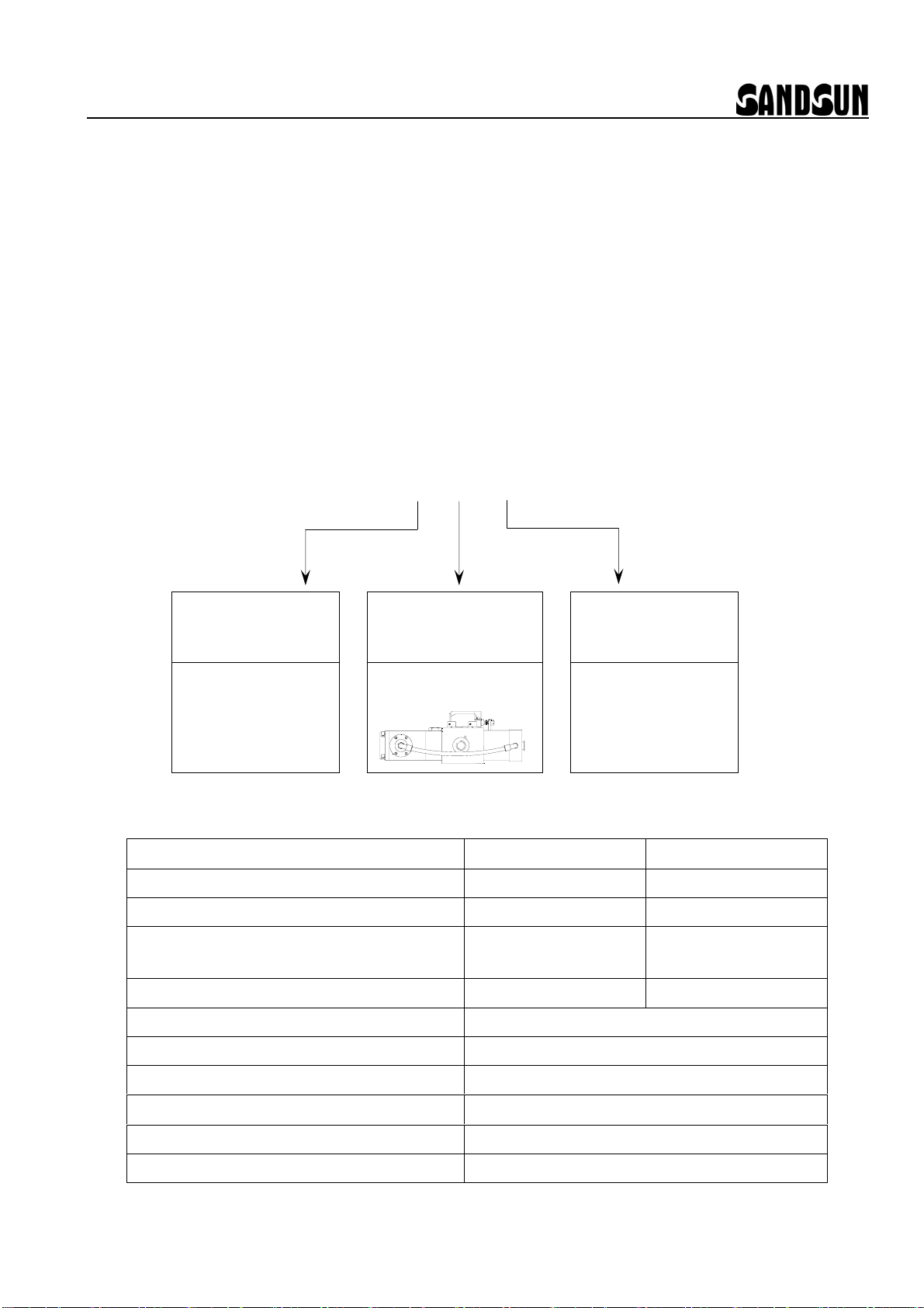
4.1 Specification & parameter of press
F:capacity of press (tons)
S:stroke length of slide (mm)
N:strokes per minute (spm)
H:rated tonnage point (mm)
D:diameter of cylinder inside slide (cm)
n:number of cylinder inside slide (pc)
h:stroke length of cylinder inside slide (cm)
Pa: air pressure (kgf/cm2)
m : times of air pressure
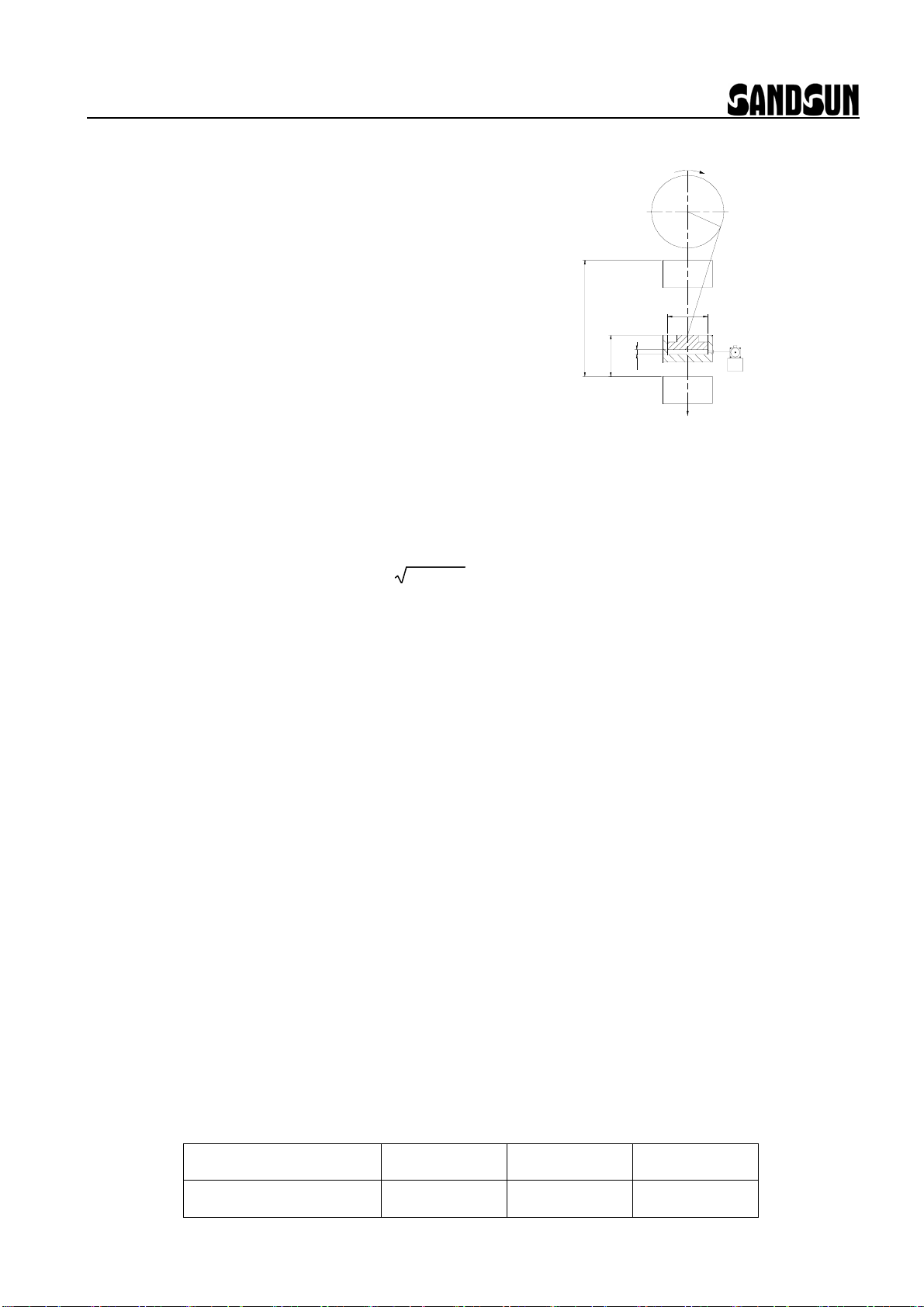
4.2 Calculation formulas for model selection
˙Total area of cylinder inside slide A=(πD2 / 4) x n (cm2)
˙Setting hydraulic pressure of overload protector P = Fx 1000 x 1.1 / A (kgf/cm2)
˙Setting air pressure of overload protector Pa=P / m (kgf/cm2)
˙Drop speed of slide V=N SH-H2 / 87.5 (cm/sec)
˙Releasing flow rate of cylinder inside slide when overload occurs Q=A x V (cm3/sec)
˙Volume of oil tank L ≧ 4 x A x h (cm3)
4.3 Determination of model no.
˙ Please choose a suitable model from below table according to releasing flow rate of cylinder
inside slide (Q)
˙ Releasing flow rate of overload protector which you choose has to be more than of cylinder
inside slide when overload occurs. (Please consider use two sets of overload protector if
releasing flow rate is not enough. It’s equal to 2 times of releasing flow rate)
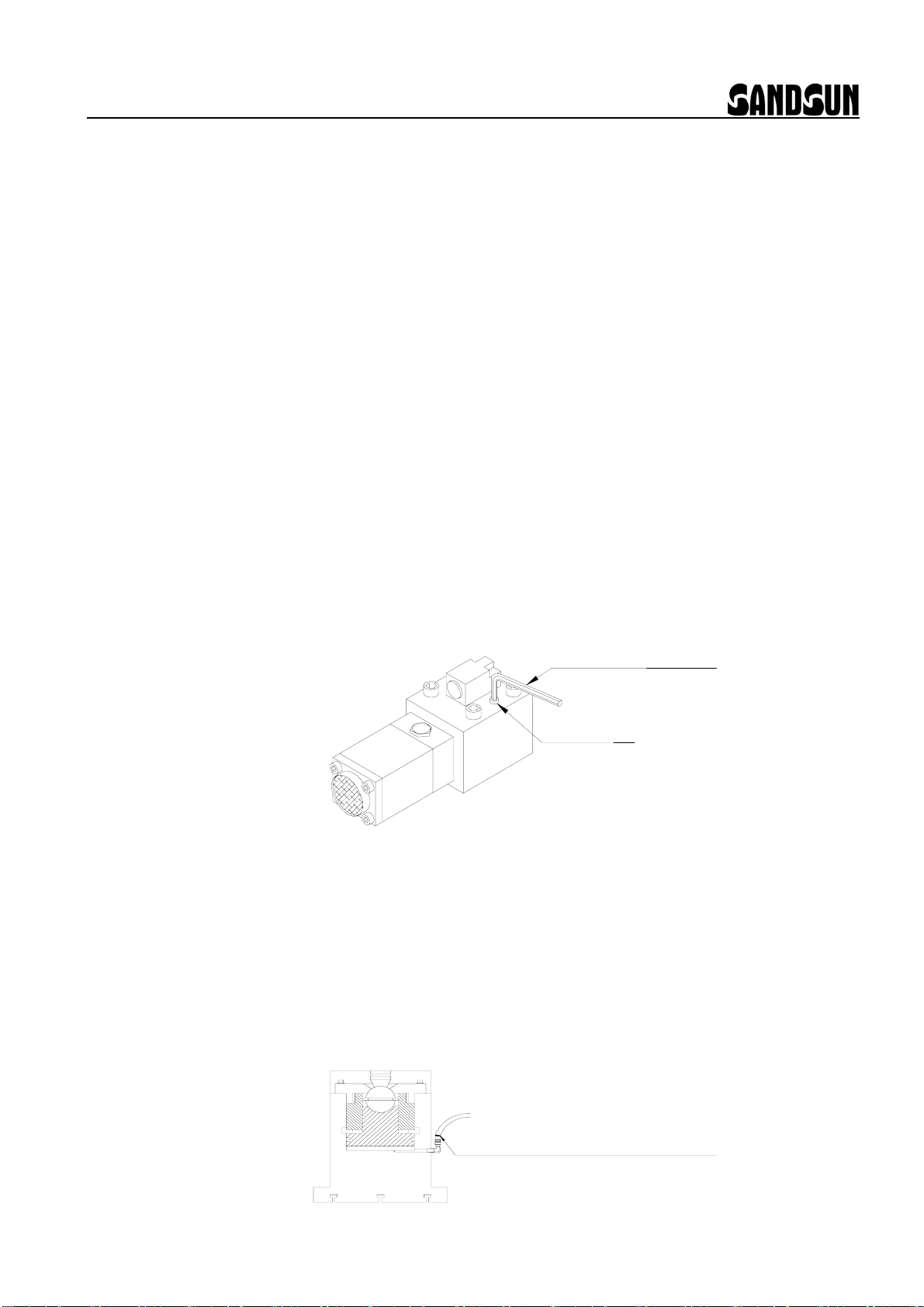
5. Attention Points for Piping:
5.1 Air piping:
a. Inside diameter of air piping has to be more than 6 mm.
b. Air supply has to remove steam and keep dry, in order to avoid generate furring.
The function of pump and other parts will be affected or damaged by furring.
c. Please choose normal close type (NC) of air solenoid valve either 2-way or 3-way
to use.
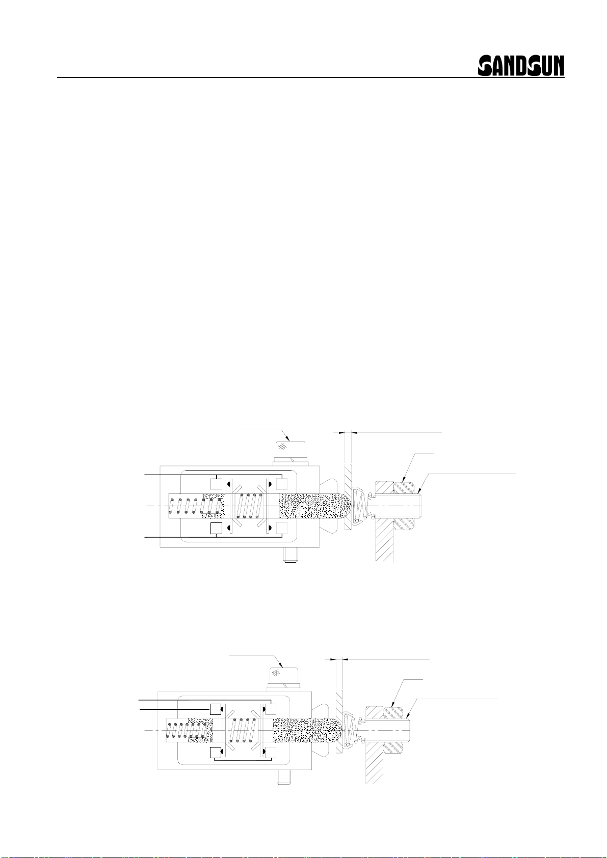
5.2 Hydraulic piping:
a. 1 In order to prevent normal function of overload protector or damage to inside parts
from dust or chips, Hydraulic piping & fitting has to be cleared completely and keep clean.
b. Size of piping for reference:
SANDSUN 2
Size (I.D. / O.D.) 12 / 18 mm 13 / 18 mm 14 / 18 mm
Work pressure (max.) 400 kgf/cm2 320 kgf/cm2 250 kgf/cm2
N
D
S
Hh
OVERLOAD
F

OVERLOAD PROTECTOR
6. Caution in Use:
6.1 Please check before use if wire connection is correct & air-piping connection is correct
& hydraulic oil in tank is enough & kind of hydraulic oil is suitable.
6.2 When press is normally operated, air supply should not be turned off absolutely.
6.3 Check the oil tank regularly to see if there still has enough hydraulic oil. If lower than
mid position of the oil level gauge, please add oil immediately.
6.4 The hydraulic oil should be changed every year.
7. Method of Air Drain: (when you use overload protector at first time or re-supply oil)
7.1 At air drain bolt:
7.1.1 Adjust air regulator to 2 ~ 3 kgf/cm2.
7.1.2 Turn the air drain bolt anti-clockwise around 1/4 ~ 1/2 circle, then pump starts
working.
7.1.3 Wait for around 20 seconds in order to exhaust air completely.
7.1.4 Turn the air drain bolt clockwise to fasten it, and then pump stops working
(hydraulic pressure is raising).
7.1.5 If the pump still working. It means the air didn’t exhaust completely, please
repeat step 7.1.2 ~ 7.1.4. till air is exhausted completely.
7.1.6 Adjust air regulator to required pressure.
7.2 At connector between high-pressure hose and cylinder of the slide:
7.2.1 Adjust air regulator to 2 ~ 3 kgf/cm2.
7.2.2 Loosen the connector of high-pressure hose from slide, then pump starts working.
7.2.3 Check the oil is which flowed out of high-pressure hose, till the oil didn’t bubbles
completely, then fasten the connector.
7.2.4 After fasten the connector of high-pressure hose, pump stops working (hydraulic
pressure is raising).
7.2.5 Adjust air regulator to required pressure.
SANDSUN 3
Hexagon wrench (5mm)
Air drain bolt
High-pressure hose connector

OVERLOAD PROTECTOR
8. Working Principle:
8.1 Press is normally operate:
When the press is normally operate, inner to have pressure control valve of overload
protector, which has the function of auto adjust hydraulic pressure. It can prevent effects
of excessive rising of hydraulic pressure caused by raised temperature when press is
operating.
8.2 When overload protector is releasing:
When overload occurs, overload protector will work to release excessive pressure
immediately. Meanwhile, it will out put electric signal to stop press immediately, and
the air solenoid valve, which is used by overload protector, will be“OFF”(cut off the
power supply).
8.3 After overload protector was released. (or hydraulic pressure isn’t enough):
After overload occurred, you have to eliminate the overload situation or to reset the
press; Meanwhile, the air solenoid valve is “ON” (electrify) to supplement oil of
cylinder to reach normal working pressure. Press will return to normal operation.
2005.07.08 SANDSUN 4
Circuit of Limit Switch NO type(AT11-1-I) NC type(AT11-2-I)common
Press is normally
operate
14
13
22
21
OFF
14
13
22
21
ON
When overload
protector is
releasing
14
13
22
21
ON 14
13
22
21
OFF
After overload
protector was
released
(or hydraulic
pressure isn’t
enough)
14
13
22
21
ON 14
13
22
21
OFF

OVERLOAD PROTECTOR
9. Setting Method of Limit Switch:
9.1 Installation method:
Use 3 mm hexagon wrench to fasten 2 pc of M4x25 hexagon socket head bolts, which
is thread locking on the end 2 ~ 3 threads of bolts to prevent loose of limit switch.
Before fasten the bolts.
9.2 Adjust method:
Limit switch has to be adjusted on the normal use condition of overload protector.
(It means hydraulic pressures of cylinder inside the slide is charged completely
then pump stops working). Under this condition, Insert the thickness gauge of 0.8
& 1.0 mm each between adjustable screw and head of limit switch to adjust limit
switch. After adjustable screw, please fasten the nut and then insert the thickness
gauge to re-confirm if electric signal is correct.
9.2.1 NO type(AT11-1-I) :
Contact point 13 & 14 of limit switch has to be “ON” when insert 1.0 mm
thickness gauge. And to be “OFF” when insert 0.8 mm thickness gauge.
0.8 & 1.0mm
Nut
Thickness Gauge
14
13
22
2-M4x25
21
Adjustable Screw
9.2.2 NC type(AT11-2-I):
Contact point 21 & 22 of limit switch has to be “OFF” when insert 1.0 mm
thickness gauge. And to be “ON” when insert 0.8 mm thickness gauge.
0.8 & 1.0mm
Nut
Thickness Gauge
13
14 22
2-M4x25
21
Adjustable Screw
2006.12.04 SANDSUN 5

OVERLOAD PROTECTOR
10. Troubleshooting:
Item Trouble Cause Step for Solution
1. Air supply was closed. Open the air supply.
2. Exchange valve ○
37 caught by fur. Disassemble the pump for
cleaning then smear the grease.
3. Spring ○
13 broke. Change the spring
4. Spool ○
11 caught. Check if any damage happens
from the oil seal ○
26 and spool
○
11 .
Ⅰ Pump not work
5. Air pressure is too low or not
enough.
Adjust the air pressure to over 3
kgf/cm2
1. Exchange valve ○
37 caught by fur. Disassemble the pump for
cleaning then smear the grease.
Ⅱ Air leak from the
pump
2. The O-ring ○
10 of the exchange
valve was damaged.
Change the O-ring.
1. Oil seal ○
26 damaged. Change the oil seal.
The
pump 2. Inlet valve ○
20 damaged or caught. Check if any damage happens
from the inlet base ○
24 and inlet
valve ○
20 .
3. Without enough oil in the oil tank. Refill hydraulic oil,and let the air
drain.
4. Pilot valve ○
29 caught. Check if any damage happens
from the pilot valve.
Ⅲ Pump
nonstop
(highest
speed)
The
overload
valve
5. Air drain bolt ○
40 loosen. Fasten the air drain bolt.
Piping 1. Oil leak out from outer piping. Find out the leakage position then
fasten it.
2. Inlet valve ○
20 damaged. Check if any damage happens
from the inlet base ○
24 and inlet
valve ○
20 .
The pump
3. The pressure valve automatically
adjusts pressure due to the air
pressure is too high now.
Adjust the air pressure to lower
than 5 kgf/cm2.
4. O-Ring ○
36 damaged. Change the O-ring.
5. Pressure control valve ○
27
damaged.
Change the pressure control
valve.
Ⅳ Pump
nonstop
(lower
speed)
The
overload
valve
6. Air drain bolt ○
40 not lock. Fasten the air drain bolt.
2006.12.04 SANDSUN 6

17
16
18
19
20
23
21
15
22
423335 34 3032 31 10 29 2542
10 28 27 26 24
61-6001
61-5007
ARP-568-015
AS-50
61-6100
61-5300
61-6200
61-5400
61-3200
61-3300
ARP-568-022
61-3100
61-2000
AP-44
61-4100
61-4400
61-4207
61-4300
ARP-568-010
M4x10
Specification
6.0
19
20
19A
21
15
17
16
18
Hydraulic body
Steel ball
Inlet valve
Check pad
Spring
O-Ring
O-Ring
Spring
11
13
12
10
9
8
7
6
Item
2
3
4
1
14
Bolt
Cylinder body
Spring base
O-Ring
Spool
Spring
Outlet base
O-Ring
Piston
Air Supply base
Part Name
Filter plate
O-Ring
Filter
Exchange valve
Check ring
Silencer plate
Buffer pad
SAN
D
SUN
1
1
1
1
1
1
1
1
Spring
39
41
42
40
Bolt
Cover
Silencer
37
38
35
36
M6x90
61-2800
61-2400
61-2500
R-45
61-2600
61-2700
61-5700
Inlet valve base
Spool bush
Bush-(2)
Bush-(1)
Pilot base
Back-up ring
Inlet base
Part Name
26
4Oil seal
4
1
1
1
1
1
1
1
30 O-Ring
O-Ring
O-Ring
O-Ring
32
33
34
31
28
29
27
Qt'y
1
1
1
1
22 O-Ring
24
25
23
Item
UN-7.1
61-2100
TF-7.1-17.1-2
61-2200
ARP-568-028
ARP-568-017
61-2300
ARP-568-021
ARP-568-032
Specification
61-5200
61-5500
61-5607
ARP-568-020
OVERLOAD PROTECTOR
3
11. PUMP ASSEMBLY DIAGRAM (Model:VP-5007)
41 40 2
1
10
37
36
32
38
39
40
7
468911
10 12 13 14
7
1
1
2
2
1
2
1
2
1
1
2
1
1
1
1
1
11
1
1
1
1
Qt'y
2007.10.17

SANDSUN
OVERLOAD PROTECTOR
12. OVERLOAD VALVE ASSEMBLY DIAGRAM (Model:VA08H)
8
38
27
26
28
29
30
31
32
33
35
37
36
41
40
34
Item
Limit switch base
Limit switch
Coupled piston
Relief valve
Coupled plate
Balance pistion
Part Name
14 O-Ring
O-Ring
25
Cover
Cylinder
O-Ring
Bolt
21
23
24
22
16
20
15
4
Spring
O-Ring
O-Ring
Nut
Bolt
10
12
13
11
6
7
5
Bolt
Bolt
Item
2
3
1
1
AS-50
AS-15
61-1100
61-1300
61-1200
61-0630
61-1000
AS-3
M8x70
1
1
1
1
1
4
1
1
61-7100
AS-46
AS-24
61-1400
TM14x30
AT11-1-I(NO)
Specification
M5x12
M6
M4x25
M4x4
1
2
1
1
1
11
1
1
Qt'y
1
2
1
61-0510
61-0401
61-0309
61-0307
BP-12.5
61-0200
TP-12.5
61-1501
61-0100
Specification
BP-16
O-Ring
Air drain bolt
Hydraulic body
Flat pad
O-Ring
O-Ring AP-7
M4
BP-4
Back-up ring
Pressure control valve
Pilot valve base
Part Name
Spring
O-Ring
O-Ring
Pilot valve
O-Ring
O-Ring
BP-16
AP-24
AS-35
1
1
1
1
2
1
1
1
1
11
1
11
11
1
Qt'y
1
1
11
AT11-2-I(NC) 1
(VA08-7口口)
(VA08-9口口)
Adjustable screw 61-1700
2007.10.17
35 34 33 28
31
32 29 27
30 26
36
37
138 273
25 24 23 22 21 20
13
11
10 12 10 14 15 16
456
A
40
41
39
39 Filter A00011

OVERLOAD PROTECTOR
13. Outline DimensionsVA08□-□□0:
121
Pump Suction Port
97
57 33
Pump
3
8.5 19
Thank Port
41
13.2 22.5
O Ring P-16
19
O Ring P-16
Cylinder Port
27.3 11
52
O Ring P-24
60
70
Limit Switch
82
277
PT1/2
Overload Cylinder Port
74
Air Drain Bolt
13 70 33
PT1/4
Air Supply Port
D
C
A
B
D
C
E
16-d
2005.07.08 SANDSUN 9
Model VA08□-□61 VA08□-□63
A 206 285
B 230 310
C 50 80
D 100 150
E 226 276
d ø11 ø13
L 1.2 4.0
L :Volume of oil tank
(
Liter
)
This manual suits for next models
4
Table of contents
Other SandSun Test Equipment manuals