Kohler TT-1757 User manual

TT-1757 7/18a
INSTALLATION INSTRUCTIONS
Original Issue Date: 5/18
Model: Generator Sets with APM402 or Decision--Makerr3000 Controller
Market: Industrial and Residential/Light Commercial
Subject: GM104661, APM402 Controller Service Replacement Kit
Introduction
The controller service replacement kit is available to
replace a non-functional controller. Use the following
procedure to install the replacement controller. See
Figure 1 for typical controller identification. For features
and operation of the controller, see the operation
manual in the literature kit.
Note: Use the APM402 as a service replacement for the
Decision-Makerr3000. The personality profile
and configuration file from a Decision-Makerr
3000 can be imported into an APM402, however,
a profile from a APM402 cannot be loaded onto a
Decision-Makerr3000, even if the original profile
was designed for a Decision-Makerr3000. Also
Decision-Makerr3000 is not a service
replacement for an APM402.
Note: The APM402 controller uses different firmware
than the Decision-Makerr3000 controller. Do
not attempt to load Decision-Makerr3000
firmware on an APM402 controller, or vice-versa.
Note: WHEN REPLACING DECISION-MAKERr
3000 CONTROLLERS, FIRMWARE IN OTHER
KOHLER ACCESSORIES SUCH AS RSA II,
RSA III AND MODBUS/ETHERNET
CONVERTER NEEDS TO BE UPDATED TO
FUNCTION PROPERLY. Modbus/Ethernet
converter requires both SNMP firmware update
and a .MIB file update. Monitor III software does
not require any updating; however, the APM402
appears as a Decision-Makerr3000 in this
software. Use the following accessory firmware
upgrades available for download in the Service
Support section of the Kohler Power Resource
Center:
DRSA III firmware version 2.02.0 or higher
DRSA II firmware version 2.00 or higher
DModbus/Ethernet converter firmware and
.MIB file released June 2018 or later
1. Mini USB connection
GM65741-
1
Figure 1 APM402 Controller
Note: Do not use this controller replacement installation
instruction for upgrading software.
When replacing the controller, the following data must
be resident for the controller to function. Controller
service replacement kits do not include the three files
installed at the factory. The service technician must
install the three files into the replacement controller.
DApplication program contains the software that
controls system operation. The application file was
preprogrammed in the original controller at the
factory.
DPersonality profile is specific to the engine and
alternator and was preprogrammed in the original
controller at the factory.
A backup disk of the personality profile and
application program is supplied with the literature
packet shipped with the generator set. Typically, the
distributor stores this disk for possible future use such
as controller replacement or other circumstances
requiring a backup.

2TT-1757 7/18
Note: If the personality disk is NOT available, request
a replacement from the manufacturer using the
generator set serial number or order number.
DUser parameters unique to an installation include
timer values, setpoints, generator set data such as
voltage and input/output selections. These
parameters are typically set up for or by the installer at
the time of installation. User parameters are typically
recorded on the personality profile disk, a separate
backup disk/drive, or written in the Programmer-
Defined Settings appendix in the controller operation
manual. A copy of the Programmer-Defined Settings
form is included at the end of this document.
Note: If the user parameters are included on the
personality disk, the disk label should indicate
Site Program—Yes.
Read the entire installation procedure and compare the
kit parts with the parts list in this publication before
beginning installation. Perform the steps in the order
shown.
Always observe applicable local and national electrical
codes.
Note: The following service kit procedure changes only
the controller. If the generator set requires
voltage reconnection and/or frequency
adjustment, see the controller operation manual.
Installation Requirements
The following items are necessary PC requirements for
installing the controller service replacement kits.
DSiteTechtSoftware from the Kohler Power
Resource Center (KPRC). Go to Service Support and
click on Software to download to your PC hard drive, if
not already installed on your PC.
DTP-6701 SiteTechtSoftware Operation Manual
available from the literature section in Kohler Power
Resource Center (KPRC).
DUSB Cable with male USB-A and mini-B connectors.
See TP-6701.
Safety Precautions
Observe the following safety precautions while installing
the kit.
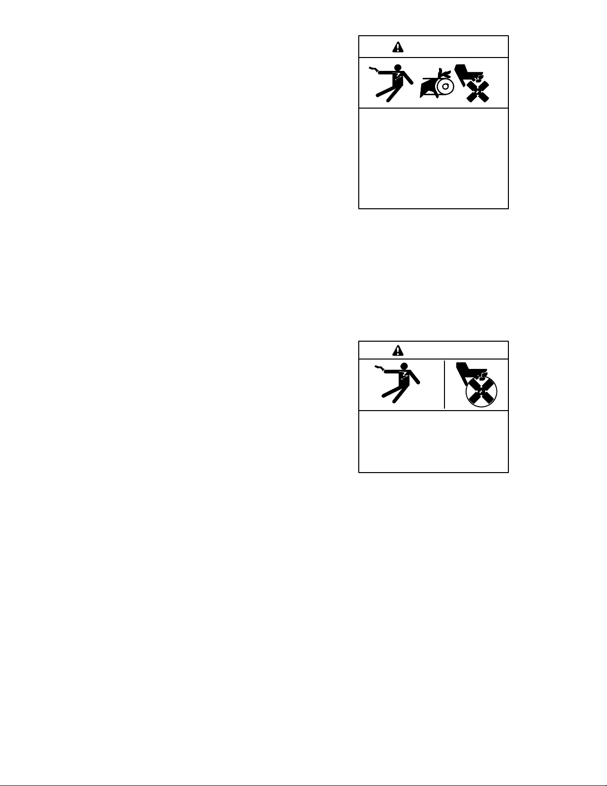
Accidental starting.
Can cause severe injury or death.
Disconnect the battery cables before
working on the generator set.
Remove the negative (--) lead first
when disconnecting the battery.
Reconnect the negative (--) lead last
when reconnecting the battery.
WARNING
Disabling the generator set. Accidental starting can
cause severe injury or death. Before working on the
generator set or equipment connected to the set, disable the
generator set as follows: (1) Move the generator set master
switch to the OFF position. (2) Disconnect the power to the
battery charger. (3) Remove the battery cables, negative (--)
lead first. Reconnect the negative (--) lead last when
reconnecting the battery. Follow these precautions to prevent
starting of the generator set by an automatic transfer switch,
remote start/stop switch, or engine start command from a
remote computer.
Hazardous voltage. Moving parts.
Will cause severe injury or death.
Operate the generator set only when
all guards and electrical enclosures
areinplace.
DANGER
Grounding electrical equipment. Hazardous voltage will
cause severe injury or death. Electrocution is possible
whenever electricity is present. Ensure you comply with all
applicable codes and standards. Electrically ground the
generator set and related equipment and electrical circuits.
Turn off the main circuit breakers of all power sources before
servicing the equipment. Never contact electrical leads or
appliances when standing in water or on wet ground because
these conditions increase the risk of electrocution.
Connecting the battery and the battery charger.
Hazardous voltage will cause severe injury or death.
Reconnect the battery correctly, positive to positive and
negative to negative, to avoid electrical shock and damage to
the battery charger and battery(ies). Have a qualified
electrician install the battery(ies).

TT-1757 7/18 3
Short circuits. Hazardous voltage/current will cause
severe injury or death. Short circuits can cause bodily injury
and/or equipment damage.Do not contact electrical
connections with tools or jewelry while making adjustments or
repairs. Remove all jewelry before servicing the equipment.
Installation Procedure
1. Acquire the user parameters.
1.1 Read and follow all safety precautions at the
beginning of this publication.
1.2 Choose one of the following methods to retrieve
the user parameters:
DBackup disk. If a backup disk was
previously made, obtain the parameters
from this disk. If a disk was not previously
made, create a backup if possible using the
SiteTechtsoftware. The existing controller
must function in order to create the file.
DPaper form. Parameters may have been
previously recorded on the User-Defined
Settings form located in the appendix of the
Controller Operation Manual or other similar
form.
DController menu. Manually review the
controller menu displays if possible and
enter the parameter information in the
Controller Operation Manual appendix,
Programmer-Defined Settings form.
1.3 Save the user parameter data for step 6.3.
2. Remove the generator set from service.
2.1 Press the generator set master control
OFF/RESET button.
2.2 Disconnect the power to the battery charger, if
equipped.
2.3 Disconnect the generator set engine starting
battery(ies), negative (--) lead first.
2.4 Disconnect the generator set from load by
opening the line circuit breaker.
3. Remove the existing controller and
disconnect the electrical connections.
3.1 Remove the junction box panels as needed to
access the wiring.
3.2 Remove the four controller panel screws.
Note: Clearly mark all disconnected leads from
the controller with tape to simplify
reconnection.
3.3 Disconnect the controller harness leads. Listed
below are some common leads and plugs that
require removal or disconnection. Items below
in bold are shown in Figure 2 and Figure 3.
These connections are typical and may not
apply to all applications. See the corresponding
wiring diagram found in the respective wiring
diagrams manual.
DRemote Emergency Stop Switch
connections.
DP1 (24-Pin) Connector for engine/
generator wiring harness.
DP2 (6-Pin) Connector for AC current. P2 is
only used on older versions of the
Decision--MakerR3000 (GM65741, green
board) controller. Newer versions of the
Decision--MakerR3000 (GM65741--1) and
APM402 controllers have the AC current
wiring included in the P1 connector. An
adapter harness may be required; see step
4.1.
D(4) Push-on Terminal Connectors for
V7/V8/V9/V0 for generator set output
voltage connection.
DP21 (6-Pin) Connector for RS-485
connection of optional RSA.
DP23 (8-Pin) Connector (RJ45) for optional
input/output (I/O) module circuit board.
DP30 3-Pin Connector (2-Pin Jumper) for
selection of alternator type—Wound Field
(300 kW and larger) or Fast Response (less
than 350 kW). Take note of the original
circuit board jumper position. See Figure 5.
DTB1 (6-Position) Terminal Block for
analog and digital inputs.
DTB2 (4-Position) Terminal Block for K1
relay outputs.
DTB3 (6-Position) Terminal Block for
E-stop, remote start contacts, and aux. input
connections.

4TT-1757 7/18
DAny other external leads to the controller
1. Main logic circuit board
2. Emergency stop switch GM65741-
1
2
Figure 2 Main Circuit Board and E-Stop Switch
1. (4) push-on terminal connectors
2. TB2 4-position terminal block
3. TB3 6-position terminal block
4. P2 6-pin connector (only used with older Decision-MakerR
3000 controllers, GM64345 green board)
5. P1 24-pin connector
6. TB1 6-position terminal block
7. P30 jumper (Wound Field or Fast Response)
8. P23 8-pin connector (RJ45)
9. P21 6-pin connector (for RS-485 communications)
GM64345-1-A
4
5
6
8
9
3
1
2
7
Figure 3 Main Circuit Board Connectors
4. Reconnect the electrical connections
and install the replacement controller.
4.1 Connect the generator set wiring P1 plug to the
controller P1 connector.
Note: If replacing an older Decision--MakerR
3000 (GM65741) controller that has a P2
plug, order the adapter harness,
GM86898. Connect the P1 and P2 plugs
to the adapter harness, and then connect
the adapter harness into the controller
P1 connector. See Figure 6.
4.2 Reconnect all of the remaining electrical
connections disconnected in step 3.3. Refer to
Figure 2 and Figure 3.
4.3 Place the P30 jumper in the appropriate position
based on the alternator: Wound Field (300 kW
and larger) or Fast Response (less than
350 kW). The wound field position is the factory
default. Refer to the original circuit board jumper
position and see Figure 4 and Figure 5.
Note: P30 is not included on early versions of
the Decision-MakerR3000 (GM65741
with GM64345-1 green board).
Alternator Type P30 Position
4P,4Q,4S,4UA,4V Fast Response
4PX, 4QX, 4RX, 4SX, 4TX Fast Response
4M, 5M, 7M Wound Field
Figure 4 P30 Jumper Positions
1. P30 with jumper in Wound Field position
2. P30 with jumper in Fast Response position
GM64345-1-A
2
1
Figure 5 P30 3-Pin Connector and 2-Pin Jumper
4.4 Align the controller panel with the mounting
holes and install four screws.
4.5 Replace the junction box panels if previously
removed.

TT-1757 7/18 5
GM86898-
Generator set P1
wiring harness plug
Generator set P2
(6-Pin) wiring harness
plug for AC current
wiring
Connect to controller
P1 connector
Connect to controller
P1 connector
Generator set P1
wiring harness plug
(includes AC
current wiring)
Adapter Harness not used
Adapter Harness GM86898
Figure 6 Adapter Harness GM86898 Application
5. Restore power to the generator set.
5.1 Reconnect the generator set engine starting
battery, negative (--) lead last.
5.2 Reconnect power to the battery charger, if
equipped.
6. Set the device profile.
6.1 Connect the PC to the APM402 controller using
a USB cable. See Figure 1 for the location of the
USB connection port.
6.2 Insert the personality profile backup disk/drive
and load the data. Refer to TP-6701 SiteTecht
Software Operation Manual for details.
6.3 Choose one of the following methods to load the
user parameters.
DBackup disk/drive. Use a PC with SiteTecht
software to load the data from the user
parameter backup disk/drive.
Note: The personality profile and
configuration file from a
Decision-Makerr3000 can be
imported into an APM402.
DPaper form. Use a PC to enter the user
parameter data from the filled-out Controller
Operation Manual appendix, the Appendix
A-Programmer-Defined Settings form
located at the end of this document, or other
similar form.
6.4 Create a new user parameter data backup file if
any changes are made using SiteTecht
software. Refer to TP-6701 SiteTechtSoftware
Operation Manual for details.
6.5 Disconnect the USB cable.
6.6 Power down the unit by using the prime power
switch (if equipped) or by disconnecting the
battery negative (--) terminal.
6.7 Wait at least 15 seconds and then power up the
unit by using the prime power switch (if
equipped) or by reconnecting the battery
negative (--) terminal.

6TT-1757 7/18
6.8 Refer to the Controller Operation Manual.
Calibrate the generator set as instructed in the
Generator Metering Section.
6.9 Press the RUN button to start the generator set.
6.10 Test the functionality of the controller by
reviewing the menus and observing the system
status lamps. Use the Operation Manual as
needed.
6.11 Press the OFF button to stop the generator set
after completing the test.
6.12 Reconnect the generator set to load by closing
the line circuit breaker.
6.13 Press the generator set master control AUTO
button for startup by remote transfer switch or
remote start/stop switch.

TT-1757 7/18 7
Appendix A Programmer-Defined Settings
Use the table below to record programmer-defined
settings during the generator set controller setup and
calibration. The controller default settings and ranges
provide guidelines. The table contains all faults with
ranges and time delays including items that do not have
adjustments. Some notices give the programmer a
choice to make them active Not adjustable
programmer-defined settings result when the controller
logic does not allow changes or the values are engine
limited.
SiteTechtsoftware is required for programming the APM402
controller. Contact your local distributor/dealer for assistance.
Note: Inhibit time delay is the time delay period after
crank disconnect.
Note: The engine ECM may limit the crank cycle even if
the controller is set to a longer time period.
Programmer-Defined Settings
Description
Controller Display
Message
Write
Access
Display
SiteTech
GenSet
Mode
Always
Running
Stopped
Range
Setting
Default
Selection
Time
Delay
Range
(sec.)
Default
Time
Delay
(sec.)
Programmer-
Defined
Settings
Engine Functions
Critically high fuel level
(diesel-powered models only) *
Fuel Level Critically
High 0--100% 95% 0--10 5
ECM communications loss ECMCommErr
Shutdwn Fixed 10 Not adjustable
ECM diagnostics (multiple
inputs) [ECM xxxxxx Warning Not adjustable
ECM diagnostics (multiple
inputs) [ECM xxxxxx Shutdwn Not adjustable
ECM faults (address conflict) ECM Addr Err
Shutdwn Not adjustable
ECM faults (model mismatch) ECM Mismatch
Shutdwn 0--255 0
Engine over speed Eng Speed High
Shutdwn S A 105--120% 115%
Engine RPM
(manual speed adjust)
Version 3.10.3 or higher Engine RPM Display DS A
60 Hz:
1751--1849
50Hz:
1451--1549
60 Hz:
1800
50 Hz:
1500
Engine start aid active Starting Aid Notice
Engine under speed Eng Speed Low
Shutdwn S A 75--95% 85%
Fuel tank leak * Fuel Leak Warning Not adjustable
Fuel tank leak * Fuel Leak Shutdwn Not adjustable
High battery voltage Battery High Warning S A 110--135% 125% Fixed 10 Not adjustable
High coolant temperature Coolnt Temp High
Warning
0--10
(0--30
inhibit)
5
(0
inhibit)
High coolant temperature Coolnt Temp High
Shutdwn
0--10
(0--30
inhibit)
5
(0
inhibit)
High fuel level (diesel-powered
models only) *
Fuel Level High
Warning 0--100% 90% 0--10 5
Loss of fuel Loss of fuel Not adjustable
Low battery voltage Battery Low Warning S A 80--105% 100% Fixed 90 Not adjustable
Low coolant level * Coolant Lvl Low
Shutdwn Fixed 5Not adjustable
Low coolant temperature Coolant Temp Low
Warning Fixed 16_C
(60_F)
0--10
(0--30
inhibit)
5
(0
inhibit)
Low cranking voltage Lo Crank Vlt Warning Fixed 60% Fixed 6Not adjustable
Low engine oil level * Oil Level Low Warning Not adjustable

8TT-1757 7/18
Description
Programmer-
Defined
Settings
Default
Time
Delay
(sec.)
Time
Delay
Range
(sec.)
Default
Selection
Range
Setting
GenSet
Mode
Always
Running
Stopped
Write
Access
Display
SiteTech
Controller Display
Message
Low engine oil level * Oil Level Low
Shutdwn Not adjustable
Low fuel level (diesel models) * Fuel Level Low
Warning 0--100% 35% 0--10 10
Low fuel level (diesel models) * Fuel Level Low
Shutdwn 0--100% 5% 0--10 0
Low fuel pressure
(gas models) *
Fuel Press Low
Warning Not adjustable
Low oil pressure Oil Press Low
Warning
Fixed
(Fixed
inhibit)
5
(5
inhibit)
Not adjustable
Low oil pressure Oil Press Low
Shutdwn
Fixed
(Fixed
inhibit)
5
(5
inhibit)
Not adjustable
No coolant temperature signal Temp Sig Loss
Shutdwn Not adjustable
No oil pressure signal Press Sig Loss
Shutdwn Fixed 5Not adjustable
Overcrank Over Crank Shutdwn Fixed (30
inhibit) Not adjustable
Speed sensor fault Spd Sens Flt Warning Not adjustable
General Functions
Alarm silence, 0--Auto only
(NFPA 110), 1--Always AlarmSilenceMode S A 0--1 1
Aux. inputs 0--5 VDC, 1 analog Aux Input Warning 0--100% 100% 0--10 0
Aux. inputs 0--5 VDC, 1 analog Aux Input Shutdwn 0--100% 100% 0--10 0
Auxiliary inputs, up to 3 digital
(2 additional digital inputs
available with I/O module
option)
Aux Input Warning
0--10
(0--30
inhibit)
0(0
inhibit)
Auxiliary inputs, up to 3 digital
(2 additional digital inputs
available with I/O module
option)
Aux Input Shutdwn
0--10
(0--30
inhibit)
0(0
inhibit)
Backup parameters loaded Backup Pars Status Not adjustable
Battery charger 1
communication loss Bat1CommLoss Not adjustable
Battery charger 2
communication loss Bat2CommLoss Not adjustable
Battery charger fault *
(* does not apply to charger
GM87448)
Batt Chg Flt Warning Not adjustable
Battery charger identity conflict BatIdErr Not adjustable
Battery charger parameter
mismatch ParMisatch Not adjustable
Battery fault Battery Flt Not adjustable
Chicago code active * Auto Locked Notice
Common fault Common Fault
Shutdwn Not adjustable
Common warning Common Warng Not adjustable
Contrast (see NO TAG GenSet
System) Contrast Display D A 1--10 5
Default parameters loaded Default Pars Warning Not adjustable
Emergency stop Emerg Stop Shutdwn Not adjustable
Enclosure temperature: high
shutdown
Enclsr Temp: High
Shutdwn S R Fixed Active Fixed 5(20
inhibit) Not adjustable
Engine cooldown (delay) active Eng Cooldown Notice
Engine start delay active Start Delay Notice

TT-1757 7/18 9
Description
Programmer-
Defined
Settings
Default
Time
Delay
(sec.)
Time
Delay
Range
(sec.)
Default
Selection
Range
Setting
GenSet
Mode
Always
Running
Stopped
Write
Access
Display
SiteTech
Controller Display
Message
Engine started Engine Start Status Not adjustable
Engine stopped Engine Stop Status Not adjustable
EPS supplying load Emerg Pwr On Notice Not adjustable
File system error (controller
fault) File Error Shutdwn Not adjustable
Generator running Gen Running Notice Not adjustable
Input/output (optional module
board) communication loss OB1 Com Loss Not adjustable
Internal failure Intern Error Shutdwn Not adjustable
Measurement Units,
0--English, 1--Metric Measurement Display DS A0--1 1
Metering communication loss MeterCommLos
Shutdwn Not adjustable
NFPA 110 alarm active NFPA Alarm Notice
Not in auto (master control
buttons) Not In Auto Warning Not adjustable
Prime power application,
0--Standby, 1--Prime Power Type DS A0--1 0
Remote start Remote Start Status Not adjustable
System ready System Ready Status Not adjustable
System timer failed TimerErrorNotice Not adjustable
Generator Functions
AC sensing loss AC Sens Loss
Warning Not adjustable
AC sensing loss AC Sens Loss
Shutdwn Fixed 3Not adjustable
Alternator protection Alt Protect Shutdwn Not adjustable
Ground fault input * Ground Fault Warning Not adjustable
kW overload
Total Power High
Shutdwn Fixed
102%
standby,
112%
prime
Fixed 60 Not adjustable
Locked rotor (failed to crank) Locked Rotor
Shutdwn S A 1--5 5
Overfrequency Freq High Shutdwn 102--140% 110% Fixed 10 Not adjustable
Overvoltage (each phase) Volts (L1--L2, L2--L3,
or L3--L1) High
Shutdwn
S A 105--135% 120% 2--10 2
Power rating Pwr Rating DS S10--5000 275
System frequency System Freq DS S50--60 60
System voltage System Volt DS S110--600 208
Underfrequency Frequency Low
Shutdwn 80--95% 90% Fixed 10 ST
60 LT Not adjustable
Undervoltage (each phase) Volts (L1--L2, L2--L3,
or L3--L1) Low
Shutdwn
S A 70--95% 80% 5--30 10
Voltage/phase configuration,
0--Single phase, 1--Single
phase dogleg, 2--three phase
wye, 3--three phase delta
SystemPhase DS S0--3 2
Voltage regulator average
voltage adjustment VR Volt Adj DS R108--600 208
(Voltage) regulator
communication loss
RegCommLoss
Shutdwn Not adjustable
SiteTech Read/Write Display Only
Charger Absorption Current
Termination Target (A) S A 1–5 2

10 TT-1757 7/18
Description
Programmer-
Defined
Settings
Default
Time
Delay
(sec.)
Time
Delay
Range
(sec.)
Default
Selection
Range
Setting
GenSet
Mode
Always
Running
Stopped
Write
Access
Display
SiteTech
Controller Display
Message
Charger Automatic Equalize
Enable
Note: Equalize is only
available with FLA/VRLA
topology selected.
S A Active
Inactive Inactive
Charger Charge Cycles
Between Auto Equalize Cycles
Note: Equalize is only
available with FLA/VRLA
topology selected.
S A 0–99
Adjustable with
Charger Custom
Profile enabled.
Charger Custom Profile Enable S A Active
Inactive Inactive
Charger Depleted Battery
Current Limit S A 1–5 2
Charger Depleted Battery
Voltage Target S A
4–12
(12 V)
18–24
(24 V)
10
(12 V)
20
(24 V)
Adjustable with
Charger Custom
Profile enabled.
Charger Equalize Stage
Duration (Min)
Note: Equalize is only
available with FLA/VRLA
topology selected.
S A 60 – 480
Charger Manual Equalize
Cycle Activation
Note: Equalize is only
available with FLA/VRLA
topology selected.
S A Active
Inactive Inactive
Charger Maximum Absorption
Time Threshold (Min.) S A
60 – 360
60 – 600
(NiCad
only)
240
Adjustable with
Charger Custom
Profile enabled.
Charger Maximum Bulk Time
Threshold (Min) S A 60 – 600 480
Adjustable with
Charger Custom
Profile enabled.
Charger Refresh Charge Cycle
Time (Hr) S A 0,
23 – 672 335
Charger Return To Bulk State
Voltage Threshold (V) S A
10–13
(12 V)**
20–26
(24 V)**
12.8
(12 V)
25.6
(24 V)
Adjustable with
Charger Custom
Profile enabled.
Charger Starter Battery
Topology
Note: Verify that the battery
topology is set correctly for the
battery type that is used.
Incorrect charger output
system voltage may cause
irreversible damage to the
battery and abnormal out
gassing.
S A
Default
FLA/VRLA
AGM
Gel
NiCad
Default
Charger System Battery
Voltage
Note: Verify that the system
voltage is set correctly for the
battery type that is used.
Incorrect charger output
system voltage may cause
irreversible damage to the
battery and abnormal out
gassing.
S A
System 12
VDC
System 24
VDC
12 VDC
Charger Temperature
Compensation Enable S A Active
Inactive Inactive

TT-1757 7/18 11
Description
Programmer-
Defined
Settings
Default
Time
Delay
(sec.)
Time
Delay
Range
(sec.)
Default
Selection
Range
Setting
GenSet
Mode
Always
Running
Stopped
Write
Access
Display
SiteTech
Controller Display
Message
Charger Temperature
Compensation Slope (mV/_C) S A
--40–0
(12 V)
-80–0
(24 V)
-30
(12 V)
-- 6 0
(24 V)
Adjustable with
Charger Custom
Profile enabled.
Charger Voltage Absorption
(V) S A
13–15
(12 V)**
26–30
(24 V)**
14.25
(12 V)
28.5
(24 V)
Adjustable with
Charger Custom
Profile enabled.
Charger Voltage Bulk (V)
S A
13–15
(12 V)**
26–30
(24 V)**
14.25
(12 V)
28.5
(24 V)
Adjustable with
Charger Custom
Profile enabled.
Charger Voltage Equalize (V)
Note: Equalize is only
available with FLA/VRLA
topology selected.
S A
14–16
(12 V)
28–32
(24 V)
Adjustable with
Charger Custom
Profile enabled.
Charger Voltage Float (V)
S A
13–14
(12 V)**
26–28
(24 V)**
13.25
(12 V)
26.5
(24 V)
Adjustable with
Charger Custom
Profile enabled.
Current transformer ratio ]S S 1-- 1200
ECM power S S 0--1 0
Engine cooldown delay S A 0--600 300
Engine (cyclic) crank on S A 10--30 15
Engine (cyclic) crank pause S A 1--60 15
Engine ECM start delay S A 0--300 0
Engine idle duration S A 0--60 60
Engine no. of (cyclic) crank
cycles S S 1--6 3
Engine restart delay S A 1--10 10
Engine start aid delay S A 0--10 0
Engine start delay S A 0--300 0
Equalize Current Limit (A)
Note: Equalize is only
available with FLA/VRLA
topology selected.
S A 1–5
Adjustable with
Charger Custom
Profile enabled.
Forced Charge Cycle Reset S A Active
Inactive Inactive
Output Enable Reduced Out S A Fixed Active
Voltage regulator gain S R 1--255 128
Voltage regulator stability
adjust S R 1--255 128
Voltage regulator, volts per
Hertz slope S R 1--10 5
Voltage regulator, volts per
Hertz cutin frequency S R 42--62 57.5
* Some functions require optional input sensors or are engine ECM dependent on some generator set models.
[ECM inputs are engine manufacturer dependent.
]Changeable only by resetting the controller with a personality profile (SiteTech 1.4 or higher).
** Denotes the default parameter range. Typically, ranges for the NiCad battery topology are slightly wider. For more details, refer to the battery
charger operation manual.
ST--Short Term, LT--Long Term

12 TT-1757 7/18
APM402 Controller Service Replacement Kit
Kit: GM104661
Qty. Description Part Number
1Controller Assy, APM402 GM65741--2
1APM402 Replacement Kit Instructions TT-1757
Availability is subject to change without notice. Kohler Co. reserves the
right to change the design or specifications without notice and without any
obligation or liability whatsoever. Contact your local Kohlerrgenerator
set distributor for availability.
2018 by Kohler Co. All rights reserved.
KOHLER CO., Kohler, Wisconsin 53044 USA
Phone 920-457-4441, Fax 920-459-1646
For the nearest sales and service outlet in the
US and Canada, phone 1-800-544-2444
KOHLERPower.com
Table of contents
Other Kohler Batteries Charger manuals