Kohler S450P User manual

Installation and Homeowners Guide
Underscore Bathroom Heater S450P
S450P
K-22488T-2-MZ
K-22488T-2-0
KOHLER CHINA INVESTMENT CO., LTD NO.158, JIANG CHANG SAN ROAD,
JING'AN DISTRICT, SHANGHAI, PRC POST CODE: 200436
( ) 158 200436
1430825-T01-B

-1-
BEFORE YOU BEGIN
!
!
!
!
Please read these instructions carefully to familiarize
yourself with the required tools, materials, and installation
sequences. Follow the sections that pertain to your
particular installation. This will help you avoid costly
mistakes. In addition to proper installation, read all
operation and safety instructions.
All information in these instructions is based upon the
latest product information available at the time of
publication. Kohler China reserves the right to make
changes in product characteristics, packaging, or
availability at any time without notice.
These instructions contain important care, cleaning, and
warranty information -
.
This product complies with GB4706.1-2005, GB4706.23-
2007, GB4706.27-2008, GB7000.1-2015, GB7000.202-
2008, GB/T 17743-2017 and Q31/0106000060C022-2020.
please leave instructions for the
consumer
!
!
!
!
,
-
GB4706.1-2005 GB4706.23-2007
GB4706.27-2008 GB7000.1-2015 GB7000.202-2008
GB/T 17743-2017 Q31/0106000060C022-2020
©
©
Copyright Kohler China Investment Co., Ltd. 2021
2021
WARNING: Risk of electrical shock.
Warning: Danger of electric shock.
Warning:
Warning:
Warning:
Warning:
Warning:
A licensed
electrician should make all electrical connections.
Connect only to
a circuit protected by a typical two-pole circuit breaker.
Disconnect
power before servicing.
The appliance
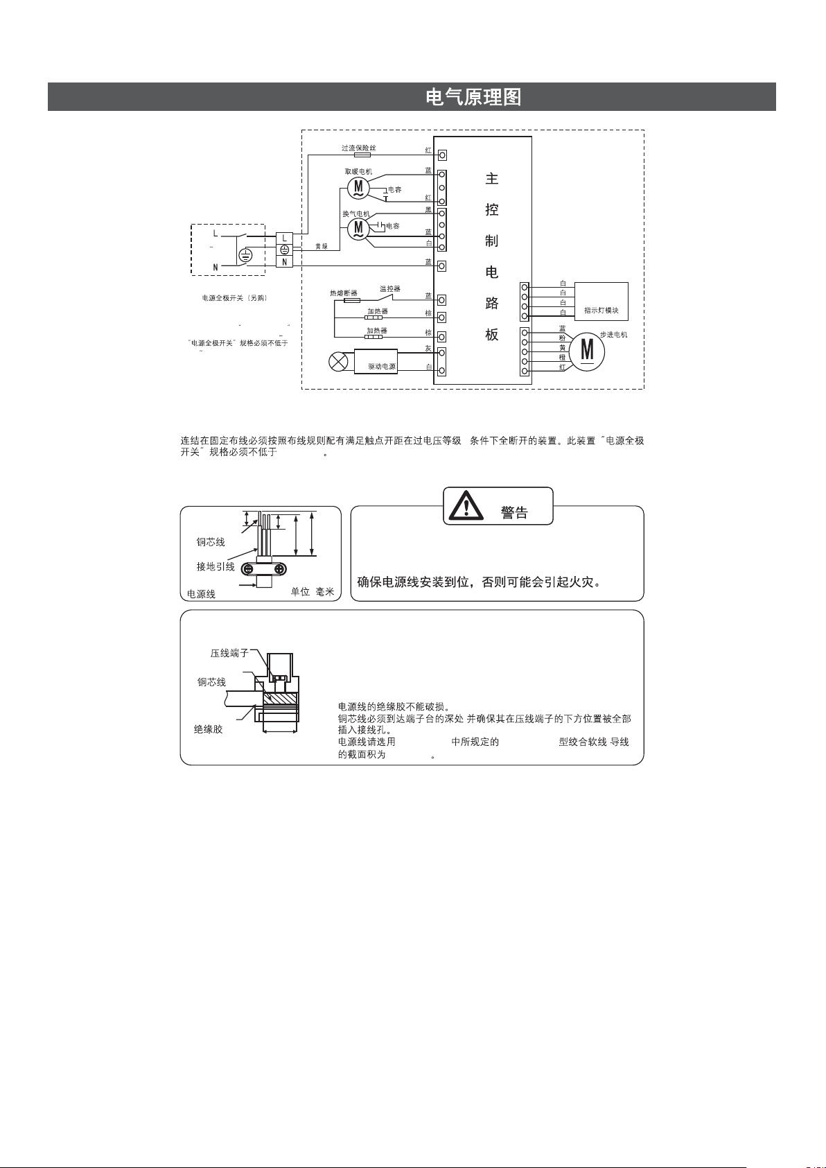
shall be installed according to the national wiring rules.
Otherwise, it may cause electric shock or fire.
This product
must be used under the power supply with leakage
protection switch conforming to CCC (the leakage
current is below 30mA). Otherwise, it may cause
electric shock and fire.
The power must
be cut off before any cleaning and maintenance.
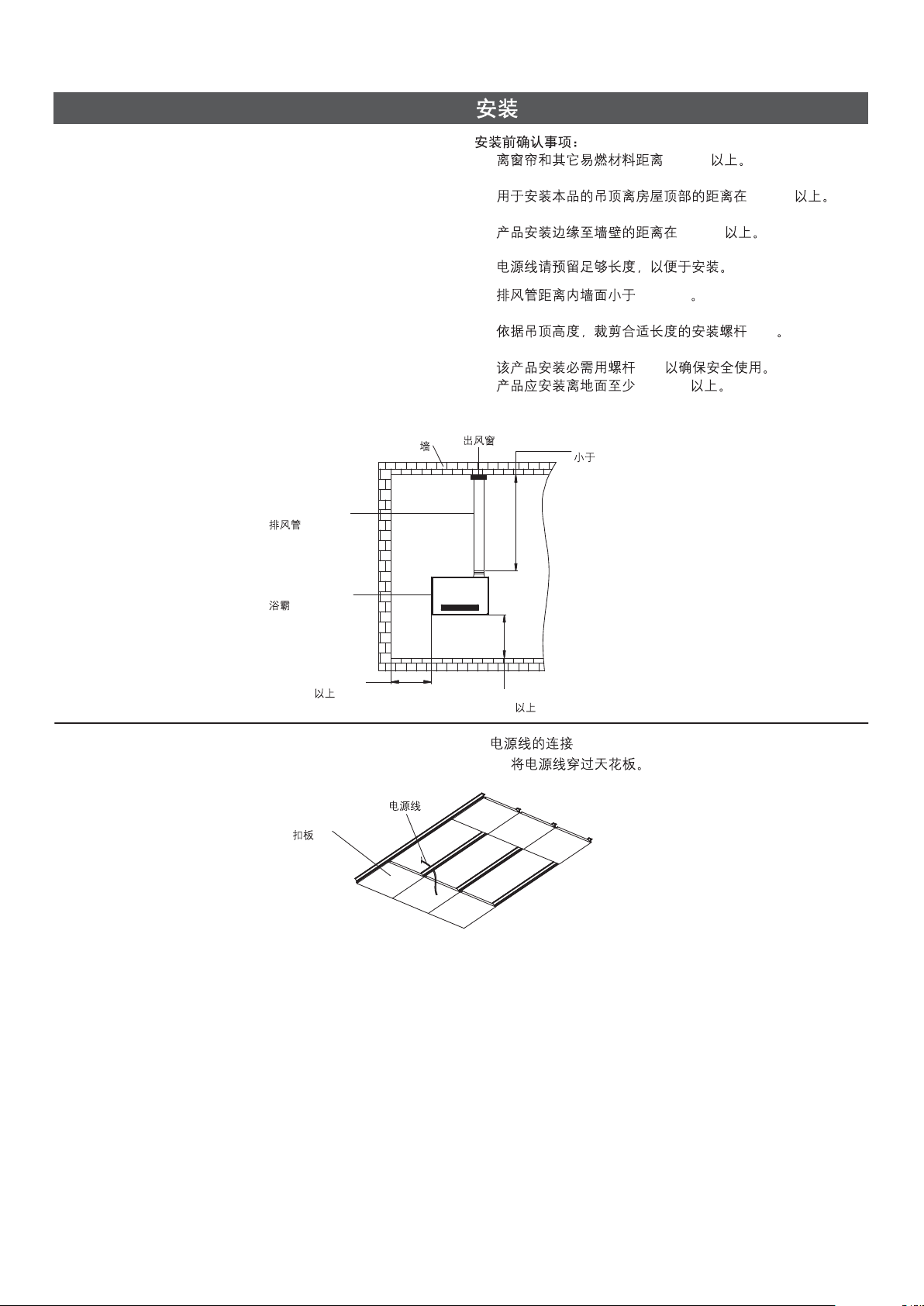
After the installation of the product, the
distance between the bottom of the product and the
ground must be greater than 2.3m.
The installation of the product should make
the switch and other controllers inaccessible to people
in the bathtub or shower area.
It is forbidden to use the power beyond the
rated voltage of 220 V~, 50 Hz. Otherwise, it will
damage the product and cause fire.
In order to avoid the danger caused by the
false reset of the thermal circuit breaker, the appliance
can not be powered by external switching devices,
such as timers or connected to the circuit which is
regularly on and off by common components.
Do not install near curtains and other
combustible materials. Otherwise, combustibles may
be ignited.
CCC
30mA
2.3m
220V 50Hz
1430825-T01-B

Kohler reserves the right to change marked dimensions without prior notice.
!
!
!
!
!
!
!
!
!
!
Tape measure
Level
Screw driver
Connection wire
Wire cutter
Insulation tape
Bushing
Percussion Drill
Pen Knife
Wrench
!
!
!
!
!
!
!
!
!
!
RECOMMENDED TOOLS AND MATERIALSRECOMMENDED TOOLS AND MATERIALS
Unit: mm
:
Reference Value
ROUGHING-IN
Junction Box Cover
49
179
28
10
217
Ventilation Outlet
410
429
300
450
Hot Air Outlet
242
270
290
Warning:
Warning:
Warning:
Warning:
It is forbidden to place the product directly
under the power socket. Otherwise, it may cause fire.
It is forbidden to use methods other than
those specified in this manual for installation.
Otherwise, the product may fall and cause injury.
This product must be grounded safely.
If the power cord is damaged, in order to
avoid danger, it must be replaced by professionals
from the manufacturer, its maintenance department or
similar departments.
-2-
1430825-T01-B

-3-
SPECIFICATIONS
Model K-22488T-2-MZ/K-22488T-2-0 K-22488T-2-MZ/K-22488T-2-0
SIMPLIFIED DIAGRAM OF THE UNIT
Expansion Pipe
M6 Screw Rod
M6
M6 Butterfly Nut
M6 Hanger
BTP4*8 Self Tapping Screw
BTP4*8
Ventilation Outlet Assy.
Air Exhaust Pipe
Clamp
Air Outlet Window
Keel
M6 Nut
M6
6
6
Spring Washer 6Washer
6
BTP4*8 Triangular
Self Tapping Screw
BTP4*8
Note: Plaster or other ceiling opening dimension: 450 X 290 (mm)
450 X 290 (mm)
+5
0
+5
0
+5
0
+5
0
Rated Input Power 2650W 2650W
Heater Power
Fan Power
Dry Clothing Power
Ventilation Power
2638W 2638W
30W 30W
2650W(Hot)/55W(Cool) 2650W( )/55W( )
25W 25W
Lighting Power
Ventilation Volume
Ventilation Noise
Ingress Protection
12W 12W
2.7m /min
32.7m /min
3
39dB (A) 39dB (A)
IPX2 (Bathroom Heater) IPX2 ( )
IPX4 (Remote Control) IPX4 ( )
Rated Voltage
And Frequency 220V~, 50Hz 220V~ 50Hz
LED Ingress Protection
IP20 IP20
!
!
!
!
The rated input power is measured at the factory.
The exhaust air volume, air change noise and other data
are the test results of Kohler company, which are all
central values, which are measured under the static
pressure of 0 Pa. The error of exhaust air volume shall not
be less than 90% of the express value.
The ventilation noise value is A weighted average sound
pressure level, which is the central value of Kohler
company's test results, and the measured value does not
exceed the stated value + 3dB. In the semi anechoic
chamber, five points on the plane 1 meter below the
sample and four points on the plane of the air outlet of the
sample are operated under rated voltage and rated power,
and the average noise value of nine points is taken.
The body of this product has passed the drip-proof water
test and meets the requirements of IPX2.
The above parameters are subject
to change without prior notice
!
!
!
!
0Pa
90%
A
+3dB
15
9
IPX2
1430825-T01-B

8
8
43
23
-4-
+
+
+
+
+
+
There's no risk of damage to the insulation of power cord.
Copper cord must be inserted into the pillar terminal hole, and make
sure all the cords under the terminal are inserted into the pillar
terminal completely.
Suggest using a power cord which with specification 60227 IEC 53
Model's powercord Specified in GB/T 5023.5 and with cross section
of 3X1.5mm .
,
GB/T 5023.5 60227 IEC 53 ,
3X1.5mm
2
2
Terminal
Conductor
Insulation
(Unit: mm)
(: )
WARNING
Make sure the power cord installed firmly,
otherwise it may catch fire.
Conductor
Earth
Power Cord
LED POWER
LED
HEATER 2 2
HEATER 1 1
THERMOSTAT
THERMAL FUSE
OVER CURRENT FUSE
VENT MOTOR
HOT MOTOR
CAPACITOR
CAPACITOR
ALL-POLE SWITCH (OPTIONAL)
220V
50Hz
P1
CN2
CN3
P2
P3
P4
P5
CN4
CN1
CN6
STEPPER MOTOR
INDICATOR LIGHT
MODULE
THE RATE OF THE POWER SWITCH
MUST NOT BE LOWER THAN 250V 20A
250V 20A
YELLOW/GREEN
/
RED
BLUE
BLUE
BLUE
BLUE
BLUE
RED
RED
BLACK
WHITE
WHITE
WHITE
WHITE
WHITE
WHITE
BROWN
BROWN
GRAY
PINK
YELLOW
ORANGE
MAIN CONTROL CIRCUIT BOARD
K-22488T-2-MZ
K-22488T-2-0
WIRING DIAGRAM
8
The fixed wiring of the connection shall be provided with a device to satisfy the full disconnection of the
contact opening under the condition of overvoltage class III in accordance with the wiring rules. The
specification of the power switch must not be less than 250V~20A.
III
250V~20A
1430825-T01-B

-5-
PREPARATIONS BEFORE INSTALLATION
A. Preparation before the installation A.
1. Open the hole of outlet window
Make sure that the outlet window s position (it should be
lower than the outlet of the bathroom heater to prevent the
water come back to the bathroom heater from the outlet
window), and open a round hole on the wall.
2. Outlet window installation
Fix the air exhaust pipe to the outlet window on the wall
with the clamp as the preparation of bathroom heater
installation. Seal the pipe and the outlet window with
foaming agent.
1.
(
)
2.
Ceiling
Air Exhaust Pipe
Wall
Inside Outside
Outlet Window
The situation of outlet window on the
wall outside.
The situation of outlet window on the
wall inside.
Outlet Window
Outlet Window
Hole on the Wall Hole on the Wall
80mm
80mm
115mm
115mm
B. Take out the bathroom from package. B.
Bathromm Heater
1430825-T01-B

80 Air Outlet Window
80
1369633
80 Aluminum Foil Air Exhaust Pipe
80
1285549
Clamp
2
1367441
Fixed Column Assy.
M6 Expansion Head
M6
10 Expansion Pipe
10
M6 Screw Rod
M6
1285553
Lock Assy. /
M6 Butterfly Nut
M6
6 Washer
6
6Spring Washer
6
M6 Nut
M6
Note: Initial Length: 130mm
Stretch Length: 1800mm
130mm
1800mm
305mm
C. Packing List C.
-6-
1285554
Decorated Plate X2
X2
1285542
Install Template
1285550
Ventilation Outlet Assy.
1285551
Heater Accessories Package
Hanger
Triangular
Self-tapping Screw
BTP4*8
BTP4 8 Triangular
Self Tapping Screw
BTP4 8
1285556
Remote Control Base Assy.
Cover
*2
M4*25Screw
*2
Base
6 Plastic
Expansion Pipe
6*2
1430806
Remote Control
1430825-T01-B

-7-
INSTALLATION
Caution before installation:
!
!
!
!
!
!
!
!
The installed product must be 200mm or above away from
curtains or other combustible materials.
The distance between the ceiling where the product is
mounted and the roof shall be 200mm or above.
Ensure that the gap between the product edge and the
wall is 300mm or above.
The power cord to the product shall have enough length
for the installation.
The distance between the product and the air outlet
window shall be 1000mm or lower.
Cut the screw rod(M6) to suit the distance between the
ceiling and the roof.
The screw rods(M6) must be used during installation.
The product must be installed at least 2300mm above
ground.
!
!
!
!
!
!
!
!
200mm
200mm
300mm
1000mm
(M6)
(M6)
2300mm
Air Exhaust Pipe
Wall Lower than 1000mm
1000
300mm above
300 300mm above
300
Air Outlet Window
Bathroom Heater
1. Connecting the power cord
(1) Pass the power cord through the ceiling.
1.
(1)
Power cord
Decorated Plate
1430825-T01-B

2. Fix the power cord to the bathroom heater
(1) Remove the screw on the wiring cover plate.
(2) Open the wiring cover plate.
(3) Lift the terminal protection cover.
(4) Loosen the screw fixing the power cord clip.
(5) Loosen the screw on the wiring terminal, insert the
power cord (not supplied) connected to the indoor fixed
line into the wiring terminal, tighten the wring terminal
screw.
(6) Fix the power cord with power cord clips. (The power
cord clip must pin the insulation sheath of power cord.)
(7) Use the screw removed in step (3) to fix the wiring
cover plate again.
2.
(1)
(2)
(3)
(4)
(5) (
)
(6) (
)
(7) (3)
Power cord
LN
Wiring Terminal
3. Installing the Main Body Method 1 integrated ceiling.
integrated ceiling should be 300*300, 300*450, 300*600
(1) Disassembly the decorated plate around the position of
the product installation.
3.
300*300 300*450 300*600
(1)
()
300mm*300mm integrated ceiling
300mm*300mm
Disassembly 6 pieces
6Disassembly 6 pieces
6
300mm*450mm integrated ceiling
300mm*450mm
300mm*600mm integrated ceiling
300mm*600mm
Disassembly 3 pieces
3
-8-
(2) Use the install template as the diagram to insert it into
the ceiling to mark the position of the drill.
(2) 90
300mm*300mm integrated ceiling
300mm*300mm
Bending line
Install Template
Install Template
Install Template
Install Template
Install Template
Cement Board
Cement Board
Ceiling
Drill Position
600
465
200
300
Bottom view
1430825-T01-B

-9-
(3) Fix the suspender on the right position of the cement
board, use the install template to adjust the M6 nut on
the suspender.
(4) Fix the suspension bracket on the suspender by 8
BTP4*8 screw.
(3)
M6
(4) 8 BTP4*8
M6 Butterfly Nut
M6
6 Washer
6
6 Spring Washer
6
M6 Nut
M6
M6 Nut
M6
BTP4*8 Triangular Self Tapping Screw
BTP4*8 (8 )
Suspender
Cement Board
Ceiling Surface Install template datum line
(5) Fix the product on the M6 suspender by the suspension
bracket.
(5) M6
M6 Butterfly Nut
M6
6 Washer
6
6 Spring Washer
6
M6 Nut
M6
M6 Screw Rod
M6
1430825-T01-B

-10-
(6) Install the air exhaust pipe
1) Fix the air exhaust pipe on the ventilation outlet assy.
by the clamp. The pipeline connected to outside of
the room must be slanted to prevent rain or
condensed water from flowing backwards.
(6)
1)
Outdoors
Indoors
Slant Taper 1
100
1
50
~
()
BTP4*8 Triangular
Self Tapping Screw
BTP4*8 (1 )
80 Ventilation Outlet Assy.
80
Ventilation Outlet Assy.
Clamp
Air Exhaust Pipe
()
80mm
(7) Install the decorated plate and adjust the nut on the
suspender to keep them on the same horizontal surface.
Lock the nut after the adjustment.
(8) Install the remaining decorated plate (finish the product
installation)
(7) M6 M6
(8) ( )
Decorated Plate
Base
300mm*300mm integrated ceiling
300mm*300mm
1430825-T01-B

4. Installing the Main Body Method 2 Ceiling mounting has
not been installed.
(1) Positioning and installation of the suspenders
1) Paste the install template attached along with the
product on the position where the main body is
intended to install.
4.
(1)
1)
Install Template
Cement Board
2) Fix the suspender to the cement board according to
the fixing position of the suspender as shown by the
install template.
2)
Cement Board
Suspender
-11-
(2) Fix the ventilation outlet assy. to the main body using
the BTP4*8 self-tapping screw.
(3) Fix the suspension bracket to the main body using the 8
BTP4*8 self-tapping screws.
(2) 1 BTP4*8
(3) 8 BTP4*8
BTP4*8 Self Tapping Screw
BTP4*8 (1 )
BTP4*8 Triangular
Self Tapping Screw
BTP4*8 (8 )
(4) Fix the product on the M6 suspender by the suspension
bracket. Lock the nut after the installation.
(4)
M6 Butterfly Nut
M6
6 Washer
6
6 Spring Washer
6
M6 Nut
M6
1430825-T01-B

-12-
NOTE: When the ceiling is unable to dismantle, please
set a square inspection hole of at least 450mm.
450mm
(5) Install the air exhaust pipe
1) Fix the air exhaust pipe on the ventilation outlet assy.
by the clamp. The pipeline connected to outside of
the room must be slanted to prevent rain or
condensed water from flowing backwards.
(5)
1)
Outdoors
Indoors
Slant Taper 1
100
1
50
~
()
Ventilation Outlet Assy.
Clamp
Air Exhaust Pipe
()
80mm
NOTE:
NOTE:
If the wall for installation is made of special material
(such as wood board, density board and etc.), suitable fixing
methods shall be adopted.
The place to install the remote controller shall not be
easily splashed by water.
Choose a mounting location for the remote holder.
Drilling two holes with depth larger than 45mm on the wall by
drill with a diameter of 6mm in accordance with the position of
screw holes on the remote control holder. Installing the
expansion tube into the holes.
Placing the installation holder on the fixing hole.
Fixing the holder with screws and install it.
Installing the screw covers on the screws.
Placing the remote controller on the holder.
It mustn't be accessible by people
taking a bath or shower.
6mm
45mm
INSTALLATION OF REMOTE CONTROLLER HOLDERINSTALLATION OF REMOTE CONTROLLER HOLDER
Remote Control
Cover
Screw
Base
Expansion Tube
INSTALLATION OF COIN BATTERYINSTALLATION OF COIN BATTERY
Please follow the installation diagram.
Coin Battery (CR2430)
1430825-T01-B

-13-
USER'S GUIDE
A. Pairing
Connect to the power source, press the "HEATER and
together within 3 minutes to make the pairing.
"Beep, Beep, Beep" will be heard and the LED lamp will
be turned on if the pairing successfully.
"
"FAN"
!
A.
3
LED
!
B. Button Function B.
DOWN : Timer down
UP : Timer up
HEATER : Turn on the heater mode
FAN : Turn on the fan mode
DRY : Turn on the hot /cool dry clothes mode
VENTILATION : Turn on the ventilation/long time vent mode
24
AIR FLOW : Set the air flow swing or fixed
(HOT DRY: hot air + ventilation; COOL DRY: cool air + ventilation.)
(+ +)
LIGHT : Lighting on and off/chang the light color (The product uses LED lighting with
lighting power of 12W, input current 0.2A and power factor 0.45.)
/ ( LED 12W 0.2A
0.45)
STANDBY: Turn off certain function (except light)
()
C. Display information C.
Hour
Minute
Celsius
Humidity
HEATER
FAN
HOT DRY
COOL DRY
24H VENTILATION 24
VENTILATION
AIR FLOW FIXED
SWING MODE
HEATER FAN
Note: The bathroom heater
mustn't be placed directly
below the socket.
1430825-T01-B

-14-
D. Activated mode
During the standby mode, press any button to the
, "00:00" is displayed. Display will be
turned off if no any further action within 10 seconds.
During the working mode, display the room temperature
and humidity. Display will be turned off after the
countdown finish.
Press the function button, the "beep will be heard.
activated mode
"
!
!
!
D.
00:00 10
!
!
!
E. Time setting
Setting time could be changed during the "HEATER",
"FAN , "DRY", "VENTILATION" and "AIR-CARE" mode.
Setting time will be changed back to the default after each
use.
"HEATER": the default time is 6 hours, minimum time is
10 minutes, and maximum time is 6 hours.
"FAN": the default time is 6 hours, minimum time is 10
minutes, and maximum time is 6 hours.
"DRY : the default time is 3 hours, minimum time is 10
minutes, and maximum time is 3 hours.
"VENTILATION": the default time is 6 hours, minimum
time is 10 minutes, and maximum time is 6 hours.
"24H VENTILATION": the default time is 6 hours, the
setting time cannot be changed.
"
"
!
!
!
!
!
!
!
E.
+-
610
6
610
6
/310
3
610
6
24 24
!
!
!
!
!
!
!
TROUBLESHOOTING
Problem Diagnosis Solution
Bathroom Heater does not
work.
The remote controller
does not display.
The remote controller
does not work.
Red LED is on.
Red LED is flash.
A. A power failure occurred.
A. The battery has been used up.
A. No pairing with the bathroom heater.
A. Dust filter need be clean.
B. The power cord is disconnected.
B. The polarity of battery was installed inversely.
B. The remote controller is used in an
inappropriate position or angle.
C. Circuit breaker is in the "Off" position.
C. No wake-up.
C. Low battery.
A. Heating system error.
A. Wait until the power is restored.
A. Please replace the battery.
A. Make the pairing.
A. Call the Customer Service Centre using the
information provided on the Compliance
Certification.
B. Connect the power cord into the junction box
of bathroom heater.
B. Please install the battery correctly.
B. Change the using position or angle to make
the controller towards the bathroom heater.
C. Turn on the power at the breaker.
C. Press any key to wake-up.
C. Change the battery.
A. Clean the filter or press the "+" for 2 seconds
in the Activated mode(Page 14).
1430825-T01-B

A.
A.
A.
A.
B.
B.
B.
C.
C.
C.
A.
A.
A.
A.
A.
B.
B.
C.
C.
C.
C.
A. P14
+2
()()
CARE & CLEAN (PROFESSIONAL ONLY)
1. Turn off power supply before maintenance or cleaning. If
Casing or Air Louver are covered with dust, do not splash
water onto it. Use only damp sponge or cloth to wipe dirt
off.
2. Do not use eradicator, abrasive powder or oil, acid or alkali
liquid detergent to clean casing or air louver.
3. Never try to put a small screw-driver or any other object
into the holes of air Louver from outside. This might cause
damage to the interior parts, and electric shock may occur.
4. Shut off the all-pole switch.
5. Wipe the front panel and the panel base with a soft cloth.
6. Remove the filter from the louver.
1.
2.
3.
4.
5.
6.
-15-
7. Use a vacuum cleaner to remove dust and dirt from the
filter.
7.
8. Reinstall the filter assembly. 8.
1430825-T01-B

-16-
9. Turn on the all-pole switch.
10. Press the "+" for 2 seconds in the Activated mode(Page
14) to reset the filter cleaning indication.
9.
10. P14
+2
IMPORTANT CONSUMER INFORMATION
1. This product is suitable for ambient temperature -10 ~40,
otherwise it may cause failure.
2. Please confirm no water penetration at the connection area
of AC wire, and the connection area is not easy to be
affected by damp.
3. Please confirm the AC power supply should be shut off
before maintaining the products with AC power related.
4. All electrical connection must be compliance with related
regulation and codes.
5. All installation staff should be well familiar with installation
instruction.
1. -10 40
°°C~ C
2.
3.
4.
5.
6. When children, the elderly, the disabled, and people with
physical perception and intellectual disabilities or lack of
experience and common-sense use or approach this
product, close monitoring is necessary. Children should not
be allowed to use or contact this product. Children should
not be left alone in the bathroom to play with switches and
other devices.
7. For children and the elderly who are unable to use a
bathroom heater on their own, help is needed to set up
work patterns that are appropriate for them.
8. This product is a fan heater, the heat of the heating
element is transferred to the space through the fan, and
the size of the bathroom area will affect the use effect of
the product.
Note: Troubleshooting needs to be done by professional
of KOHLER CHINA. Users are not suggested to do this
without help. Please remember that the checking and
repairs done by users themselves could easily cause
damage to the machine or cause physical harm to the
person.
Note: The light source is not replaceable; When the light
source arrives at the end of life, the whole light should
be replaced.
1370851
6.
7.
8.
1430825-T01-B

GB/T26572
GB/T26572
*
10
10
()
(Pb) (Hg) (PBB) (PBDE)
(Cd) (Cr (VI))
PTC
LED /
/
-17-
1430825-T01-B
This manual suits for next models
2
Table of contents
Other Kohler Heater manuals

Kohler
Kohler PA-253213 User manual

Kohler
Kohler K-21465T-G-0 User manual

Kohler
Kohler Veil S600P User manual

Kohler
Kohler S300G User manual

Kohler
Kohler S300GP User manual

Kohler
Kohler S300P User manual

Kohler
Kohler S300 User manual

Kohler
Kohler S300 User manual

Kohler
Kohler K-77316T-MZ User manual

Kohler
Kohler K-77316T-C-MZ User manual
Popular Heater manuals by other brands

Lasko
Lasko 760000 operating manual

Gabarron
Gabarron ADL 5030/14 Installation instructions and user guide

Seecode
Seecode 20216 operating instructions

Sierra
Sierra Evolution 8000TEC Installation & operating instructions

Clarke
Clarke XR60B Operation & maintenance instructions

Charnwood
Charnwood Roomheater Operating and installation instructions