1387023-2A-A 5
1387023-2A-A 4
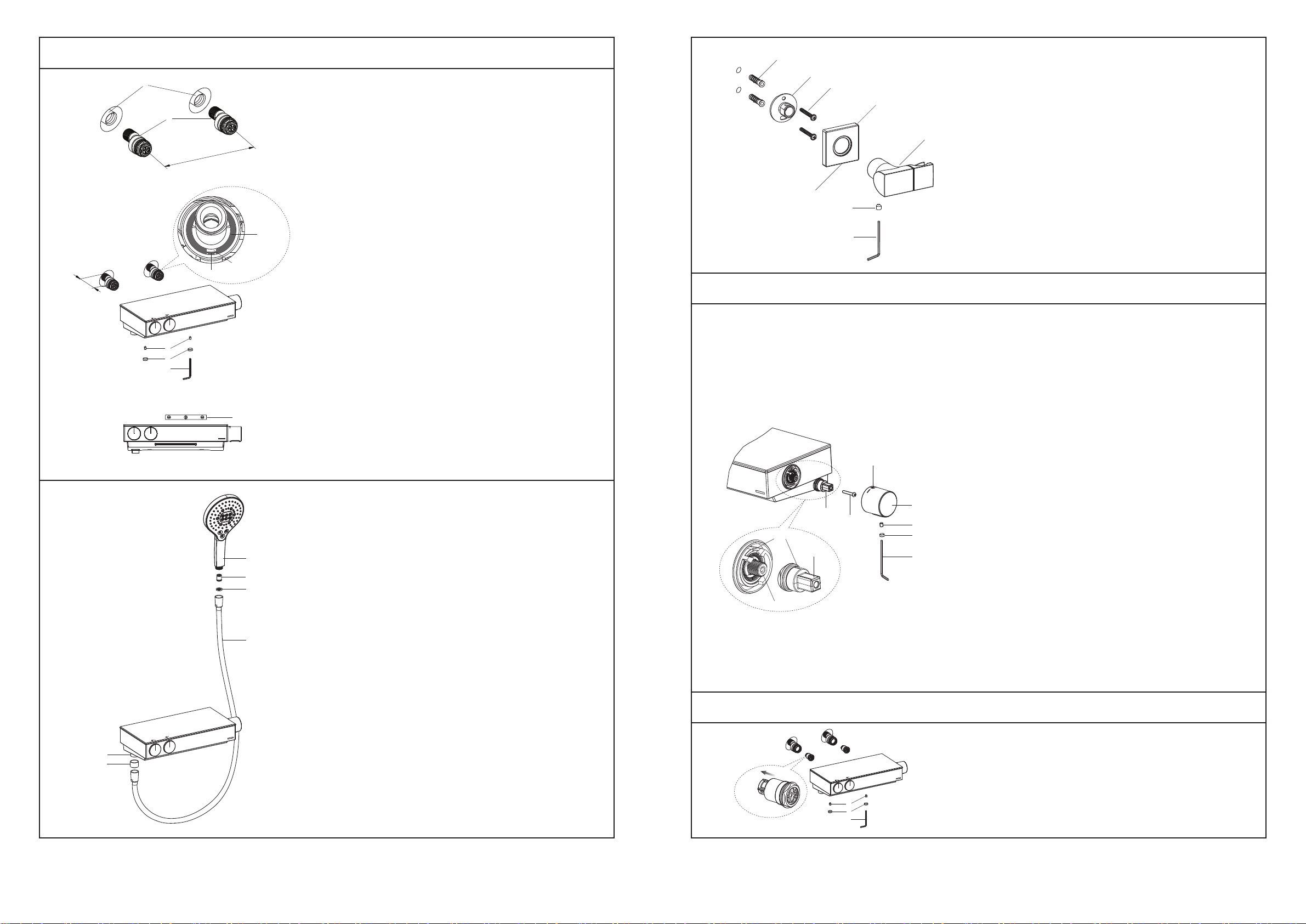
Install the Body
To perform installation, installer must provide G1/2″ female supply
fittings(1), spaced 150mm apart, horizontally and vertically to the
finished flat wall. Flush the water supply pipes thoroughly to
remove any debris.
NOTE: Apply water pressure test on water supply pipes before
installing the connectors(2).
Apply enough tape or suitable sealant on threads of connectors.
Install two connectors into the hot and cold supply pipes.
Adjust the center-to-center distance between the connectors to
150mm horizontally. They should extend 36~45mm beyond the
finished wall. NOTE: Rotate the C-rings with their openings
downward, and pull forward the C-rings to clamp the connectors.
Adjust two screws(4) with 3mm hex wrench(3). Install the faucet
body to the connectors until it is against the finished wall. Ensure
the upper surface is horizontal with the level(5).
Tighten two screws with 3mm hex wrench(The screws should
contact with the connectors through the C-rings’ openings).
Press the plugs(6) into the faucet.
Cold
Hot
1
2
150mm
5
36~45mm
4
3
6
Cold
Hot Opening
downward
Screw
C-ring
Drain notch
12
13
14
15
17
18
16
INSTALLATION
Install the Bracket
Determine a suitable location on the finished wall to install bracket.
Ensure it should avoid buried cables and pipes in the wall.
Mark the mounting holes of the base(12) on the wall according to
the dimension. Drill two holes in the finished wall, the holes should
match the anchors(13) and be vertical. Install the anchors. Tighten
the screws(14) to fix the base on the finished wall. NOTE: The
direction of the base is shown in the figure.
Loosen the screw(17) in the bracket(16) bottom with hex wrench
(15) until the bracket can be installed into the base. Slide the
escutcheon(18) onto the bracket. Apply a ring of plumbers putty or
other sealants around the underside of the escutcheon. Move the
bracket onto the base until it is against the finished wall and
confirm the drain notch and screw hole are pointed down. Tighten
the screw(17) with hex wrench to fix the bracket and escutcheon
on the finished wall. Remove any excess putty or sealant.
Clear the Filter
The filters protecting the faucet device may get obstructed and
reduce water flow. When this happens, turn off the water supply,
uninstall the shower column.
Take out the plugs(6). Unscrew two screws(4) with 3mm hex
wrench(3) to uninstall faucet. Take out the filters by hand. Clean
the filters by soaking them in warm vinegar. Reinstall in turn.
CARE AND MAINTENANCE
INSTALLATION CHECKOUT
Ensure that all connections are tight, the switch buttons are not
turned on. Turn on the water supply. Run water through the valve.
Check for leakage. Repair as needed.
Press the buttons separately. Check whether all connections and
water flow are well. Shut off the faucet.
Verification and Setting
Make sure that the water feeds of the faucet have reach their
highest temperature by letting the water run sufficiently. When the
number 37 on the temperature handle(19) is upward vertically,
the temperature of the water coming out of the faucet must be
within a range of 36ºC and 38ºC, as measured by a thermometer.
If this is not the case, the installer can adjust the setting. Proceed
with the setting as follows:
Remove the plug(21). Take out the screw(20) with 2.5mm hex
wrench(22) to uninstall the temperature handle(19). Remove the
screw(23) with a screwdriver. Remove the adapter spline(24).
With the faucet on “cold” normal water flow, slowly turn the
temperature selector(Always in the same direction) until water is
at 37ºC. If the temperature goes over 37ºC, go back to the “cold”
setting and set again. When the temperature is stabilized, do not
turn the cartridge spindle. Install the adapter spline. Ensure the
indicator line on the adapter spline align with the indicator line on
the stopper. Tighten the screw(23) with a screwdriver. Install the
temperature handle. Ensure the number 37 on the temperature
handle is upward vertically(After assembly, it could not be turned
counter-clockwise if not pushing the button). Tighten the screw
(20) with 2.5mm hex wrench. Insert the plug(21).
Number 37
22
19
20
21
23
24
Upward
horizontally
Spindle
Indicator line
4
3
6
Filter
Install the Handshower
Remove the protector cap from the connector(7).
Put the screen washer(8) into the shower hose(9). Connect the
handshower(10) and connector(7) with shower hose. Tighten all
the connectors. NOTE: Don’t over tighten.
Install the check valve(11) into the handshower if needed.
7
9
11
10
8
Protector cap