Kongskilde CPU User manual

CPU
Component Pickup Unit
Manual
Betriebsanleitung
Manuel de service
Podręcznik użytkownika
Brugsanvisning

2
GB
This user manual applies to the Kongskilde CPU (Com-
ponent Pickup Unit).
The target group for this manual are operators, (electri-
cal) installers as well as maintenance and service sta.
Description:
The Component Pickup Unit system is intended as an
extension of the CVL 700 unit itself, which makes it
possible to move small components, eg. from a con-
tainer in a warehouse and into a production line, in ap-
portioned quantities.
The CPU is designed to handle components ranging in
size from 10 to 50 mm in cross section, provided they
do not have a geometry that allows them to interlock, or
are particularly fragile. The CVL cannot handle liquids
or adhesive / damp components.
It is possible to control the performance of the con-
nected blower based on the current suction needs of
the CPU, by retrotting a MUC control - see section
"Accessories".
The system moves the components by evacating them
through a pipe / hose system. The pipe system consists
of steel pipes and exible hoses, with a diameter of
Ø100 mm.
The Component Pickup Unit system must not be used
in the food and pharmaceutical industry or in areas
where the ATEX directive is required.
The container containing the components to be moved
is emptied via a telescopic suction pipe which evacu-
ates the components up and through the suction string.
The telescopic suction pipe moves slowly through the
container, while swinging to the sides and back and
forth, removing layer after layer of components.
The container must measure a maximum of 1,2 x 1,2 x
1,8m. The container must not contain loose parts such
as cardboard discs or plastic foil that can be sucked to
the telescopic tube.
The air velocity in the suction string is measured and
regulated by regulation throttle EAR100-C. It is impor-
tant that the air velocity is kept constant and as low as
possible, to ensure that the components are not dam-
aged during transport.
The air velocity sucient to transport the components
of the piping system, is not large enough to absorb the
components from the container and into the telescopic
suction pipe. Therefore, the air velocity locally at the
"pickup" end of the suction pipe is increased. Boost air
velocity is measured and regulated by regulation throt-
tle EAR100-B.
The components are evacuated into the CVL via the
telescopic pipe and associated piping. At the top of the
CVL there is an ultrasonic sensor that detects when the
CVL is full of components (about 10 liters of compo-
nents), in combination wit the suction time setting in the
control unit. Then the top valve stops suction in the pipe
string, where after the bottom valve in the CVL opens
and empties the components. Top valve and bottom
valve in the CVL are driven by their own air cylinder.
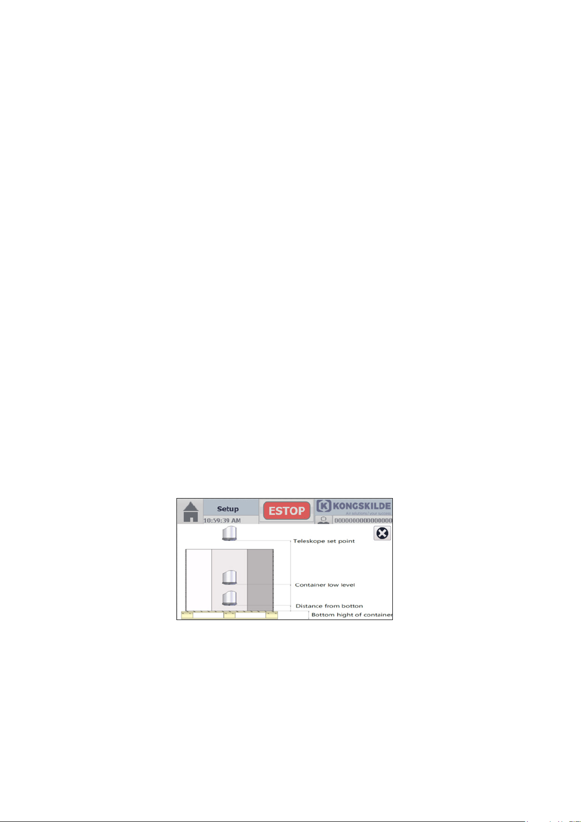
When the CVL is full and the air ow stops in the pipe
system, the telescopic suction pipe must be raised a
distance corresponding to the component height, to en-
sure that the components in the vertical part of the suc-
tion pipe fall out and do not block the suction pipe. After
the airow has restarted, the telescopic suction pipe is
lowered back to its original position and continues to
remove layer after layer of components.
The control of the CPU is connected to the control of
the CVL, to the control of the control valves (EAR 100),
and to the blower control. The system is integrated and
controlled from the CPU's control.
Access to the CPU control setting is done through the
operator panel in the column. The operator panel can
be logged in either as Operator or Tech, and only Tech
has rights to change settings.
See possibly section "Startup" with associated dia-
grams in the CVL manual, which describes the follow-
ing 3 installation modes:
Diagram C (Continuous process) - Should compo-
nents be drawn, typically from a magazine, with dis-
charge when a preset level in the CVL is reached, this
mode of operation is used. After discharge, the process
is repeated. This operating mode can be equipped with
start / stop contact, whereby the CVL can be stopped
when eg. the magazine is emptied.
Diagram D (Transport to external container with
level sensor) - Should components be drawn, typi-
cally from a magazine, with discharge in a container
equipped with full- and empty sensor, this operating
mode is used. The full- and empty sensor controls the
CVL, and ensures, that there are always components
in the container. This operating mode can be equipped
with start / stop contact at the CPU, whereby the CVL
can be stopped when eg. the magazine is empty.
It is optional if the blower should be started and
stopped by the control, or run constantly. If case the
blower should be controlled by the CVL control, the
blower must be connected, see diagram D.

3
Diagram E (Apportioned volume process) - Should
the components be moved, typically from a magazine,
with discharge in metered volume, this mode of opera-
tion is used. The volume is determined by a certain
number of discharges in combination with the level in
the CVL. After discharge, the process is repeated.
This operating mode can be equipped with start / stop
contact at the CPU, whereby the CVL can be stopped
when eg. the magazine is empty. Additionally, this mode
of operation shall be equipped with a reset switch, that
can be activated by replacing eg. cardboard boxes un-
der the CVL.
Emergency
stop
Level sensor for CVL
CVL Boost air string
Blower
Suction head
Coloumn
Telescopic
pipe
Footplate
Suction air string
CVL bottom
valve
Operators
panel
Regulation throt-
tle (EAR100-B) for
boost air
Regulation throttle
(EAR100-C) for
conveying air
CVL top valve
Sensor ring
Principle sketch with CVL installed longer from CPU
(2 separate controls for EAR100 throttles)
Main
switch

4
clutches can be adjusted, see section "Service and
maintenance".
The switch at the CPU control in the column can be dis-
connected in the event of service or repair.
Warning signs:
Warning signs with symbols without text are found on
the CVL. The meaning of the symbols is explained be-
low. If a warning label gets damaged, and is no longer
legible, it must be replaced. New labels are available in
the spare parts list.
Read the user manual carefully and
observe the warning texts in the
user manual and on the CVL.
Piping must not be removed while
the CVL is in operation. Wait until
compressed air and electricity has
been disconnected.
The CVL is equipped with a yellow mark around the
compressed air supply on the back console, as this
connection acts as an emergency stop.
Warning notes:
Avoid accidents by always following the safety instruc-
tions given in the user manual and on the safety signs
located on the CPU system.
The CPU may only be activated if the area around the
system is secured against access by uninstructed per-
sons.
The mounting of the unit must be as prescribed (see
section "Installation"), if not, stability is reduced, and
wear increased.
Ensure that all guards are intact and properly secured
during operation.
Always disconnect electricity and compressed air sup-
ply to the CPU/ CVL system before making any repairs,
maintenance or removal of blocked components. In
case the blockage is removed while air supply or elec-
tricity is connected, the cylinders can move, causing
serious injury.
Never put your hand into the unit´s inlet or outlet during
operation.
Make sure the service technician / operator has secure
access to repair and maintenance of the CVL. The
working area around the unit should be clear and trip
free when carrying out maintenance.
Make sure that there is adequate lighting when working
on the CVL unit.
In case of abnormal vibrations or noise, stop the unit
immediately and examine the cause. In case of doubt,
skilled assistance must be called in for repair and main-
tenance.
Do not operate the CPU without a container below the
telescopic pipe.
To avoid any personal contact with the moving valves,
pipes of minimum 850 mm length, (maximum Ø 200
mm) must be installed onto the inlet and outlet connec-
tions. These pipes must be installed with bolt clamps,
where tools are necessary for dismantling.
In case it is not possible to use minimum 850 mm
pipes, it must be ensured, that there within minimum
850 mm from the inlet and outlet, in all connections,
are used bolt clamps, where tools are necessary for
dismantling.
The reason for this is, that according to EU-directive
2006/42/EC (Machinery Directive), it is not allowed for
any unauthorized personnel to gain access to moving
/ dangerous parts. In case quick couplings are used,
unautorized personnel could dismantle the piping, and
gain access to moving parts.
The suction head of the Component Pickup Unit sys-
tem is equipped with slip clutches in both horizontal
directions of movement to prevent clamping between
the telescopic pipe / container and the column. These

5
Distance between bends
For maximum capacity, there should be a minimum
distance of 2 meters between changes in ow direction,
i.e. between each bend.
Insertion of bends
Never insert 2 bends straight after another, if they can
be replaced by one, as this can result in damage to
components and loss of capacity.
Assemblies and centring
All pipe joints must be tight and without any oset, as
these may damage the components!
When assembling pipes, bends and other material in-
tended for component transport, it is important to centre
the pipes as precisely as possible next to each other.
One cannot always expect the pipe to be centred by the
clamp alone. The quick clamp / bolt clamp is designed
so that it clamps the OK anges very hard to ensure
a tight assembly. This causes the friction between the
pipes to become so high that the clamp cannot centre
the pipes.
To check if the pipes are centred, one can check that
the distance between the clamp and the pipe is equal
on both sides of the clamp.
If you want a very tight joint, you can wrap the joint with
sealing tape before the clamp is applied.
Kongskilde recommends the use of the KCP 100R
pipe system, which ensures proper centering and
sealing of piping, which eventually reduces the risk
of component damage.
The 2 meter pipe is delivered with a loose ange on
the outlet side (not welded on), and can therefore be
used when adjusting the length, like a xed telescopic
pipe. The ange must be TIG welded, with concentricity
requirements as shown at the back in the manual, and
subsequently pickled.
The Component Pickup Unit system must be installed
indoors, at ambient temperature between 0° and 50° C.
Mounting:
The Component Pickup Unit system must be installed
on a stable, at concrete surface. The column must be
attached to the oor with expansion bolts, according
to the regulations from the bolt supplier. The enclosed
footplate must be mounted at the bottom of the column
as shown, to protect the column from damage caused
by truck collision during replacement of container, oc-
tabine or vacuum box.
It may also be necessary to mark with yellow / black
marking on the oor, or make other shielding. See sec-
tion "Warning notes".
Footplate
The piping and boost air / suction air hoses must be
securely supported to prevent breakage and leaks. The
suction hose should be controlled with a min. 300 mm
bending radius to prevent the components from block-
ing the hose.
Both the boost air- and conveying hose must be kept
as short as possible to reduce energy consumption, the
risk of static electricity, and component damage.
Kongskilde oers matching hoses and pipes, see sec-
tion "Accessories".
All pipelines and hoses must be installed before con-
necting electricity to avoid personal injury.
The CPU's control is delivered mounted in the upper
half of the CPU column upon delivery. If the control is
desired to be located in the lower half of the column,
the control can be hooked o the mounting tabs and
moved. To access the control, the CPU backplates
must be removed. The control is supplied with the re-
quired extra cable length.
Kongskilde recommends using stainless steel pipes for
component transport, as this will facilitate cleaning and
minimize contamination to the components. In addition,
it may be necessary to ground the installation and pos-
sibly install anti-static equipment to avoid static electric-
ity that can lead to component clumping and fouling.
See section "Electrical Installation".
External communication with e.g. Siemens PLC
If integration is made between the CPU control and
an external PLC control, the warranty on the control is
void.
90°
> 2 m
45°
45°

6
Lifting points
During installation, the CPU can be lifted with a strap
in the two holes at the shaft of the suction head and
around the shaft on the coloumn.
Accessories
Kongskilde oers the following accessories for the
Component Pickup Unit system - for more information,
please contact Kongskilde.
Conveying- and boost air hoses and Kongskilde
Component Piping KCP 100R (accessory)
Kongskilde oers conveying air hoses in 2,5 and 20
meters length, boost air hose in 2,5 meters length, as
well as various clamps and transitions.
In addition, piping in Ø100mm stainless steel (KPC
100R) is available for component transport. See back
of the manual.
External start / stop and telescopic pipe up / down
switch (accessory)
The CPU system can be equipped with an external
start / stop and telescopic pipe up / down switch. This
can be used if the operator panel is not mounted opti-
mally to the operation of the CPU system. The external
switch is equipped with a 10 meter cable that can be
extended to 100 meters, and should be connected to
the CPU control.
Blower control (Multi Unit Control)
It is possible to control the blower performance from
the CPU's current suction needs, by retrotting a MUC
control. The controller is mounted internally in a MultiAir
FC blower, and connected to the CPU's control with a
6-wire cable. Installation instructions and connection
are shown in the enclosed guide.
A MultiAir FC1250 blower will be able to drive up to 6
CPU´s.
Electrical connection:
The Component Pickup Unit system control is connect-
ed to L, N and ground via the supply cable (min. 3x1.5
mm2- not included), which is relieved at the bottom of
the column.
If an HPFI residual current relay is required on the pow-
er supply to the CPU, it must be a 300mA type B relay,
since the control contains built-in AC drives.
Blower control (Multi Unit Control)
The MUC controller is mounted internally in the MultiAir
FC blower, and connected as follows (see the enclosed
guide):
Start (hold switch) is connected to terminals 9 and 10.
Rpm Up are connected to terminals 11 and 12.
Rpm Down are connected to terminals 13 and 14.
Potential equalizing
In order to avoid the build-up of static electricity on
the components and reduce the possibility of static
discharges when the Component Pickup Unit system
is touched, it is important that the suction hose (Ø100
mm) ground conductor is properly connected to the
spigot at the top of the suction head and on the CVL.
Emergency stop
The Component Pickup Unit system pillar is equipped
with emergency stop, activated by pressure, and reset
by turning the emergency stop.
When planning the complete system, it should be deter-
mined whether any overall emergency stop contact is
necessary. If this is chosen, the general / local require-
ments for such contact must be met.

7
The emergency stop must disconnect the compressed
air supply and vent the cylinders on the CVL as this is
the only way to open both cylinders.
The requirements of the local Labour Inspectorate must
also be met.
Electronic Air Regulation (regulation throttle for
boost- and suction air)
The regulation throttle control box is connected to the
CPU's control with a CAT6 data cable. The data ca-
ble is plugged inside the EAR control box and guided
through the CPU column at the cable relief in the bot-
tom. Do not extend the cable as joints may impair reli-
ability.
External start / stop and telescopic pipe up / down
switch (accessory)
See section "Accessories".
Startup:
The parameters in the control unit can be adjusted to
ensure optimal integration of the complete transport
system. During balancing, it is recommended to pay
special attention to the air velocity of the system, as too
high a velocity may damage the components.
Before starting, check the following:
• that there are no foreign bodies in the Component
Pickup Unit, the CVL, the associated pipe system
or any suction hose
• that the compressed air supply is within the speci-
ed values
• that all connections to the control unit are properly
made
• that all parts are securely attached, including pipes
and any suction hose
• that the component output on the CVL is placed
min. 2,7 meters above oor level, to prevent ac-
cidental access to the bottom valve of the CVL,
which could otherwise result in personal injury
• that a container (with a max. width of 1.200mm,
a max. depth of 1.200mm and a max. height of
1.800mm) is located under the telescopic pipe. The
bottom of the container must be min. 150mm above
oor level
The Component Pickup Unit system´s operators
panel is operated as follows
In case ngertip operation problems occur, the eraser
at the end of a pencil could be used.
√
÷√
The operators panel has 2 levels of users; Operator
and Tech, with the following rights:
CPU management rights
Tech rights Operator rights
Component change
(program)
Change setting on
CPU, EAR and CVL
User Tech is password protected. The purpose of user
Tech is to set the CPU, EAR and CVL for optimal op-
eration.
User Operator can also be password protected, so it
is impossible to start or stop the CPU without being
logged into the operator panel. It is user Tech who sets
whether user Operator should be password protected.
If user Operator attempts to change settings, the
operator´s panel will display a popup box, in which user
Tech will need to log on.
NB - after 5 minutes of inactivity on the operator´s pan-
el, Tech is logged o. Therefore, Tech must log in again
before further setup can be done.
√

8
• The Main menu indicator shows which menu or sub menu the operator´s panel is in.
• The CVL icon provides access to readout of the settings for the CVL.
• Home moves from submenus etc. back to the main menu.
• Component select gives access to the menu, in which dierent components are selected, and according set-
tings for the component parameters.
• Settings allow access to change settings (Tech).
• Warnings show warnings.
• Stop interrupts the emptying with the CPU, and returns the telescopic pipe to starting position.
• Pause pauses the CPU / EAR / CVL, when the system is operating.
• Run starts CPU / EAR / CVL.
• Lower / raise telescope pipe lowers / raises the telescope pipe.
• Selected component displays the current component.
• Info shows additional information, which is "Low level" or "Prepare new container."
• User shows which user is logged onto the operator´s panel.
• The CPU icon provides access to readout of the settings for the CPU.
• The EAR icon provides access to readout of the settings for the air regulation throttles.
• Error shows any error condition.
Date and time
Home
Run
Info
Selected component
(program)
User
Info
Stop
Settings
Component se-
lect (program)
Pause
Main display
Main menu indication Error
Error
Error
CVL sub menu
EAR sub menu CPU sub menu
Lower telescopic pipe Raise telescopic pipe
Arrow, showing that tele
scopic pipe is ready to be
manually lowered

9
Component setting is changed by selecting a component number and conrm with Component settings con-
rm, where after the Component name eld is changed to show the current component.
The above are the only values that can be changed by User Operator. The following values for the component can
be changed individually, but only by user Tech. All times are given in milliseconds (ms) and all lengths in mm.
• Container low level setting adjusts when the info Low level appears, relative to the bottom of the container. A
distance of approx. 200mm is recommended.
• V1 Conveying speed setting adjusts the system suction velocity, in m/s. This value should be set as low as
possible to avoid damage to the components. In general, do not convey the components faster than what the
desired capacity allows and what is needed. As a starting point, one can hold a container of components up
to the telescopic pipe and check if the components are eectively sucked up. Subsequently, the suction veloc-
ity can be lowered until there is no longer eective suction, and then increased by e.g. 1- 2 m/s. In addition,
the blower speed should be adjusted according to the transport length and the components transported, etc.
Always adjust to the lowest required air velocity, to ensure as gentle transport as possible, and to reduce noise
and energy consumption. NB - Kongskilde oers a control (Multi Unit Control) that allows the CPU to control
the performance of e.g. a MultiAir FC blower,see section "Accessories".
• V2 Pickup speed setting adjusts the combination of boost air and suction air velocity. This value thus indi-
cates V1 suction air velocity + boost air velocity, and should basically be twice the V1 Conveying speed. If V2 is
set too high, the components are sucked to the bottom perforated part of the telescopic pipe.
Component select display
Component settings
Component name
Container low level setting
Component setup indication
Conyeying speed setting
Pickup speed setting
Distance from bottom
setting
Distance between
layers setting
CVL emptying time setting
No of CVL shakes setting
Telescope Setpoint setting
No of nal sweeps setting
Component settings save
Help pictogram
Component settings conrm

10
• Distance from bottom setting adjusts the height as the telescopic pipe moves upward after detecting the bot-
tom level of the container. Should be set to the average height of a component.
• Distance between layers adjusts the distance between each layer of components in the container, and should
be adjusted to the geometry of the components. The value is the distance the telescope pipe dives between
each layer of components.
• Number of nal sweeps setting adjusts the number of times the telescopic pipe swings back and forth after
reaching the bottom position. Should initially be set to 2, but can be increased if a satisfactory emptying of the
container is not achieved, after correct setting of V1, V2 and Distance from bottom. The number must be at
least 1.
• The telescope setpoint setting adjusts the height of the telescopic pipe above the oor and should at least
allow the container to be placed without hitting the telescope pipe. The distance is set by logging in as a Tech
user, going into the Component Pickup Unit settings display menu, lowering the telescopic pipe to an appropri-
ate height, and reading the value. The value can then be entered under the Telescope setpoint..
• Number of CVL shakes adjusts the number of movements in the bottom valve. This is done by rst opening
the cone in the bottom valve completely, and then closing approx. 4 cm, to shake o any hanging components.
The movement takes a few tenths of a second, and is done 3 seconds after opening the bottom valve. The
number of movements should be set as low as possible, but should still ensure that there are no components
hanging around the bottom valve cone.
• CVL emptying time setting adjusts the time from the CVL bottom valve opens until the bottom valve closes.
Should be set as low as possible, but not lower than all components manages to fall out of the bottom valve. If
not all components have fallen out, a rattle from the CVL will still appear and the time must be increased.
• Help provides access to this menu, which provides a graphical explanation of:
Telescope setpoint setting
Container low level setting
Distance from bottom setting

11
To change Settings, you must log in as user Tech. This is done by selecting the User rights setup eld, after which
you must log in as a user Tech. Default password for Tech is: 123.
The Settings menu is then available:
By selecting User rights setup, you can now select whether the Operator must log in with a password to be able to
operate the CPU. If the Operator does not have to log in for operation, the CPU is available to everyone.
User rights setup
Setup of local/remote start/
stop of CPU
Settings display
No. of EAR
Setup of local/remote up/
down of telescopic pipe
Enable / disable safety stop
Tech can also choose that
it requires Tech login to be
able to reset errors. This will
prevent the Operator from
resetting errors, and the
Operator is hereby forced to
call a technician with a Tech
login.
The user icon gives access
to the user passwords menu,
where Tech can assign pass-
words to the Operator.
Number of EAR
Number of
emptied
containers

12
In the menu for user passwords, Tech can assign and change passwords for Operator, as well as change password
for Tech:
In the User column, users can be created and removed, and in the Password column, passwords can be created
and corrected. In the Group column, the level of access can be assigned, and in the column Logo time, the time is
set in minutes after inactivity for logo. User PLC User is the default in the control and can not be deleted.
• Languages can be selected between English, German, French, Polish and Danish.
• Safety Stop can be used for external PLC communication, as a stop when, for example, a safety cage is
opened, and the safety circuit should be disconnected. If set to active, it does the following:
1. Stops the program
2. Stops the telescope in its current position
3. Stops CVL and connected blower after 10 seconds
• Electronic Air Regulation can be switched between single and double. If the CVL is placed at a longer dis-
tance from the CPU, it may be advantageous to use a smaller blower to generate boost air. The boost air regu-
lator throttle will be placed close to the CPU and therefore requires an additional control unit. In this case, sin-
gle (standing) control must be selected. If the CPU and CVL are placed close to each other, the blower gener-
ating suction air will usually also generate boost air, and both control throttles can therefore be controlled by the
same control unit. Here, double control is selected (the setting is given in advance when planning the project).
• Local / remote control start / stop is selected, depending on whether the CPU system should be started and
stopped at the CPU (on the operator´s panel in the column), or on the external start / stop switch that will nor-
mally be placed close to the container below telescopic pipe. If Local is selected, the control will only accept
input from the operator´s panel. If Remote is selected, the control will only accept input from the external start /
stop switch.
• Local / remote control up / down is selected, depending on whether the telescope pipe is to be raised and
lowered at the CPU (on the operator´s panel in the column), or on the external up / down switch that will nor-
mally be placed close to the container below the telescopic pipe. If Local is selected, the control will only accept
input from the operator´s panel. If Remote is selected, the control will only accept input from the external start /
stop switch.
• Empty containers show the number of containers that have been emptied since the last shutdown of the CPU.

13
CVL emptying time setting and CVL no. of shakes can be read in this menu, but only corrected under Compo-
nent select (see section "Component select").
V1 suction air speed and V2 pickup (boost air + suction air) speed can be read in this menu, but only corrected
under Component select (see section "Component select").
V1 suction air velocity (m/s)
V2 boost air + suc-
tion air velocity (m/s)
Electronic Air Regulation settings display
Component Vacuum Loader settings display
No. of shakes
CVL emptying time (ms)

14
On the arrow keys, the telescopic pipe can be operated respectively up and down as well as back and forth. Fur-
thermore, the pipe may be raised, e.g. in the event that the emptying process has been interrupted, or during set-
ting of the Telescope setpoint setting.
Telescope length indicates the current distance from underside of the CPU suction head to underside of the tel-
escopic pipe.
Component Pickup Unit settings display
Telescopic pipe
back/forth and
side to side
Telescopic pipe up
Telescopic pipe down
Telescopic pipe position

15
the CVL to check that all components have been re-
moved. This is done by releasing both air hoses and
removing the clamp ring and the lower part (with cylin-
der). Compressed air is recommended to remove any
jammed components.
An automatic circuit breaker is installed in the control to
protect the power supply to the PLC unit. If the circuit
breaker disconnects, the cause of this must be investi-
gated before reconnecting.
Technical data:
Voltage / frequency 230V - 50Hz
Weight, excl. accessories approx. 370kg
Ambient temperature 0° - 50° C
Max. container dimensions
(width x depth x height) 1.200 x 1.200 x
1.800mm
CPU dimensions - see back of manual.
Service and maintenance:
All service, maintenance and repair must be performed
by qualied or trained personnel.
Always turn o the power to the CPU before inspection,
and be sure to lock the main switch if desired, so that
the CPU cannot be started by mistake.
During cleaning or other service of the CVL, the com-
pressed air is switched o, and at least one sequence
is run, after which the power is switched o, e.g. on the
control main switch. The main switch can be locked if
desired.
The suction head contains couplings on the 2 gear mo-
tors, which control the forward / backward and side to
side movement of the telescope pipe.
The gear units on the gear motors are lled with syn-
thetic oil from the factory, which does not require re-
placement.
Pay attention to leaky oil seals.
If the telescopic pipe has diculty moving into the outer
positions, it may be necessary to tighten the couplings.
If the telescopic pipe pushes too strongly against the
sides of the container, it may be necessary to loosen
the couplings - the pipe must be able to be pushed
sideways by hand. In both cases, the adjustment re-
quires a special key as shown below.
Operation:
Start
• Container with components is placed under the
telescopic pipe. The foot plate of the CPU's column
can be used as a stop for the container.
• The blower / CVL and other associated machinery
are started, and the CPU main switch turned on.
• The CPU system starts and the Start icon changes
to green.
• When the yellow arrow appears on the operator´s
panel, the telescopic pipe can be lowered manu-
ally until the surface of the components. Be aware
of the height of the components in the box be-
fore emptying is initiated. If the suction end is not
lowered enough, the telescope swings beyond
the box edge! Advantageously, the surface of the
components can be levelled out before starting, to
increase the eciency of the emptying.
When emptying is complete, the telescopic pipe returns
to its original position and a new lled container can be
placed under the telescopic pipe, after which the pro-
cess can be repeated.
Pause
If desired, the CPU system can be paused, whereby
the Pause icon changes to blue. The system is restart-
ed by pressing Start.
Stop
If desired, the CPU system can be stopped, by press-
ing the Stop icon. The system is restarted by pressing
Start. At Start after Stop, the program starts all over
again.
The Low level icon appears as a reminder, that the tel-
escopic pipe is approaching the bottom of the container
(as a starting point approximately 200mm above the
bottom of the container).
The Prepare new container icon appears, as the tel-
escopic pipe begins emptying the last layer of compo-
nents in the container.
In case of clogging of the telescopic pipe, the pipe /
hose system must be dismantled and emptied / cleaned
manually. This can usually be done by removing the
suction hose at the top of the suction head and pulling
the blocked components up into a bucket or similar.
When switching from one type of component to anoth-
er, it is important to completely empty the CPU system.
This is usually done by running a pair of sequences
without components to empty the CVL's interior.
In some circumstances, it may be necessary to open

16
The couplings are adjusted as follows:
Gear in suction head
1. Turn o the power to the CPU and stop the blower.
2. Remove the left cover on the suction head (seen
from front).
3. Tighten the coupling by turning the coupling ring
clockwise.
4. Loosen the coupling by turning the coupling ring
anticlockwise.
5. Check the operation of the telescopic pipe.
6. Attach the cover on the suction head.
Gear in column
1. Turn o the power to the CPU and stop the blower.
2. Remove the upper back plate on the column.
3. Tighten the couplings by turning the coupling ring
clockwise.
4. Loosen the couplings by turning the coupling ring
anticlockwise.
5. Check the operation of the telescopic pipe.
6. Attach the back plate on the column.
The CPU does not contain any parts that require spe-
cial service or maintenance, but can be cleaned on
outer surfaces if needed. Furthermore, it may be nec-
essary to wipe the telescopic pipe, by fully extending it,
and wipe it with a suitable detergent.
The traction required for the CPU to slip in the clutch
is 10 kg when telescopic pipe is fully raised, and 6 kg
when it is fully lowered.
See also the "Operation" section.
Please also refer to the manual for the CVL and the
blower.

17
Troubleshooting:
Fault Cause Remedy
Emptying from con-
tainer interrupted or
reduced
Components blocked in telescopic
pipe or suction hose (or possibly
bottom valve / piping on CVL).
There will be a particular risk of
blockage, if components with a
larger cross section than approx.
50mm is handled
Switch o the CPU system with the emergency stop
on the side of the CPU column (to prevent CPU mo-
tors from overheating). Remove blocked components,
see section "Operation". Reset the emergency stop
and select "Conrm safety" on the operator panel.
If the telescopic pipe cannot be raised manually, it
may be a sign of a blocked pipe.
If needed, adjust the parameters on the operators
panel
Components have
diculty in falling out
of the CVL
Components are clumped inside
the unit due to improper compo-
nent design or static electricity
Replace components with more appropriate design /
nd another conveying method. Ensure correct earth
connection of the piping, suction hose and CPU/CVL,
see section "Electrical installation".
If needed, adjust the parameters on the operators
panel
Abnormal noise dur-
ing operation
Defective suction head Call service technician
Components are
crushed / damaged
by handling in the
CPU system
Inappropriate component design
or too high air velocity.
Too short opening time for bottom
valve
If needed, adjust the parameters on the operators
panel.
Increase CVL emptying time
Components get
wear marks and
smudging when
handling in the CPU
system
Too high air velocity, poor pipe
layout or incorrect material selec-
tion on piping to component han-
dling
Adjust the parameters on the operators panel.
Replace piping to stainless.
Check the pipe layout, see section "Installation"
Telescopic pipe mov-
ing erratic
Wire has run o wirewheel
Telescopic pipe binds due to dam-
age to the pipe, worn pipe bush-
ings or dirt on the pipe.
Telescopic pipes remain standing
with contact to the container side
as there is an error in the sensor
ring
Disconnect power to the CPU, remove the 4 white
covers on the suction head, and check if all wires sits
properly on the wheels. If not, lift the wires back on
the wheels and check the function.
Replace pipe or bushings / clean pipe.
Clean or replace sensor ring
Telescopic pipe is
not vertical in the
starting position at
startup
The default setting of the CPU
transducers has been changed
Correct the default setting, see the separate guide
below

18
CPU not operating
after pressing Start
Components blocked in telescopic
pipe or suction hose (or possibly
bottom valve / piping on CVL).
Level sensor in CVL or on con-
tainer under CVL (or other sensor
in the system) sends incorrect sig-
nal to CVL control.
Start / stop switch on CVL control
is in position Stop
Switch o the CPU system with the emergency stop
on the side of the CPU column (possibly to prevent
CPU motors from overheating). Remove blocked
components, see section "Operation". Reset the
emergency stop and select "Conrm safety" on the
operator panel.
If the telescopic pipes cannot be raised manually, it
may be a sign of a blocked pipe.
Check if sensors send the correct signal to the CVL
control, and adjust / replace the sensor if necessary.
Set switch to Start position
Telescopic tubes
constantly hit the
same side of the
container, and do not
move further
The CPU control depends on a
switch at the bottom of the tel-
escopic pipe, to detect the sides
of the container. Sometimes this
switch will not detect the side, and
then the telescopic pipe continues
its movement. This causes the tel-
escopic pipe to repeatedly hit the
side of the container. To mitigate
this, the CPU has a built-in timer
that detects whether the telescop-
ic pipe is stuck in the program,
and causes the telescopic pipe to
move in another direction.
If the telescopic pipe repeatedly hits the side for more
than 10 seconds, and it does not continue in another
direction, press the Stop button, after which the tel-
escopic pipe returns to its original position. Then Start
can be selected again.
If the CPU does not respond by pressing the Stop
button, the system is interrupted by the emergency
stop on the side of the CPU coloumn. With the emer-
gency stop activated, it is checked whether there are
mechanical faults, which can be rectied if neces-
sary. The emergency stop is then reset, and "Conrm
safety" is selected on the operator panel
Operator´s panel
shows "Telescope
safety switch on"
Pickup end of the telescopic pipe
briey rests on the components
in the container or on the upper
edge of the container.
The program will not stop
The error message disappears, after pressing "Ac-
knowledge" on the operator´s panel
Operator´s panel
shows "Telescope
minimum / maximum
position exceeded"
Pickup end of the telescope pipe
has reached the specied outer
limit
The error is deleted on the operator´s panel. If the
error occurs again, call service
Operator´s panel
shows "Conrm wire
not broken"
The telescopic pipe's wire broken
or dropped by the wire wheels
(the program will stop)
Telescopic pipe jammed onto the
components (the program will
stop)
Remove the side covers on the suction head and
check if the wires are properly seated. If not, reattach
wire or call for service
The error message disappears, after pressing "Ac-
knowledge" on the operator´s panel
Operator´s panel
shows "Acknowledge
motor fault"
Overheating or defect on the mo-
tors
Allow motors to cool down. If necessary, replace mo-
tors. The error message disappears, after pressing
"Acknowledge" on the operator´s panel

19
Operator´s panel
shows "Telescope lift
fault"
Pickup end of the telescopic pipe
rests on the components in the
container or on the upper edge
of the container. The fault is dis-
played after the CPU has tried to
suck up the obstacle 3 times, by
lifting and lowering the telescopic
pipe.
"Container lower level" is set too
low in relation to the height of the
container, and the telescopic pipe
hits the bottom of the container
before the pipe is in "Container
low level" zone
Check for obstructions at the end of the telescopic
pipe, such as a cardboard disc or plastic foil, and re-
move it. Select "Conrm safety" on the operator panel
and restart the process.
Change "Container low level" to a higher value
Operator´s panel
shows "EAR max ca-
pacity reached"
The EAR can not provide more
airow, as the damper is fully
open. This usually means that the
blower cannot supply enough air-
ow to the system.
Other causes can be an obstruc-
tion on the pipe system between
the damper and the CPU, which
prevents air from reaching the
EAR, or a large air leak between
the blower and the EAR
Check for leaks in the pipe system between blower
and EAR.
Check if there is an obstruction between CPU and
EAR, including the CPU telescopic pipe and associ-
ated hoses.
Check for obstructions and leaks elsewhere, and then
check if the blower can provide enough air output to
the system. This can possibly be done by keeping an
eye on how much the blower is loaded, in relation to
the desired air ow in the system
In case of doubt, contact a qualied service technician or Kongskilde service department.

20
Telescope pipe starting position adjustment
1. Disconnect the CPU power and clear the area be-
low the telescopic tube.
2. Manually push the telescopic pipe into starting po-
sition.
3. Remove the upper back cover of the coloumn to
gain access to the dial and transducers on the X-
axis.
4. Check if the dial is in the vertical position and cov-
ers the transducer halfway. If not, loosen the nut
and move the transducer in the oblong hole.
5. Check the operation of the telescopic pipe.
6. Attach the back plate on the column.
7. Remove right (seen from front) and rear cover on
the suction head, to access the dial and the trans-
ducers on the Y axis.
8. Check if the dial is in the horizontal position and
covers the transducer halfway. If not, loosen the nut
and move the transducer in the oblong hole.
9. Check the operation of the telescopic pipe.
10. Reinstall both covers on suction head.
Dial Transducer
Dial Transducer
Table of contents
Languages:
Other Kongskilde Industrial Equipment manuals
Popular Industrial Equipment manuals by other brands

PCB Piezotronics
PCB Piezotronics 1630-04C Installation and operating manual

vanEE
vanEE 100H Installer manual

Terri
Terri ATD Operator's manual

JETStream
JETStream J-FORCE JF6X15 Product instructions

Columbus McKinnon
Columbus McKinnon Yale HTP 1000 ATEX Translated Operating Instructions

Roland
Roland ZS-600 Replacement guide