manuals.online logo
Brands
  1. Home
  2. •
  3. Brands
  4. •
  5. Konica Minolta
  6. •
  7. Computer Hardware
  8. •
  9. Konica Minolta EK-501 User manual

Konica Minolta EK-501 User manual

Other Konica Minolta Computer Hardware manuals

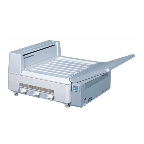
Konica Minolta SRX-101A User manual

Konica Minolta

Konica Minolta SRX-101A User manual

Konica Minolta SRX-101A User manual

Konica Minolta

Konica Minolta SRX-101A User manual

Popular Computer Hardware manuals by other brands

Toshiba TOSVERT VF-MB1/S15 IPE002Z Function manual

Toshiba

Toshiba TOSVERT VF-MB1/S15 IPE002Z Function manual

Shenzhen MEITRACK MVT380 user guide

Shenzhen

Shenzhen MEITRACK MVT380 user guide

TRENDnet TEW-601PC - SUPER G MIMO WRLS PC CARD user guide

TRENDnet

TRENDnet TEW-601PC - SUPER G MIMO WRLS PC CARD user guide

StarTech.com CF2IDE18 instruction manual

StarTech.com

StarTech.com CF2IDE18 instruction manual

Texas Instruments LMH0318 Programmer's guide

Texas Instruments

Texas Instruments LMH0318 Programmer's guide

Gateway 8510946 user guide

Gateway

Gateway 8510946 user guide

Devon IT TC2D Quick setup guide

Devon IT

Devon IT TC2D Quick setup guide

Krüger & Matz Air Shair2 owner's manual

Krüger & Matz

Krüger & Matz Air Shair2 owner's manual

Crystalio VPS-2300 quick guide

Crystalio

Crystalio VPS-2300 quick guide

MYiR FZ3 user manual

MYiR

MYiR FZ3 user manual

Protech Systems BC-K200 Quick reference guide

Protech Systems

Protech Systems BC-K200 Quick reference guide

Miranda DENSITE series DAP-1781 Guide to installation and operation

Miranda

Miranda DENSITE series DAP-1781 Guide to installation and operation

Sierra Wireless Sierra Wireless AirCard 890 quick start guide

Sierra Wireless

Sierra Wireless Sierra Wireless AirCard 890 quick start guide

Leadtek Killer Xeno Pro Quick installation guide

Leadtek

Leadtek Killer Xeno Pro Quick installation guide

Star Cooperation FlexTiny 3 Series Instructions for use

Star Cooperation

Star Cooperation FlexTiny 3 Series Instructions for use

Hotone Ampero user manual

Hotone

Hotone Ampero user manual

Connect Tech Xtreme/104-Express user manual

Connect Tech

Connect Tech Xtreme/104-Express user manual

Yealink WF50 user guide

Yealink

Yealink WF50 user guide

manuals.online logo
manuals.online logoBrands
  • About & Mission
  • Contact us
  • Privacy Policy
  • Terms and Conditions

Copyright 2025 Manuals.Online. All Rights Reserved.

4036-7773-02 Printed in Japan
INSTALLATION MANUAL
EK-501
for Product Code 4036
Local Interface Kit
NOTES
•Before installing, be sure to unplug the power cord of the machine.
•Keep all packing materials out of the reach of children.
4036-7773-02E.fm 0 ページ 2004年2月12日 木曜日 午前9時20分
EK-501
– 1 –
■Unpacking the Local Interface Kit
Check that the following accessories are available in the box.
■Installing the Local Interface Kit
1 Local Interface Board .............................................................................1
2 Spacer Screw .........................................................................................3
3 Screw .....................................................................................................2
4 Installation Manual (this manual) ...........................................................1
1 2 3 4
4036U014AA 4036U015AA 9654
1. Turn off the machine and unplug the power
cord from the machine.
2. Remove the lower rear cover (seven
screws).
4348U106AA
3. Remove the upper rear cover (five screws).
4036U001AA
4. Open the right door, and then remove the
right rear cover (four screws).
4036U002AB
5. Remove the shield cover (twelve screws).
4036U003AB
4036-7773-02E.fm 1ページ 2004年2月12日 木曜日 午前9時20分
EK-501
– 2 –
6. Remove the ornamental cover from control
board cover (one screw).
4036U016AA Ornamental Cover
7. Remove screws and disconnect the
connector. Then, remove the control board
cover (nine screws).
4036U017AB
8. Remove the three screw fixing the control
board assy.
4036U018AA
9. Install three Spacer Screws furnished with
the kit to the control board assy.
4036U019AA
10. Connect the local interface board connector
to the PJ10 of the control board assy.
11. Secure the local interface board in position
using three screws which has been removed
in step 8.
4036U020AA
12. Reinstall the control board cover (nine
screws).
13. Secure the connector in position using two
screws furnished with the kit.
NOTE
When tightening the screws, make sure
that the locks of the connector are raised
as shown on the left.
4036U021AA
14. Connect the connector which has been
disconnected in step 7.
15. Reinstall the shield cover (twelve screws).
16. Reinstall the right rear cover (four screws).
17. Reinstall the upper rear cover (five screws).
18. Reinstall the lower rear cover (seven
screws).
4036-7773-02E.fm 2 ページ 2004年2月12日 木曜日 午前9時20分