Konica Minolta SRX-101A User manual

MODEL SRX-101A
SERVICE MANUAL
No. 26-2, Nishishinjuku 1-chome, Shinjuku-ku, Tokyo 163-0512, Japan
4TH EDITION MAY 2004
CODE NO. 1051
CODE NO. 1052
CODE NO. 1069
StockCheck.com

StockCheck.com

SERVICE MANUAL
SRX-101A Medical Film Processor
Contents
■Precautions........................................................................................................................ 1
■Tools and Instrument ........................................................................................................ 1
■Caution Labels................................................................................................................... 2
1. Specifications.................................................................................................................... 4
2. Dimensions........................................................................................................................ 5
3. Name of Parts .................................................................................................................... 6
4. Time Chart.......................................................................................................................... 21
5. Troubleshooting................................................................................................................. 22
6. CPU Board DIP Switches.................................................................................................. 53
7. Checking Circuit Boards, Sensors and Electrical Loads............................................... 69
8. Electrical Components Diagram...................................................................................... 76
9. Wiring Diagram of Main Unit ............................................................................................ 78
10. Circuit Board Diagram....................................................................................................... 81
11. Disassembly and Reassembly ......................................................................................... 97
12. Upgradeing the Program Version..................................................................................... 103
13. Pre-Installation Instructions............................................................................................. 108
14. Installation Instructions and Precautions....................................................................... 114
15. Changing Processing Conditions.................................................................................... 126
16. SRX-101A Customer Presentation Guide........................................................................ 127
17. SRX-101A Light Shield Installation Manual .................................................................... 133
18. Installation Procedure....................................................................................................... 135
This Service Manual is prepared for the service of SRX-101A classified as follows;
Product Code Serial No.
1051 : #20001 ~
1052 : #20001 ~
1069 : #20001 ~
StockCheck.com

StockCheck.com

PRECAUTIONS
1SERVICE MANUAL
■ PRECAUTIONS
Before shipment from the factory, the procedure has already been inspected according to local
safety regulations.
However, the following precautions must be taken when servicing this equipment.
(1) Before servicing, disconnect the automatic processor's power plug from is AC outlet.
If it is absolutely necessary to repair the processor while the power is on, be sure to take
precautions to avoid electrical shock and keep your fingers away from rollers, gears and other
moving parts.
(2) Use only the types of fuses specified in this manual.
(3) Use only the replacement parts specified in this manual.
(4) When unplugging connectors, disconnect them at the socket. Do not pull on the wire bundle.
(5) When carrying or shipping circuit boards, place them in static-proof bags, or containers made of
conductive material to prevent damage from static electricity.
(6) Do not touch the wiring patterns, connector contacts or solder on the circuit boards.
(7) Take care to prevent washers, bolts or other metal objects from failing into the machine and
causing short circuit or damage to gears. etc.
(8) Remodeling of processor components or systems which is not described in this operation
manual is forbidden.
(9) After repairs, make sure all parts and wiring have been correctly replaced and reconnected.
(10)
Be careful not to tighten the tapping screws too much.
■ TOOLS AND INSTRUMENT
In addition to your standard service-use tool kit. the following special tools and equipment will be
necessary.
(1) Push-pull Gauge (Max. 500g)
StockCheck.com

2SERVICE MANUAL
CAUTION LABEL
●Caution labels imply the degree of the risk which may arise from incorrect use of this
product.
●There are 3 degrees of caution labels, and each is used depending on the level of risk
and damage caused by incorrect use and mishandling.
DANGER : If failed to avoid the risk, this implies the imminent danger level which may
lead to serious injury including a loss of life.
WARNING : If failed to avoid the risk, this implies the danger level which may lead to
serious injury including a loss of life.
CAUTION : If failed to avoid the risk, this implies the danger level which may lead to
moderate damage or light injury. Also it is used when a physical damage
alone is expected.
Risk of the damage
High Low
Loss of life or
DANGER WARNING
Bodily injury
serious injury
(and damage to property)
(Damage is serious)
Moderate damage or WARNING
light injury or CAUTION
(Damage is light) CAUTION
Damage to property only CAUTION
Should this manual become not readable due to any reason,
replace it with a new one which is available at charged basis.
1. EXPLANATION OF CAUTION LABELS
■ CAUTION LABELS
StockCheck.com

3SERVICE MANUAL
(1)
2. WARNING LABELS AND THEIR LOCATIONS
UL
CE
(2)
(2)
(1)
▲
StockCheck.com

4SERVICE MANUAL
SPECIFICATIONS
Model name : SRX-101A
Film transport method : Continuous roller transport.
Film type and sizes : Sheet film, 10 x 10 cm~ 35 x 43 cm(14 x 17 inch) sizes.
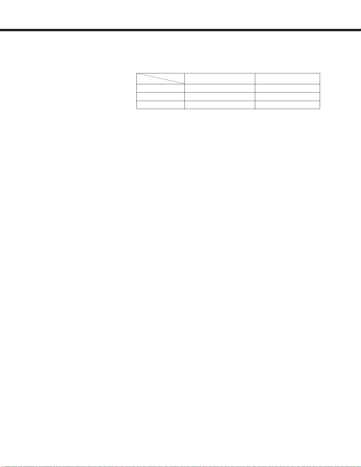
Processing capacity :
Process cycle switching : Available by a service engineer.
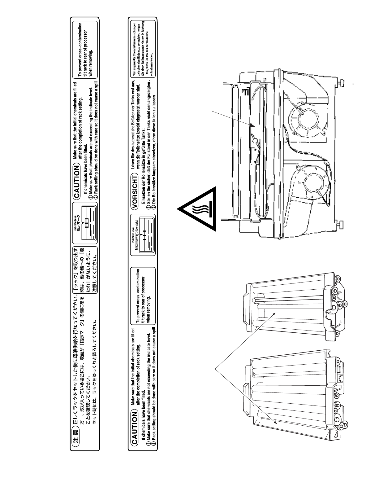
Processing solution volumes : DEV tank : 3.9 liters(1.03 gallons)
FIX tank : 1.8 liters(0.47 gallons)
WASH tank : 1.4 liters(0.37 gallons)
Temperature control : Processing solution temperature;
Controlled by the temperature control tank, with the thermistor monitoring,
and with the heater heating.
Drying temperature;
Controlled automatically according to a fixed temperature setting.
Replenishing system : Replenishing volume for the film sheet is calculated exchanging with
24 x 30 cm or 10 x12 inch film
Circulation system : Continuous pumping of developer and fixer solutions.
Wash water : Ordinary tap water 5 ~ 30:(41 ~ 86<)
Water pressure 29.4 ~ 784 kPa(0.3 ~ 8kgf/cm
2
, 98 ~ 112psi)
Water supply : 0.8 liters(0.22 gallons)/min.
Standby functions : 10min./30min./Continuous operation. (Selectable by a service engineer)
Power source : AC 115/120V, single phase, 12A, 60 Hz.
AC 200/230/240V, single phase, 6A, 50Hz.
Dimensions(W x D x H) : 610 x 680(900 incl. feed table) x 453 mm
24.0 x 26.8(35.4 incl. feed table) x 17.8 inch.
Weight : CE 40kg (47kg with processing tank full)
UL 37kg (44kg with processing tank full)
81 lb (97 lb with processing tank full)
Certification : Conforms to UL, FDA, TÜV
Applied standard : FCC/CE
Heat generation : Approx.3135kJ/hr max.
Noise level : Approx.55dB(A) max.
Operating condition : 15 ~ 30:(59 ~ 86<), 30 ~ 75%RH(no condensation)
Storage and transport condition : -20 ~ 60:(--4 ~ 140<), 20 ~ 95%RH(no condensation)
Accessories : Measuring cup, Funnel, Installation parts kit, Replacement parts kit,
Replenisher tanks, and Operation manual.
Optional equipment : Light shield panel, Stand, Splash guard,
DEV Temp. Control kit.(CE only)
Remarks for CE Version : This equipment is the CE marking product conformable to the directive
93/42/EEC (MDD) and the harmonized standard EN60601-1, EN60601-1-2.
Medical film processor SRX-101A is produced in factories that have been
certified to be in compliance with the ISO13485:2001, IS09001:2000 quality
control standards.
Remarks for UL Version : Medical film processor SRX-101A is produced in factories that have been
certified to be in compliance with the IS09001 : 2000, and IS013485 : 2001
quality control standards, as well as with the medical device directive FDA
Premarket Notification 510(k) and GMP.
*The above specifications are subject to change without prior notice.
Size
Cycle
24 x 30 cm or 10 x 12 inch 35 x 43 cm(14 x 17 inch)
90sec. 75 60
120sec. 70 55
180sec. 55 40
(sheets/hr)
1. Specifications
StockCheck.com

DIMENSIONS
5SERVICE MANUAL
2. Dimensions
2-1. Main Unit and Support
2-2. 25 Liter Replenisher Tank (Standard Equipment)
900 610
500
600
611
676
500
453
750
430
600
623
Main Unit
Support (Optional)
StockCheck.com

6SERVICE MANUAL
NAME OF PARTS
3-2. Main Unit (Left Side View)
Power Breaker
Power Cord
Wash Water Drainage Hose
(larger diameter than other hoses)
Fixer Drainage Hose
(red) Fixer Supply Hose
(red)
Binding Tape
Electrical Components
Housing
Developer Supply Hose
(yellow)
Developer Drainage Hose
(yellow)
Overflow Drainage Hose
Right Side Panel
Film Exit
Top Cover
Level Adjustable Leg
Control Panel
Feed Tray
Feed Tray Cover
Fixer Drainage Valve Developer Drainage Valve
Water Supply Hose
Wash Water Drainage Valve
Left Side Panel
3-1. Main Unit (Front View)
3. Name of Parts
StockCheck.com

NAME OF PARTS
7SERVICE MANUAL
3-4. Control Panel
3-3. Main Unit (Rear View)
RUN
READY
RUN
Drier Section Cover
Back Panel
"RUN" Lamp
Lights up when the [RUN] SW is
pressed. Will automatically go out if
no film has been inserted for 8 hours
after the "READY" LAMP lamp went
on. Will light up again when the
[RUN] SW is pressed.
"READY" Lamp
Lights up when the temperatures of
the processing chemicals and heater
are at their preset values. Film may
be inserted for processing whenever
this lamp is on.
[Repl.](Replenishment) SW
Press and hold down this switch for
about 5 seconds to begin the supply
of processing chemicals to the tanks
at a rate of 3Pper second. During
replenishment, "READY" LAMP lamp
will change to flashing.
[RUN] SW
Press this switch to start and stop
film processing.
RUN SW Lamp
Indicates that the SRX-101A is
electrically powered.
StockCheck.com

8SERVICE MANUAL
NAME OF PARTS
Different ON-OFF patterns shown by the "RUN" and "READY" lamps on the control panel indicate different operating
conditions. The following is a listing of all the possibilities and the conditions they indicate.
"RUN" and "READY" LAMP Lamps ON-OFF Patterns
OFF
OFF
ON
ON
ON
OFF
OFF
Flashing(Pattern 1)
OFF
Flashing(Pattern 2)
ON
Flashing(Pattern 1)
OFF
Flashing(Pattern 1)
ON
RUN
READY
RUN
READY
RUN
READY
RUN
READY
RUN
READY
RUN
READY
RUN
READY
RUN
READY
Flashing(Pattern 2)
ON-OFF Pattern
Operating Condition
LED Pattern
All operations shut down
Normal operation
(Operating temperature OK)
Normal operation
(Operating temperature LOW)
Preparing for supplying
chemical solutions
([Repl.] SW ON for 5 sec.)
Supplying chemical
solutions
Manual replenishment
Drive motor error
Dry Temperature error
Pattern 1
0.5
0.5
ON OFF
Pattern 2
0.7
0.10.1
0.1
Pattern 2
0.7
0.10.1
0.1
Pattern 1
0.5
0.5
ON OFF
Pattern 1
0.5
0.5
ON OFF
RUN
READY
RUN
READY
Flashing(Pattern 1)
ON
Flashing(Pattern 1)
ON
DEV Temperature error
Film Sensor error
Pattern 1
0.5
0.5
ON OFF
Pattern 1
0.5
0.5
ON OFF
Buzzer Sound Pattern
0.5
0.5
ON OFF
1.0
0.1 0.1
0.1 0.1 0.1
0.1 0.1
1.0
0.1 0.1
0.1 0.1
0.1
1.0
0.1 1.0
0.1
StockCheck.com

NAME OF PARTS
9SERVICE MANUAL
3-5. Main Unit (Top View)
Wash Water Tank
Drive Shaft
Fixer Tank
Developer Tank
Rack Handles Rack Handles
Developing Rack
Starter Solution Inlet
Fix/Wash Rack
StockCheck.com

10 SERVICE MANUAL
NAME OF PARTS
Dry Rack
Drying Heater Unit
Duct Nozzle
Overheat Switch
Recycle Duct Dry Fan Recycle Duct
Dry Sensor Unit
3-6. Drying Unit
StockCheck.com

NAME OF PARTS
11SERVICE MANUAL
Springs Type Parts No.
L=74 1361013050
L=80 103014027A
Worm Gear Parts No.
Right 1050-13003A
Left 1050-13004A
3-7. Film Transport
1) Rollers
(1) Components Diagram
StockCheck.com

12 SERVICE MANUAL
NAME OF PARTS
(2) Roller Component Listing
NOTE :
In the processing tanks, the "upper" rollers are vertically higher rollers in the solution. In the
drying unit, the "upper" rollers are the rollers closer to the feed tray side of the main unit. the
rollers on the other side are the "lower" rollers.
(3) Capability
The SRX-101A is capable of processing film ranging in size from 10x10 cm to 35x43 cm
(14x17 inch).
The feed tray has an insertion slot that will feed film up to 17" in width.
Processing
Unit
DEV
FIX
WASH
DRY
Upper roller material
Silicon (H)
Bakelite (A)
EPDM (D)
Bakelite (A)
Bakelite (B)
Bakelite (B)
Bakelite (A)
Wipe-down (E)
Silicon (H)
Wipe-down (E)
Bakelite (A)
Bakelite (A)
Lower roller material
Bakelite (A)
Bakelite (A)
Bakelite (A)
Bakelite(lead surface) (C)
Bakelite (A)
Bakelite (B)
Bakelite (A)
Wipe-down (F)
Wipe-down (E)
Silicon (H)
Bakelite (A)
Bakelite (A)
Roller No.
[1]
[2]
[3]
[4]
[5]
[6]
[7]
[8]
[9]
[10]
[11]
[12]
Spring
length
74mm
80mm
74mm
80mm
74mm
74mm
74mm
74mm
74mm
74mm
74mm
74mm
Spring pressure
in grams
410 ~ 480
110 ~ 170
410 ~ 520
180 ~ 270
490 ~ 530
450 ~ 530
330 ~ 530
610 ~ 860
590 ~ 720
470 ~ 620
410 ~ 520
460 ~ 560
StockCheck.com

NAME OF PARTS
13SERVICE MANUAL
2) Drive Mechanism
(1) Components Diagram
(2) Capability
Timing Belt
Timing Belt
Drive Motor
Gear Type Symbol Parts No. Name Module No. of Teeth Note
Worm Gear A13003A Worm Gear (Right) 1.5 3 CW
B13004A Worm Gear (Left) 1.5 3 CCW
Worm Gear C13007B Worm Wheel (Right) 1.5 18 CW
D13008B Worm Wheel (Left) 1.5 18 CCW
Idler Gear E13002A Idler Gear (Small) 1.5 16
F13011A Idler Gear (Large) 1.5 26
Roller Gear G13001B Gear 1.5 12
H13010B Gear 1.5 12
Processing Cycle Time (Sec.) 90 120 180
Transporting Speed (mm/min) 460 350 236
Capability 24x30cm (10x12 inch) 75 70 55
(sheets/hour) 35x43cm (14x17 inch) 60 55 40
StockCheck.com

14 SERVICE MANUAL
NAME OF PARTS
3) Adjusting the Drive Timing Belt
(1)Remove the Top Cover, the Right Side Panel and the Back Panel.
(2)Test the tension in the timing belt with a push-pull gauge at a point half way between the main
drive shaft pulley and the drive motor pulley. Adjust the belt tension by loosing the drive motor
and moving it up or down. Proper timing belt tension is in a range between loads of 75 and
125 grams with approximately 2 mm of slack in the belt. Refer to the diagram below.
(3)Wind the rotor located on the back side of the motor mounting 3 times, then check the belt
tension once more to make sure that it is still in a range between loads of 75 and 125 grams
with approximately 2mm of slack in the belt.
(4)Repeat the same step of (3) eight times. If the tension falls in the above range eight times in a
row, the adjustment has been successfully completed. If even one test result falls that range,
the whole adjustment procedure must be repeated from the beginning.
Main Drive Shaft
Timing Belt
Drive Motor
Drive Motor Pulley
2mm
75~
125g
From the rear side of the processor
StockCheck.com

NAME OF PARTS
15SERVICE MANUAL
Temperature
Control Tank
Developer
Drainage Valve
Electromagnetic
Valve
Fixer Drainage
Valve
Wash Water
Drainage Valve
Fixer Circulation Pump
Developer Supply Unit
Fixer Supply Unit Developer Circulation Pump
3-8. Solution Supply and Drainage Unit
StockCheck.com
Other manuals for SRX-101A
2
Table of contents
Other Konica Minolta Computer Hardware manuals
Popular Computer Hardware manuals by other brands

Alesis
Alesis NanoCompressor Reference manual

ADLINK Technology
ADLINK Technology NuIPC cPCI-3500A Series user guide

ADLINK Technology
ADLINK Technology MXM-AXe user guide

MicroSys
MicroSys miriac MPX-LS1043A2 user manual

Infineon Technologies
Infineon Technologies CYTVII-B-E-BB quick start guide

silicom
silicom TimeSync STS2 Hardware installation guide