manuals.online logo
Brands
  1. Home
  2. •
  3. Brands
  4. •
  5. Konica Minolta
  6. •
  7. Printer
  8. •
  9. Konica Minolta Copier 2223 User manual

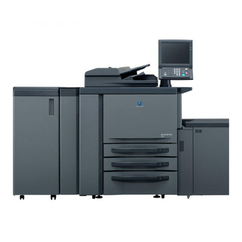
Konica Minolta Copier 2223 User manual

OPTION
1. MAINBODY
PRODUCT SPECIFICATIONS .................................... 1-1
[1] Type ................................................................. 1-1
[2] Function ........................................................... 1-1
[3] Particulars of Machine...................................... 1-1
[4] Maintenance..................................................... 1-1
[5] Operating Environment .................................... 1-1
CENTER CROSS-SECTION....................................... 1-2
DRIVE SYSTEM SECTION......................................... 1-3
[1] Main Drive ........................................................ 1-3
[2] ADU Nip Roller Drive ....................................... 1-3
MAIN DRIVE SECTION............................................... 1-4
[1] Construction ..................................................... 1-4
[2] Mechanism....................................................... 1-4
[3] Disassembly and Assembly ............................. 1-5
[5] Paper Exit Gate Control ................................. 1-13
[6] Paper Feed Control........................................ 1-13
ADU NIP ROLLER DRIVE SECTION........................ 1-14
[1] Construction ................................................... 1-14
[2] Mechanism..................................................... 1-14
[3] Disassembly and Reassembly ....................... 1-16
[4] ADU Control ................................................... 1-21
LCT/PFU SECTION................................................... 1-23
[1] Construction ................................................... 1-23
[2] Mechanism..................................................... 1-23
[3] Disassembly and Reassembly ....................... 1-24
[4] LCT Lift Control .............................................. 1-28
2. DIAGRAMS
DB-307/107/607 ELECTRICAL PARTS LAYOUT
DRAWING ................................................................... 2-1
DB-307/107/607 CONNECTOR LAYOUT DRAWING. 2-3
DB-307/107/607 OVERALL WIRING DIAGRAM......... 2-5
DRIVE BOARD CIRCUIT DIAGRAM .......................... 2-6
DB-307/107 ADU FACE SIDE TIMING CHART
(A4, 2 sheets stacking) ............................................ 2-7
DB-307/107 ADU BACK SIDETIMING CHART
(A4, 2 sheets Re-feed)............................................. 2-8
CONTENTS
1-1
PRODUCT SPECIFICATIONS
[1] Type
Type: ADU None-stack type (paper conveyance/
changeover with nip rollers)
LCT Tray paper feed (front loading)
PFU Tray paper feed (front loading)
[2] Function
Paper size: ADU A3 to A5R
11×17 to 8.5×11R
LCT A4/A4R/B5/B5R/A5R
8.5×11/8.5×11R
PFU A4/A4R/B5/B5R/A5R
8.5×11/8.5×11R
Kind of paper: 60 g/m2to 90 g/m2fine quality paper
ADU capacity: 10 sheets max. (80g/m2)
Tray capacity: LCT 1000 sheets max. (80g/m2)
PFU 250 sheets max. (80g/m2)
[3] Particulars of Machine
Power requirements: DC24V/5V (supplied from the
main body)
Max. power consumption: 50 VA
Weight: Approx. 36 kg
Machine dimensions:
[4] Maintenance
Maintenance: Same as the main unit
Service life: Same as the main unit
[5] Operating Environment
Temperature: 10˚C to 33˚C
Humidity: 20% to 80% RH
These specifications are subject to change without notice.
(mm)
PRODUCT SPECIFICATIONS
565 520
470
1-2
CENTER CROSS-SECTION
ADU nip rollers
from main body to main body
ADU section
ADU stacker section
Changeover
conveyance section
LCT paper feed roller
Conveyance rollers
(Upper)
LCT tray
PFU paper
feed roller
PFU tray
Conveyance rollers
(Middle)
Conveyance rollers
(Lower)
DB-307 CENTER CROSS-SECTION
1-3
ADU changeover gate
Nip roller elevating cam
ADU changeover
solenoid (SD101)
Changeover/
clutch lever
ADU drive motor (M101)
Nip rollers (16)
Changeover conveyance roller 1 Drive gear
of main body
(ADU Conveyance Drive)
Drive gear of main body
(LCT/PFU Conveyance Drive)
Conveyance roller (Lower)
PFU paper
feed roller
Conveyance roller
(Middle)
Conveyance roller
(Upper)
LCT paper feed roller
Changeover
conveyance roller 3
Changeover
conveyance roller 2
[1] Main Drive
[2] ADU Nip Roller Drive
DRIVE SYSTEM SECTION
DB-307 DRIVE SYSTEM SECTION
1-4
Changeover conveyance roller 1 Drive gear
of main body
(ADU Conveyance Drive)
Drive gear of main body
(LCT/PFU Conveyance Drive)
Conveyance roller (Lower)
PFU paper
feed roller
Conveyance roller
(Middle)
Conveyance roller
(Upper)
LCT paper feed roller
Changeover
conveyance roller 3
Changeover
conveyance roller 2
[1] Construction
MAIN DRIVE SECTION
[2] Mechanism
Mechanism Method
LCT paper feed drive Gear driven by main motor/
gear drive
PFU paper feed drive Gear driven by main motor/
gear drive
Paper route change Paper exit change gate
ADU changeover roller drive Gear driven by Main motor/
gear drive
∗1. Paper route change
The route of a paper from the fuser section is changed by
the paper exit change cover gate: one path is to cause the
paper to come out of the exit, and the other is to cause the
paper to go to the ADU reversal section.
In case of one-sided copying mode, paper goes to the exit,
and in case of two-sided copying mode, it goes to the ADU
reversal section.
Theexit paperchangeover gateis controlledby turningon/
off the ADU gate solenoid (SD13).
MAIN DRIVE SECTION
∗1
Paper exit change gate ADU gate solenoid (SD103)
To ADU Reversal Section
Paper Exit
1-5
PapersfedtotheADUareheldbytheniprollersandstored
in the stack section up to 10 sheets.
ADU
nip rollers
ADU
stack section
The paper in the stack section is fed to the changeover
conveyancesectionby meansofreverse rotationofthe nip
roller. The paper is entered into the normal conveyance
route in the main body, then copied on the back side and
finally delivered to the exit tray.
ADU stack section
ADU nip rollers
Changeover
conveyance
section
MAIN DRIVE SECTION
[3] Disassembly and Assembly
Caution: Disconnectthepowercableplugfromthewall
outlet.
1. Removing/reinstalling the ADU Conveyance Unit
(Lower)
a. Procedure
(1) Open the upper main body.
(2) Remove the four set screws, then remove the exit tray
with the mounting plate.
CAUTION:If the sorter is already installed, remove the sorter
first from the main body.
I
(3) Remove the set screw, then remove the fixing front
cover.
Set screwFixing Front cover
Set screws
Exit tray Exit tray
mounting plate
1-6
Set screws
ADU Guide unit
(4) Remove the four set screws, then remove the ADU
guide unit.
(5) Remove the set screw, then remove the ADU Convey-
ance unit (Lower).
Set screw
ADU conveyance
unit (Lower)
(6) Reinstall the guide in the reverse order of removal, but
the following should be carefully executed.
Note: 1. MakesuretheholesintheADUgatesolenoid(SD103)
are aligned with the two locating pins.
Pins/holes
ADU gate solenoid (SD103)
ADU Conveyance Unit (Lower)
Holes Pins
2. Align the two pins on the back of the ADU Convey-
ance unit (Lower) with the holes in the main body.
MAIN DRIVE SECTION
1-7
MAIN DRIVE SECTION
2. Removing/reinstallingtheADUconveyanceguide
(Upper)
a. Procedure
(1) Open the upper main body.
(2) Remove the four set screws, then remove the Exit disk
mounting plate and the exit tray.
CAUTION: Machinewiththesorter:
Releasethesorterfromthemainbody .
Set screws
Exit tray Exit tray
mounting plate
(3) Remove the four set screws, then remove the ADU
guide unit.
Set screws
ADU guide unit
(4) Remove the main body tray, two set screws, and the
lower main body cover (left).
Set screws
Lower main body cover (left)
(5) Remove the set screw, and the left rear cover, sliding it
to downward to clear the protruding part.
(6) Remove the two set screws, then remove the ADU
conveyance guide cover.
ADU conveyance guide cover
Set screws
Set screw
Left rear cover
1-8
MAIN DRIVE SECTION
(7) OpentheADUleftdoor,andremovethefoursetscrews,
then remove the reinforcement plate.
Set screws
Reinforcement plate
ADU left door
(8) Remove the four set screws, then remove the ADU
conveyance guide (Upper) toward the front.
CAUTION:When removing the ADU conveyance guide (Up-
per), remove all outside set screws.
ADU conveyance guide (Upper)
Set screws (Outside)
(9) Disconnect the relay connector (CN118) for the ADU
conveyance 1 PS (PS101), then remove the ADU con-
veyance guide (Upper).
(10)Reinstall the ADU conveyance guide (upper) in the
reverse order of removal.
3. Removing/reinstalling the ADU changeover con-
veyance guides (1 to 4)
a. Procedure
(1) Remove the main body from the DB-307.
(2) Open the ADU left door.
(3) Removethe two set screws, thenremove the reinforce-
ment plate.
ADU left door
Set screws
Reinforcement plate
ADU conveyance 1 PS (PS101)
Relay connector (CN118)
1-9
(4) Disconnecttheconnector(CN235)from theADU paper
exit PS (PS102).
(5) Remove the harnesses for LCT solenoid (SD104) and
ADUleftdoorinterlockswitch(MS102)fromtheharness
clamps.
Connector (CN235)
Wire harnesses for SD104 and MS102
ADU paper exit PS (PS102)
(6) Disconnecttheconnector(CN236)form theADU paper
feed PS (PS103), and the bundle of wires from the
bundle tie.
(7) Remove the set screw and one plain washer, then
remove the changeover conveyance guide 1.
Set screw
Changeover conveyance guide 1
Plain washer ADU paper feed PS (PS103)
Connector (CN236)
Set screws
Changeover conveyance guide 2
(8) Remove the four set screws, then remove the change-
over conveyance guide 2.
(9) Remove the four set screws, then remove the DB rear
cover.
DB rear cover
Set screws
MAIN DRIVE SECTION
1-10
(10)Remove the gear by removing the E-ring, then remove
the fulcrum screw and plain washer.
Gear
E-ringPlain washer Fulcrum screw
(11)Slide the LCT out to the front, and remove the fulcrum
screwandplainwasherfromthefrontside,thenremove
changeover conveyance guide 3.
Changeover conveyance guide 3
Plain washer Fulcrum screw
MAIN DRIVE SECTION
ADU paper conveyance 2 PS
(PS104) ADU paper conveyance 3 PS
(PS105)
Connector (CN231) Connector (CN232)
Set screws
Changeover conveyance guide 4
(12)Remove the two set screws, then remove the change-
over conveyance guide 4.
(13)Disconnect the connectors (CN231, CN232) from ADU
paper conveyance PS2 and 3 PSs (PS104, PS105).
(14)Reinstall the guides in the reverse order of removal.
1-11
4. Removing/reinstalling the LCT paper feed roller
a. Procedure
(1) Remove the DB rear cover.
(2) Remove the LCT tray.
(3) Remove the spring and E-ring from the drive gear, then
remove the drive gear and pin from the LCT paper feed
roller.
Drive gear Pin
E-ring SpringLCT paper feed roller
(4) Remove the E-ring and bushing from the shaft of the
LCT paper feed roller.
LCT paper feed roller shaft
E-ring Bushing
MAIN DRIVE SECTION
(5) RemovetheE-ringandbushingfromthefrontsideofthe
LCTpaperfeedrollershaft,tentaketheLCTpaperfeed,
roller unit out.
LCT paper feed roller shaft E-ring
Bushing
(6) Remove each E-ring, then remove the paper feed roller
and pin from the roller shaft.
Pin
Roller shaft
LCT paper feed roller
Roller guide E-ring
(7) Reinstall the roller in the reverse order of removal.
1-12
MAIN DRIVE SECTION
Bushing lockBushing
Lock
Roller shaft
5. Removing/reinstalling the PFU paper feed roller
a. Procedure
(1) Remove the DB rear cover.
(2) Remove the LCT tray.
(3) Remove the PFU tray.
(4) Remove the spring, then remove the drive gear by
removing the lock of the bushing.
Drive gear
Lock of bushing
Spring
(5) Remove the lock of the bushing, then remove the
bushing and roller shaft.
(6) Removethe lockand the paper feedroller from each of
the shaft.
Lock
Roller shaft
Paper feed roller
(7) Reinstall the roller in the reverse order of removal.
1-13
[5] Paper Exit Gate Control
SD103
103-1
103-2
24V DC
SD103 DRIVE
CB
The paper exit gate is driven by SD103 (ADU gate solenoid).
The SD103 is controlled by the CB (control board) of the main
body.
1. Operation
a. Changing the paper exit gate
The paper exit guide is raised by SD103 (ADU gate sole-
noid)tofeedthepapertotheADUwhenPS8(paperexitPS)
is ON during the face side copying.
Thepaperexitguideislowered duetoOFFofSD103when
the face side copying has been completed. The paper is
delivered to the exist tray after copying the back side.
2. Signal
a. Output signal
(1) SD103DRIVE (CB→SD103)
This is the ON/OFF signal for SD103.
[L] : SD103 ON (paper exit gate up)
[H] : SD103 OFF(paper exit gate down)
[6] Paper Feed Control
SD104
217-1
217-2
215-A1
215-A2
24V DC
SD104 DRIVE
24V DC
SD105 DRIVE
ADU DB
SD105
CB
PaperisfedfromtheLCTorPFUbytransmittingthedriveforce
fromM1(mainmotor)tothepaperfeedrollerusingSD104(LCT
solenoid) or SD105 (PFU paper feed solenoid). SD104 and
SD105arecontrolledbytheCB(controlboard)throughADUDB
(ADU drive board).
1. Operation
SD104 or SD105 is turned ON for specified period to feed
paperfromthetraywhenthecopybuttonispressed.Paper
feed for the 2nd and after will start at a specified interval
from the previous paper feed ON.
2. Signal
a. Output signal
(1) SD104DRIVE (CB→SD104)
This is the ON/OFF signal for SD104.
[L] : SD104 ON
[H] : SD104 OFF
(2) SD105DRIVE (CB→SD105)
This is the ON/OFF signal for SD105.
[L] : SD105 ON
[H] : SD105 OFF
MAIN DRIVE SECTION
1-14
ADU NIP ROLLER DRIVE SECTION
[1] Construction
ADU changeover gate
Nip roller elevating cam
ADU changeover
solenoid (SD101)
Changeover/
clutch lever
ADU drive motor (M101)
Nip rollers (16)
Method
Nip roller (16)
ADU changeover gate
Main motor/gear drive
ADU changeover solenoid
ADU Drive Motor/Nip roller
elevating CAM
Hexagon cut at roller shaft
end
Mechanism
Paper conveyance
Paper changeover
Nip roller drive
Nip roller rotation control
Nip roller elevating
Nip roller dragging preven-
tion
[2] Mechanism ∗1. Stacking operation when copying first side
The nip roller is rotated by the main motor (M1) of the main
body through the train of gears.
The first paper passes the ADU changeover gate end and
is fed into the stack section by the nip roller.
*1
*2
*1
*3
Main body gear train Nip roller (turns)
First paper
ADU changeover gate
1-15
ADU NIP ROLLER DRIVE SECTION
When specified period elapses after the ADU paper con-
veyance1PS (PS101)detects thetrailing endof thepaper.
The ADU changeover solenoid (SD101) is turned ON, and
the changeover/clutch lever is moved to the right side to
disengage the gears, then the nip roller stops rotating.
Simultaneously, the ADU gate drive solenoid (SD102) is
turned ON to allow the ADU changeover gate to rotate.
At the same time, the ADU drive motor (M101) is rotated,
and the nip roller is moved into the stack by means of
rotation of the nip roller elevating cams.
The changeover gate is rotated one turn to prevent the
trailing end of the paper from catching it.
∗2. Paper changeover operation
When the copy button is ON for the back side copying, the
ADUdrivemotor(M101)isrotatedforaspecifiedperiod.The
changeover/clutch lever is turned to the right (changeover)
side by the two arms on the gears.
The nip roller is rotated in the reverse (changeover) direc-
tion by the movement of the changeover/clutch lever. The
paperisfedintothe changeoverconveyancesectionalong
the changeover gate.
The ADU changeover solenoid (SD101) is turned ON and
the gears are disengaged to stop the rotation of the nip
roller.
Atthesametime,theADUdrivemotor(M101)is ONfor2.6
seconds to return the nip roller one pitch to the home
position side by means of the nip roller elevating cams.
Then the ADU drive motor (M101) and ADU changeover
solenoid (SD101) are stopped and the next paper is fed by
the nip roller.
Changeover/clutch lever
Arms
Gears
Nip roller (stops) ADU changeover gate
Second paper
Nip roller
elevating cam
Changeover/clutch lever
ADU changeover solenoid (SD101)
Then, the ADU drive motor (M101), ADU changeover
solenoid(SD101)andADUgatedrivesolenoid(SD102)are
stopped until the next paper is fed into the stacker.
The ADU repeats above operation until all papers up to 10
sheets are fed in the stack section.
ADU drive motor (M101)
ADU changeover
solenoid (SD101)
Paper
Nip rollers
(16)
Nip roller
elevating cam
ADU changeover gate
Driven by main motor
of main body
ADU changeover
gate (turns 1 turn)
Nip roller
Paper
1-16
ADU NIP ROLLER DRIVE SECTION
Byrepeatingtheaboveoperationat2.6secondsinterval,all
papersinthestacksectionarefedtothemainbodythrough
the changeover section.
ADU changeover gate
Nip roller
elevating cam
Nip roller
ADU drive motor
(M101)
ADU changeover
solenoid (SD101)
3. Nip roller dragging prevention
Thehexagonalendoftheniprollerpreventsdraggingofthe
nip roller from the once behind.
Hexagonal end Nip roller
[3] Disassembly and Reassembly
Caution: Disconnectthepowercableplugfromthewall
outlet.
1. Removing/reinstalling the gear bracket
a. Procedure
(1) Remove the DB rear cover.
(2) Remove the three set screws, then remove the DB left
side cover.
∗
I
Set screwsDB Left side cover
(3) Removethe two set screws, thenremove the reinforce-
ment bracket.
Set screws
Reinforcement bracket
1-17
ADU NIP ROLLER DRIVE SECTION
(4) Remove the E-ring, then remove the gear and pin.
(5) Remove the 3 E-ring, then remove the 3 bushing. (7) Remove the gear bracket.
Gear bracket
(8) Reinstallthebracketinthereverseorderofremoval,but
the following must be checked:
Note: 1. Turn the nip roller elevating cam so that the detecting
plate of the ADU cam PS (PS106) faces the direction
as shown in the figure below.
2. Position the changeover/clutch lever shift arms are in
the position as shown in the figure below, then rein-
stall the gear bracket.
Bushing
E-ring/Bushing
E-ring/Bushing
Pin
E-ring
E-ring
Gear
(6) Remove the spring and four set screws.
Set screws
Set screws
Spring
Shift arms Detecting plate ADU cam PS (PS106)
Changeover/clutch lever
1-18
ADU NIP ROLLER DRIVE SECTION
2. Removing/reinstalling the stack guide plate
a. Procedure
(1) RemovetheADUchangeoverconveyanceguideplates
(1-4) (see main drive section).
(2) Remove the set screw, then remove the nip roller guide
shaft, spring and plain washer.
(3) Remove the four set screws, then remove the stack
guide plate.
Stack guide plate
Set screws
(4) Cut the three harness bands.
(5) Disconnect the connectors (CN230, CN205) from the
ADUnopaper detectingPS(PS1010S) andADUpaper
HP PS (PS109), and remove the stack guide plate from
the top of this machine.
ADU paper HP PS (PS109)
Harness bands
Connector (CN205)
ADU no paper detecting PS (PS1010S)
Connector
(CN230)
(6) Reinstalltheguideplateinthereverseorderofremoval.
Set screws
Nip roller guide shaft
Spring
Plain
washer
1-19
ADU NIP ROLLER DRIVE SECTION
(3) Removethe two springs (front and back) fromthewires
and remove the 16th nip roller.
3. Removing/reinstalling the nip rollers
a. Procedure
(1) Remove the stack guide plate.
(2) Move the nip rollers at the home position side to the
stack side by turning the ADU drive motor (M101) by
hand, then remove them through the nip roller round
hole.
16th nip roller
Wire Spring
(4) Reinstall the nip rollers in the reverse order of removal,
and pay attention to the following.
Note: When installing arrange them as shown in the figure
below.
Nip roller 1st16th
Traling end Leading end
ADU drive motor(M101)
Round hole for nip rollers
Nip roller

Other manuals for Copier 2223

2

Other Konica Minolta Printer manuals

Konica Minolta bizhub C550 Series User manual

Konica Minolta

Konica Minolta bizhub C550 Series User manual

Konica Minolta bizhub 4700P User manual

Konica Minolta

Konica Minolta bizhub 4700P User manual

Konica Minolta magicolor 1600W User manual

Konica Minolta

Konica Minolta magicolor 1600W User manual

Konica Minolta BIZHUB PRO 920 User manual

Konica Minolta

Konica Minolta BIZHUB PRO 920 User manual

Konica Minolta Screen Truepress Jet520 Series User manual

Konica Minolta

Konica Minolta Screen Truepress Jet520 Series User manual

Konica Minolta Magicolor 5450 User manual

Konica Minolta

Konica Minolta Magicolor 5450 User manual

Konica Minolta bizhub C350 User manual

Konica Minolta

Konica Minolta bizhub C350 User manual

Konica Minolta AccurioPress C14000 User manual

Konica Minolta

Konica Minolta AccurioPress C14000 User manual

Konica Minolta Magicolor 2530 DL Original instructions

Konica Minolta

Konica Minolta Magicolor 2530 DL Original instructions

Konica Minolta bizhub C550 Series User manual

Konica Minolta

Konica Minolta bizhub C550 Series User manual

Konica Minolta bizhub PRESS C70hc User manual

Konica Minolta

Konica Minolta bizhub PRESS C70hc User manual

Konica Minolta Bizhub 4000i User manual

Konica Minolta

Konica Minolta Bizhub 4000i User manual

Konica Minolta magicolor 5670EN User manual

Konica Minolta

Konica Minolta magicolor 5670EN User manual

Konica Minolta PC-401 User manual

Konica Minolta

Konica Minolta PC-401 User manual

Konica Minolta bizhub C31P User manual

Konica Minolta

Konica Minolta bizhub C31P User manual

Konica Minolta BIZHUB C30P User manual

Konica Minolta

Konica Minolta BIZHUB C30P User manual

Konica Minolta bizhub C3100i User manual

Konica Minolta

Konica Minolta bizhub C3100i User manual

Konica Minolta bizhub PRESS C6000 Manual

Konica Minolta

Konica Minolta bizhub PRESS C6000 Manual

Konica Minolta bizhub 200 User manual

Konica Minolta

Konica Minolta bizhub 200 User manual

Konica Minolta Magicolor 5430 DL User manual

Konica Minolta

Konica Minolta Magicolor 5430 DL User manual

Konica Minolta Bizhub 4000i User manual

Konica Minolta

Konica Minolta Bizhub 4000i User manual

Konica Minolta magicolor 7450 User manual

Konica Minolta

Konica Minolta magicolor 7450 User manual

Konica Minolta magicolor 2430 DL User manual

Konica Minolta

Konica Minolta magicolor 2430 DL User manual

Konica Minolta Magicolor 2500W User manual

Konica Minolta

Konica Minolta Magicolor 2500W User manual

Popular Printer manuals by other brands

Pandigital M1 Setup Instruction

Pandigital

Pandigital M1 Setup Instruction

Citizen iDP3240 user manual

Citizen

Citizen iDP3240 user manual

Dell 5100cn owner's manual

Dell

Dell 5100cn owner's manual

Ricoh Pro C9200 manual

Ricoh

Ricoh Pro C9200 manual

Brother HL-3070CW Brochure & specs

Brother

Brother HL-3070CW Brochure & specs

Citizen CT-S801 user manual

Citizen

Citizen CT-S801 user manual

Star Micronics TSP700II Series Hardware manual

Star Micronics

Star Micronics TSP700II Series Hardware manual

Lexmark T640 series Technical reference

Lexmark

Lexmark T640 series Technical reference

Yueming CMA1325C-B-A product manual

Yueming

Yueming CMA1325C-B-A product manual

Lanier 5625 Operator's guide

Lanier

Lanier 5625 Operator's guide

TSC TDP-245 Series Quick installation guide

TSC

TSC TDP-245 Series Quick installation guide

Epson Stylus Office SX620FW Basic operation guide

Epson

Epson Stylus Office SX620FW Basic operation guide

DataCard SP55 Brochure & specs

DataCard

DataCard SP55 Brochure & specs

Nanoptix PayCheck 2 owner's manual

Nanoptix

Nanoptix PayCheck 2 owner's manual

Entrust Datacard CR8 Series Cleaning guide

Entrust Datacard

Entrust Datacard CR8 Series Cleaning guide

Epson EPL-N2050 Service manual

Epson

Epson EPL-N2050 Service manual

HPRT HM-T300 quick start guide

HPRT

HPRT HM-T300 quick start guide

Ricoh InfoPrint 1764 Brochure & specs

Ricoh

Ricoh InfoPrint 1764 Brochure & specs

manuals.online logo
manuals.online logoBrands
  • About & Mission
  • Contact us
  • Privacy Policy
  • Terms and Conditions

Copyright 2025 Manuals.Online. All Rights Reserved.