Super Handy GUO098 User manual

REV 1.0
WARNING:
Carefully review and understand all INSTRUCTIONS prior to operating this device. Failure to follow
the safety rules and other basic safety precautions may result in serious personal injury. Keep these
instructions in a safe place and accessible so that they can be reviewed as required. Keep these
instructions to assist in future servicing needs.
Operator's Manual
Tugger

1
1. WARNING
A tugger is not a toy. It is an electrically powered tugger and failure to follow safe operating
procedures and safety warnings at all times could result in serious personal injury or death in
addition to the injury or death of others.
• DO NOT Place your feet or hands under the tugger.
• Do NOT allow anyone other than the operator to stand in front of or behind the towing
machine while it is in motion.
• DO NOT Overload the tugger.
• DO NOT Lift people. People could fall down and suffer severe injury.
• DO NOT Drive laterally or diagonally on ramps.
• DO NOT Refit the tugger without manufacturer’s written consent.
• DO NOT Leave the tugger for a long time without turning off the power.
• Do NOT operate or service this machine while under the influence of any drugs or alcohol.
• NEVER make any alterations or modifications to this equipment including disabling safety
devices or interlocks.
• Driving a tugger requires a combination of healthy traits and abilities, including but not limited
to: good vision; strength; coordination; balance and concentration. If you have these traits and
abilities, you are on the right track.
• Limit travel speed. Ground conditions, congestion, slope, location of personnel and other
factors increase risk of collision or injury to personnel.
2. TECHNICAL SPECIFICATIONS
SKU#
Performance
Dimensions
& Weight
Tires & Brakes
Motor
Battery system
Charger
GUO098
Towing capacity
Load capacity
Max. forward speed*
Max. backward speed*
Max. slope*
Total dimension
Handle height range
Seat size
Seat adjustment
Tow bar adjustment
Front tire size
Front tire pressure
Rear tire size
Rear tire pressure
Brake Type
Power
Rotate speed
Input voltage
Type
Output voltage
Capacity
Type
Operating temperature
Input voltage
2600lbs (1200kgs)
350lbs (160kgs)
4.3mph (7km/h)
1.9mph (3km/h)
15% (8.5°)
51.2x25.2x37.4 in (1300x640x950mm)
32.3~36.2 in (820~920mm)
16.9x 14.9 in (430x380mm)
3 positions
4 positions
10X2.5in (254x63mm)
45±2psi
13X5in (330x127mm)
28±2 psi
Manual hydraulic disc brake
500W
3000RPM
DC,48V
Brushless motor
48V (12Vx4Cells)
9Ah
Lead-acid cell
+41~+104°F (+5~+40°C)
100-240V

2
Note: *The maximum forward/backward speed and maximum slope range depend on the
towed object, temperature , ground conditions, battery conditions and other factors.
Actual maximum speed and range charges may vary.
3. CONTROLS AND FEATURES
14
15
22
12
16
24
20
13
17
21
19
18
23
11
5
1
4
10
8
9
3
2
7
6
Part No.
1
2
3
4
5
6
7
8
9
10
11
12
Description
Handlebar
Handlebar adjustment clamp
Middle bar
Power Switch
Charge port
Star handle bolt
Battery box cover
Foot plate
Handlebar connector
Shock absorber
Front wheel
Brake lever
Part No.
13
14
15
16
17
18
19
20
21
22
23
24
Description
Parking brake
Battery LED
Accelerator knob
Forward/Reverse switch
Console switch
Seat
Tool box
Towbar Mounting Base
coupling pin
rear axle
Disc brake
Rear wheel

3
4. ASSEMBLY
4.1 Assemble Handlebar (See Fig. 1)
Place the fixing base (B) on the frame (A) and connect them first with 2 M8x20 bolts (C) and 2
M8 nuts (D), then fix them together completely with 2 M6x20 hex bolts (E) and 2 M6 nuts (F).
4.2 Assemble Rear Wheels (See Fig. 2)
Assemble the rear wheel to both ends of
the axle (A) using 1 rear wheel (B),
4 elastic washers (C), and 4 M14x1.5
cap nuts (D).
4.3 Assemble shock absorbers
(See Fig. 3)
Assemble the 2 shock absorbers (B) to
the middle bar (A) first, and then install
them with 2 M12 cap nuts (C).
Fig. 1
A B C D
A
C
B
Fig. 3
Fig. 2

4
4.4 Assemble Front Wheel (See Fig. 4)
Assemble the front wheel (D) to the shock
absorber hits (A) with 2 spacers (C & D),
1 M12x160 hexagonal bolt (B) and
1 M12 nut (F).
4.5 Assemble Tow bar connector
(See Fig. 5)
Assemble the towbar (B) to the axle
(A) with 2 M8x55 bolts (C) and 2
M8 nuts (D).
4.6 Assemble Seat Frame (See Fig. 6)
Assemble the seat frame(B) to the
mounting holes(A) on the tugger
frame with 4 M8x40 bolts(C)
A
F E D B
C
Fig. 4
Fig. 5
Fig. 6
A
DC
B
A B C

5
4.7 Assemble Seat (See Fig. 7)
Secure the seat (B) to the seat frame (A)
with 4 M8x15 star head bolts (C).
4.8 Assemble Tool Box (See Fig. 8)
Assemble the Tool Bag (B) to the rear
of the Frame (A).
4.9 Handlebar Height Adjustment
(See Fig. 9)
Loosen the clamp (A) of the handle lock,
adjust the handle to a proper position,
and then tighten the lock of the handle
lock.
Fig. 7
A
B
B
Fig. 8
Fig. 9
A
C
B
A

6
4.10 Seat Position Adjustment
(See Fig. 10)
Disassemble the 4 star-head bolts (A),
adjust to the proper position, and then
fix the four star-head bolts (A).
Loosen the four star head bolts (A),
adjust them to the proper position,
and then fix the four star head bolts (A)
Note: This tugger can be driven alone
as a scooter to alleviate your traffic
problems, and can also be used as
a towing device to tow the trailer.
* Tow bar connector height adjustment (See Fig. 11)
Disassemble the tow-bar connect kit(C) from the towbar mounting base(A), adjust it to the
suitable position, then reinstall it with the bolts(B) and nuts(D)
Fig. 11
Fig. 10
A
C
A B D

7
* Tow Bar Connection (See Fig. 12)
Fix the towbar (C) on the connect kit (A) with the coupling pin (B), and insert the R pin (D) to
cecure the coupling pin(B).
Do not tow objects from any point on the tugger other than the hitch provided. Towing
from a point above the rear axle center line can cause the tugger to roll over backwards.
Note: The tow bar and trailer mentioned here are not included in the product package, they
need to be purchased separately.
Risk of being trapped and crushed!
• Do not reach into the open coupling.
• Check the coupling pin (A) of the tow coupling for damage.
• Ensure that the R pin (C) engages in the locating hole .
After assembly, you have to do followings before firstly operating the tugger:
• Check if all parts are not damaged.
• Check if all functions of the tiller work normally.
• Check if proper batteries and chargers are used.
• Do the work according to the daily inspections as well as functional checks.
Fig. 12
A
C
B
D

8
5. OPERATION
5.1 General inspection before operation
General inspection is effective to find the malfunctions or faults on this tugger. Check the
following items before operation.
DO NOT USE THE TUGGER IF ANY MALFUNCTION IS FOUND.
• Check for scratches, deformation or cracks.
• Check the vertical creep of the tugger.
• Check the smooth movement of the wheels.
• Check the function of the emergency brake.
• Check if all bolts and nuts are tightened firmly
• Visual check if there are any broken electric wires.
• Check that the load is safe and not overloaded
• Check if there is safety hazard around the tugger before starting
General rules cannot be written to cover every possible situation that may arise with each job
function, task, or procedure. Therefore, certain definite responsibilities rest with you. These
responsibilities include, protection of yourself, your fellow employees, along with proper care of
tools and equipment. You are also responsible for reporting unsafe conditions, equipment, or
operation to the proper authorities.
5.2 Indoor and outdoor use
Similar to an electric wheelchair, you are generally permitted to use the tugger inside of
buildings, airports, shopping malls, stores, theaters, etc. Doors can be a challenge when using
the tugger. Approach each door slowly making sure that the rear wheels will make it through
the door opening. The tugger cannot go into door narrower than 24 inches (62cm).
The tugger should only be ridden on Paved pavement. It is not designed for off -road
conditions. Do not use the tugger in rain or snow nor drive it through puddles of water. Slightly
uneven surfaces should be approached at a reduced speed and in a direct frontal position and
may require lifting or walking the tugger around the surface. Please keep in mind that the small
wheels cannot roll over objects higher than 2 inches (5cm) and you may fall if you attempt to do
so.
Always be alert to the area around your driving path to avoid hurting people or hitting objects!
5.3 Power On/Off (See Fig. 13)
For the power supply of the tugger, turn
the power switch to the “I” position(A)
for the power-on state, and hit the
“O” position(B) for the power-off state.
Fig. 13
II
BA

9
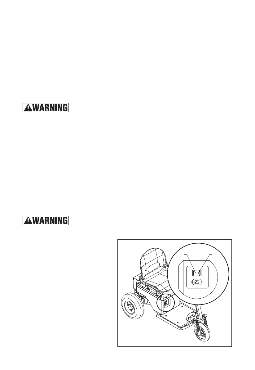
For the power supply of the console, the red knob in left hand
side is the power switch. Push on it, power is On. Push on
again, power is off. (See Fig. 14)
5.4 BATTERY LEVEL INDICATOR (See Fig. 15)
LED on battery also shows battery capacity:
1. One LED: 0~40% battery capacity.
2. Two LED: 40%~70% battery capacity.
3. Three LED: 70%~100% battery capacity.
Soft Riding Condition. When the battery is nearly depleted,
a “soft” riding condition can occur. A “soft” riding condition
means the tugger can move forward at lower speed
compared with fully charged battery. When this happens,
turn the tugger back on and drive the tugger under low
speed until you can recharge the battery.
5.5 Forward/Reverse Swtich (See Fig. 16)
Control knob in left hand side. Push upward, tugger driving
direction is forward. Push downward, driving direction is
reverse. It is normal that you engage the tugger after one
second when switch between forward/reverse. This one
second is the protection of electrical system.
Always be alert to the area around your driving path to avoid
hurting people or hitting objects!
Reversing the tugger is allowed only when nothing is being
towed. Do not reverse backwards when towing multiple trailers,
turn forward and make a U-turn!
Always bring the unit to a complete stop before shifting from
forward to reverse or from reverse to forward.
5.6 Accelerator (See Fig. 17)
Use the right thumb to control the accelerator,Slowly push the
accelerator knob to control the driving speed until reach the
desired speed. If the accelerator knob is back to the neutral
position, the controller slows the tugger until it stops.
【WRANING】Never operate at speeds that are not consistent
with operating conditions. Always limit speed to ensure adequate
time for braking in an emergency.
5.7 Turn
It is essential to slow down to a reasonably slow speed before initiating a turn. Use extreme
caution when turning on slanted or uneven surfaces. Occasionally you may find yourself
negotiating a curve or corner too fast and the inner rear wheel starts to lift off the ground. If this
happens, immediately reduce your speed, lessen the steering angle and shift your upper body
toward the wheel that is lifting off the ground.
Always be alert to the area around your driving path to avoid hurting people or hitting objects!
Fig. 14
Fig. 15
Fig. 16
Fig. 17

10
5.8 Brake & Parking (See Fig. 18)
The left brake handle is controlled mechanical brake
which lock the brake in the right rear wheel. When
actuated brake handle, It will slow the tugger down
until it comes to a complete stop. Braking performance
depends on road conditions and the load conditions
and speed of the tugger. Release the brake and the
tugger will be free again. Also, there is parking brake
at front of handle. While actuated brake handle, press
the parking brake, the right rear wheel is locked, and
tugger is in parking situation.In a safe, controlled
environment, please familiarize yourself with the braking distance of the tugger at different
speeds before operating near intersections, pedestrians and other obstacles.
Do not drive or park the tugger laden for a long time on ramps. Park the tugger on firm and
level ground.
Operators are not allowed to leave the tugger for a long time without power supply.
6. MAINTENANCE AND STORAGE
6.1 CHARGING
1. Turn the tugger power off.
2. Securely plug the charger into the charge port, and plug to power supply.
3. Connect battery to charger.
4. A solid red light on the charger indicates the battery is charging. A solid green light indicates
the battery is fully charged.
5. Remove the plug from the power supply.
6. You will not damage the battery by riding the tugger until the battery is fully discharged and
the tugger motor shuts down.
Use approved and from your dealer released original spare parts.
Charging place must be ventilated and equips with fire extinguishers.
6.2 Brakes Maintenance
1. Check the oil level in the oil cup from time to time. If it is too low or the brake does not brake,
you need to open the oil cup cover and add brake oil.
2. If there is a brake that does not brake, replace the brake pads.
3. If there is a brake that does not brake, check whether the oil circuit is damaged, and if it is
damaged, it needs to be replaced.
4. If the brake does not brake, check whether the oil pipe joint is leaking or loose, and if so,
replace the gasket or fasten the bolt.
• Hydraulic fluid escaping under pressure can have sufficient force to enter eyes and penetrate
skin. If fluid gets in eyes or skin, flush with large quantities of water and seek medical
attention.
• Wear eye protection when servicing hydraulic components or systems.
• Keep all hoses and connections in good serviceable condition. Check before start-up and
periodically during operation.
• Do not investigate for leaks with hands. Use a large piece of cardboard.
Fig. 18

6.3 Battery Replacement
Only trained technicians are allowed to maintain, charge or replace the battery.
Use approved and from your dealer released original spare parts.
Only trained technicians are allowed to do maintenance on this tugger.
Before maintaining, turn off the power and remove the trailer from the tugger.
Recycling of batteries undergoes national regulations. Please follow these regulations.
Before starting repairs which do not require battery power, always turn off the key switch, then
disconnect the battery connector from the battery to prevent accidental short circuit.
6.4 Transportation
Use proper crane equipment or forklift to place the tugger on the vehicle or other equipment for
transportation, and fix the tugger as required.
During transportation on a lorry or truck always fasten the tugger securely.
Fix the tugger with a wedge in case of accidental movement.
The lashing band used should be strong enough.
Fix the loading and unloading AIDS (pallets, wedges) with anti-slide materials.
Or fasten the tugger via the man-up platform with lashing band.
Prior to hoisting equipment, ensure that no loose bars, tools, parts, and the like are lying in or
on part of the unit, As they can cause serious injury to personnel and/or damage the unit.
6.5 Storage
Park the tugger safely and turn off the power to the tugger.
Keep machine clear of foreign objects and clean of grease/oil and other lubricants.
protect the tugger against corrosion and dust.
If you need to lift the tugger, before lifting the tugger, make sure the tugger cannot accidentally
fall, move or slide to avoid injury or damage to the machine.
Check your tugger when you use it again, including the electronic control system, battery
power, brakes, tire pressure, whether the installation is stable, etc.
7. WARRANTY
Twelve (12) months for workmanship of the product, except for wearing parts. Warranty period
starts from the product purchase date. Warranty covers material quality and workmanship only.
Warranty does not cover product for issues caused by improper usage or any operation not in
accordance with the specifications of this manual. Any modification or tampering with the
product in any way voids the warranty.
11

12
8. TROUBLE SHOOTING
Note: If you are unable to troubleshoot the tugger after trying all the solutions listed above,
contact your local dealer or our after sales department, who will be responsible for further
troubleshooting.
Problem
The scooter does
not operate.
The Scooter
Operates
Intermittently.
Short ride time
or runs slow.
Scooter is not
stopped after
actuate brake
handle, or, it
is hard to
actuate brake
handle.
Possible cause
The scooter is not turned on.
The battery is not charged.
The hand brake and parking brake
are inadvertently engaged.
The battery is not locked and secured.
Main circuit was broken.
The battery capacity is low and
cause soft riding condition.
The battery is not locked and
secured into its base.
Rider weight.
Carry dolly or heavy luggage.
Riding conditions.
Battery not fully charged.
Old/Damaged Battery.
Main circuit was not connecting
securely.
Drum brake is too loosed, or too
tighten
Solution
Turn on scooter by pressing power button.
Charge Battery.
Make sure hand brake and parking brake are
not engaged.
Secure battery by locking it in the housing.
Contact customer service at our website
(www.greatcircleus.com) or
support line: 1-866-493-0524
Recharge Battery.
Secure battery by locking it in the housing.
Do not exceed 275 lbs. (125 kg) maximum
weight limit.
Do not carry any dolly and luggage.
Use only on flat, dry surfaces. Avoid inclines
and areas with debris on surface.
Charge battery until full.
Replace Battery.
Contact customer service at our website
(www.greatcircleus.com) or
support line: 1-866-493-0524
Adjust the screw at drum brake at both sides.


Table of contents
Other Super Handy Outdoor Cart manuals