Konig & Meyer 19776 User manual

AUFSTELLANLEITUNG (A-I)
19776 Tablet-PC-Stativ
- Gleichermaßen geeignet für Bühne, Heim und Studio
- Für Tablet-PCs mit einer Breite von 160-320 mm bzw. Höhe 120-222 mmm
- Die Halterung garantiert dank eingebauter Spannzugfeder und seitlichem
-Sicherungswinkel (3) eine effektive und sichere Montage von Tablet-PCs
- Übergreifende Klemmbacken sorgen für sicheren Halt während Moosgummi-
-auflagen Vibrationsgeräusche eliminieren und das Tablet-Gehäuse schützen
- Mit Verstellmöglichkeiten die keine Wünsche offenlassen:
-Tabletgröße, Neigungswinkel, Ausrichtung, Hoch/Querformat
- Stativ stufenlos höhenverstellbar von 700 - 1550 mm
SICHERHEITSHINWEISE
- Tablet sorgfältig in die Aufnahmeplatte einklipsen und auf sicheren Sitz prüfen
- Halterung umsichtig handhaben; v.a. beim Ändern der Einstellungen (Neigung, Format, Richtung)
- der Boden muss geeignet sein, d.h. ebener und tragfähiger Untergrund ist Voraussetzung
- Verschraubungen stets handfest anziehen
- vor Wind, Regen Stößen etc. schützen
Vielen Dank, dass Sie sich für dieses Produkt entschieden haben. Diese Anleitung informiert
Sie über alle wichtigen Schritte bei Aufbau und Handhabung. Wir empfehlen, sie auch für den
späteren Gebrauch aufzubewahren.
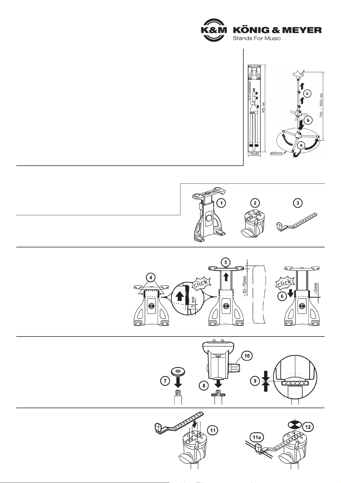
ASTATIV VORBEREITEN
Aa. Füße auseinander klappen
Ab. Sockelschraube lösen und Sockel bis zum Anschlag
Ab.nach unten fahren; Sockelschraube wieder anziehen
Ac. Spannschelle lösen, Auszüge auf gewünschte Höhe
Ac.bringen und Spannschellen wieder klemmen
BBAUGRUPPEN des 19776 ZURECHTLEGEN
B1Tablet-Halterung
B2Schwenkgelenk
B3Sicherungswinkel
CTABLET-HALTERUNG VOREINSTELLEN
C4Stellen Sie sicher, dass der "große Riegel"'
C4ausgerastet ist, was an dem 3 mm-Spalt zu
C4erkennen ist (s.Abb.)
C4Dazu den "großen Riegel" mit etwas Kraft nach
C4oben schieben. Das Ausrasten bewirkt ein
C4deutlich hörbares Geräusch (click).
C5Oberen Bügel herausziehen:
C5das Innenmaß zwischen den Haltebügeln
C5sollte ca.10-15 mm kleiner sein als die Höhe
C5bzw. Breite des Tablet-PC.
C6"Großen Riegel" wieder nach unten schieben
C6(auf hörbares Einrastgeräusch achten)
DSCHWENKGELENK mit dem Mikrofonstativ verbinden
D17Zunächst die Rändelscheibe auf den Gewindebolzen
D17des Stativs drehen - bis zum Anschlag
D18SCHWENKGELENK ebenfalls auf diesen Gewindebolzen
D18aufschrauben - nicht ganz bis zum Anschlag
D18(wir empfehlen ca. 3 Umdrehungen)
D19Rändelscheibe wieder zurückdrehen, so dass diese
D19mit dem SCHWENKGELENK spielfrei verspannt ist
D10 Flügelmutter festziehen
ESICHERUNGSWINKEL EINSETZEN
E11 Sicherungswinkel in die entsprechende
E11Aussparung des Schwenkgelenks einlegen.
E11Und zwar so, dass der seitliche Anschlag
E11am Tablet-PC anliegt (11a)
E12 Wichtig:
E12Der Tablet-PC sollte mittig auf dem Stativ
E12ausgerichtet sein (siehe Punkte 26 und 27),
E12ggf. Position des Sicherungswinkels korrigieren.
Tablet PC

19776 Tablet-PC-Stativ
AUFSTELLANLEITUNG (A-I)
Fortsetzung
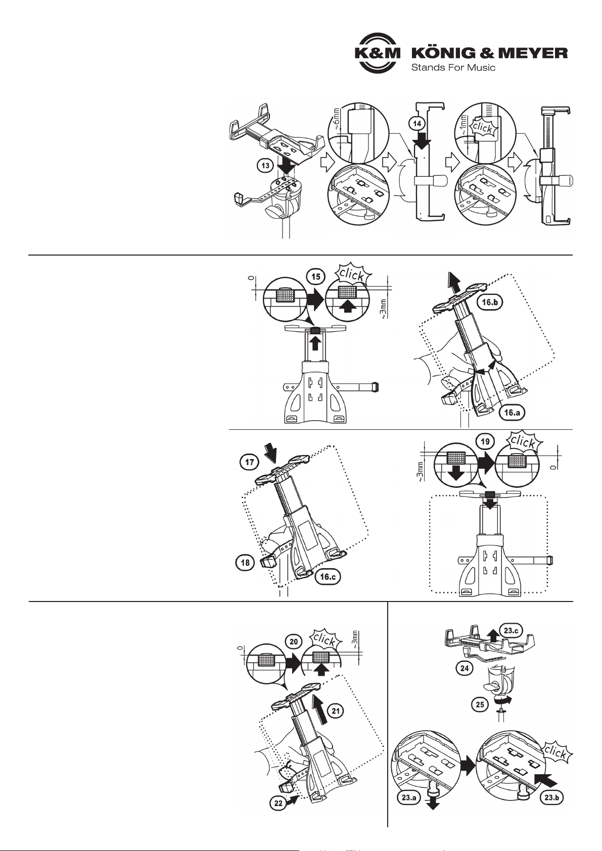
FTABLET-HALTERUNG BEFESTIGEN
F13 Tablet-Halterung auf die 4 Haken des
F13Schwenkgelenk setzen
F14 Anschließend die Halterung bis zum
F14Anschlag Richtung feste Haltebügel
F14schieben (auf hörbares Einrastgeräusch
F14achten)
GTABLET-PC IN HALTERUNG EINSETZEN
G15 "Kleinen Riegel" bis zum Anschlag
G15 nach oben schieben (Rastgeräusch!)
G15 - dadurch kann der Arm gegen eine
G15 Federkraft nach oben bewegt werden
G16.a Halterung mit einer Hand festhalten...
G16.b ...Tablet-PC mittig an den oberen
G 16.b Klemmbacken ansetzen und so weit
G 16.b hoch schieben bis der...
G16.c ...Tablet-PC auch an den untern Klemm-
G 16.c backen vollends eingelegt werden kann
G17 die Federkraft des Armes drückt den
G17Tablet-PC in die vier Moosgummiauflagen
G17der Klemmbacken
G18 BEACHTE:
G18Der Tablet-PC soll am Sicherungswinkel
G18anliegen. Je nach Größe des Tablet-PCs
G18muss die Position des Sicherungswinkel
G18korrigiert werden. Siehe I 23 ,24 & 26, 27.
G19 "Kleinen Riegel" nun nach unten
G19schieben (Rastgeräusch!) - damit sind
G19die oberen Klemmbacken wieder arretiert
HTABLET-PC AUS HALTERUNG ENTNEHMEN
H20 "Kleinen Riegel" wieder nach oben
H20schieben - dadurch ist der Auszug entsperrt
H21 Tablet-PC nehmen und damit oberen
H21Haltebügel hochdrücken
H22 Tablet-PC unten herausklappen und
H22entnehmen
IDEMONTAGE (Abb.rechts)
I(z.B. bei Anpassung des Sicherungwinkels 3)
I23 Verriegelung zwischen Tablet-Halterung
I23und Schwenkgelenk lösen:
I23.a Hebel nach unten drücken und halten
I23.b Tablet-Halterung bis zum Anschlag
I 23.b ca. 6 mm nach oben schieben
I23.c Tablet-Halterung abheben
I24 Sicherungswinkel entnehmen
I25 Bei Bedarf kann das SCHWENKGELENK
I25vom Stativ abgeschraubt werden
IDEMONTAGE
Innenansicht: Haken
zunächst eingetaucht
Innenansicht: Haken
verriegelt
19776 Tablet-PC-Stativ
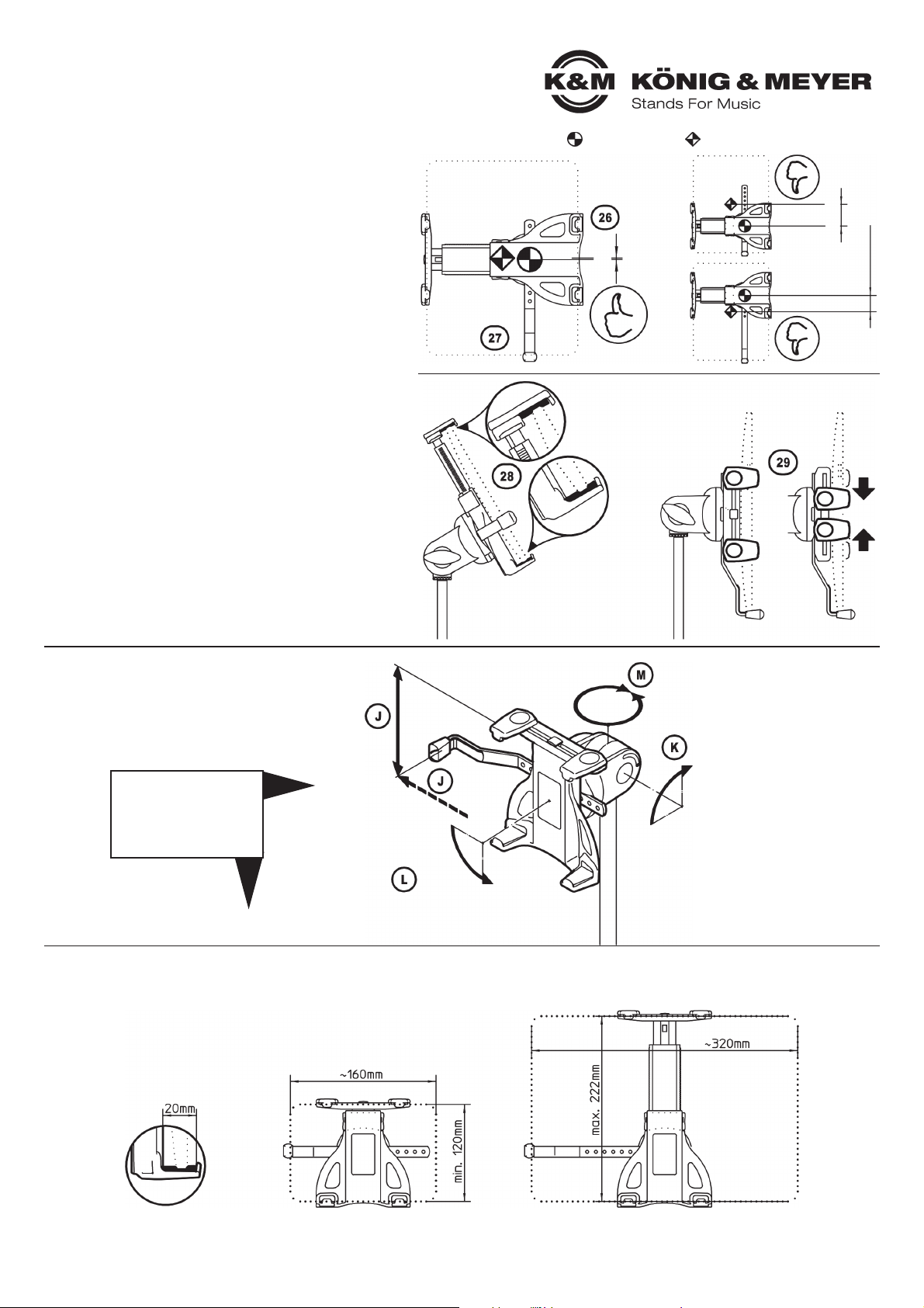
BENUTZERHINWEISE
TABLET-HALTER ANPASSEN
Dazu muss das Tablet aus der Halterung genommen werden
Maßnahmen für korrekten und sicheren Halt sind:
- Vorspannung des Haltebügels richtig einstellen (C 4-6)
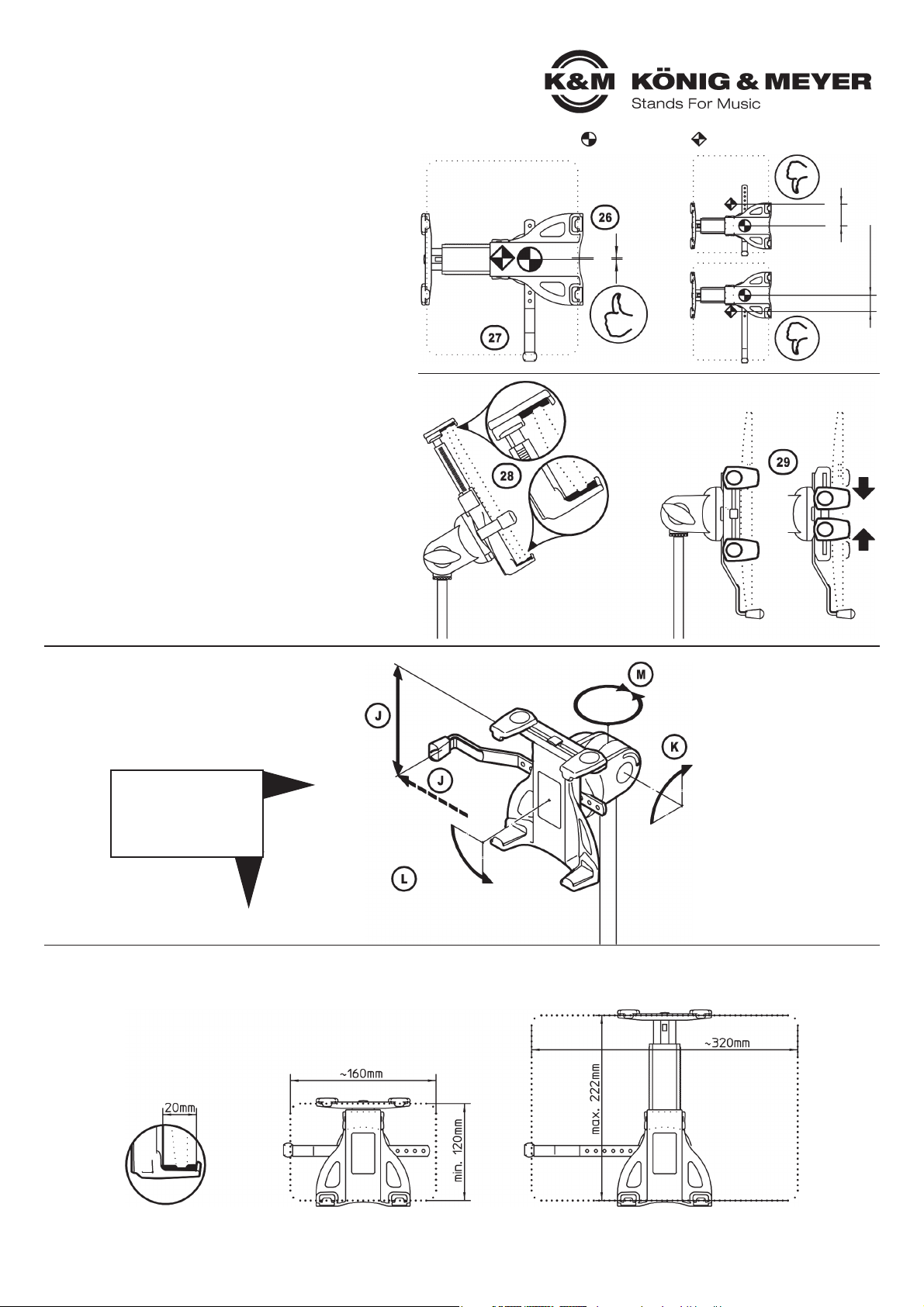
26 Tablet im Halter mittig und ausbalanciert positionieren
27 Der Sicherungswinkel sollte stets am Tablet anliegen
27 und muß sich als zusätzliche Sicherung unten befinden,
27 wenn das Tablet hochkant eingestellt ist!
28 Die weichen Moosgummiauflagen sind äußerst schonend
28 für die Oberfläche des Tablet-PC und wirken zusätzlich
28 rutschhemmend
29 Die oberen Klemmbacken können in der Breite
29 verschoben werden, z.B. um Anschlüsse zugänglich
29 zu machen.
29 Prinzipiell jedoch, sollten diese Bügel so weit wie
29 möglich auseinander stehen.
Das Einlegen des Tablets ist unter Gbeschrieben.
JTABLET-GRÖSSE
Die Bandbreite reicht von:
- min. 160 bis max. 320 mm in der Breite
- min. 120 bis max. 222 mm in der Höhe
- max. 20 mm in der Tiefe
Drehpunkt/Mittelpunkt: - des Halters, - des Tablet PCs
ABMESSUNGEN
FUNKTIONEN
EINSTELLUNGEN (J-M) Höhe:
120-222 mm
Breite:
160-320 mm
Ausrichtung:
Tablet Halter:
360°
rundum
Neigung:
senkrecht-waagrecht:
90°-schwenkbar
Format:
hoch-quer
Portrait-Landscape
90°-schwenkbar
im Überblick
&
Schritt für Schritt
mittig
außermittig
außermittig
19776 Tablet-PC-Stativ
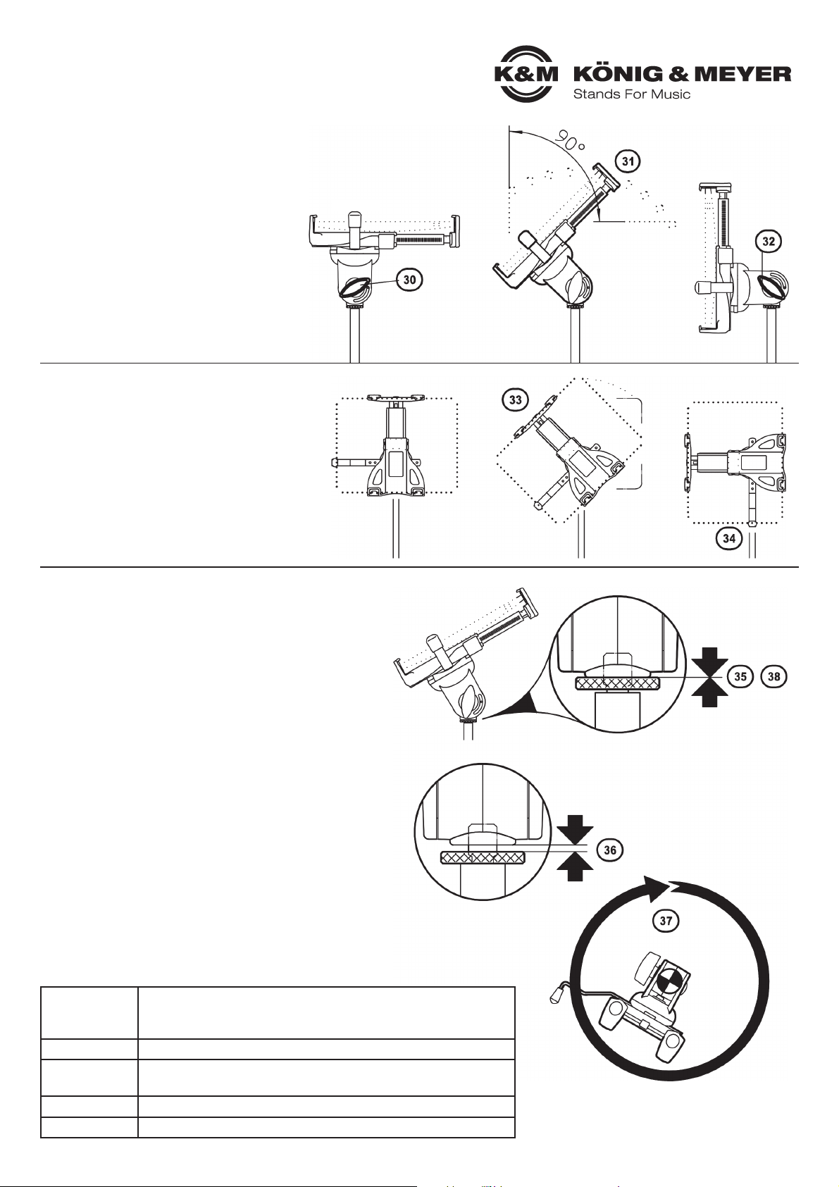
EINSTELLUNGEN
Beim Verstellen der NEIGUNG, des FORMATS
und der AUSRICHTUNG braucht das Tablet
nicht entnommen werden.
KNEIGUNG
Das Tablet kann zwischen senkrechter und
waagerechter Endstellung in jeder Position
fixiert werden.
30 Tablet halten und Flügelmutter etwas lösen
31 Tablet neigen wie gewünscht und...
32 ...Flügelmutter wieder festziehen
LFORMAT
Die Halterung verfügt über eine 90°-Verdrehfunktion.
33 Tablet halten und ins Quer- bzw. Hochformat
33 drehen - oder in die Schräge!
33 Unsichtbare Anschläge in der Halterung
33 begrenzen die Verdrehung
34 BEACHTE: Sicherungswinkel so installieren,
34 dass sich bei vertikaler Ausrichtung des Tablets
34 der Anschlag unten befindet;
34 gegebenenfalls Sicherungswinkel um 180°
34 verdreht in Schwenkgelenk einsetzten
34 (siehe Ebzw. I23, 24)
MAUSRICHTUNG
35 AUSGANGSSTELLUNG:
35 Rändelscheibe und Gewindebuchse der
35 Halterung sind miteinander verspannt
36 Durch Losdrehen der Scheibe Verspannung lösen
37 TABLET-PC-HALTERUNG in gewünschte Richtung drehen
38 Rändelscheibe und Gewindebuchse wieder
38 miteinander verspannen (siehe 35)
Material
Schwenkgelenk, Adapter, Griffe: Polyamid (PA-6)
Sicherungswinkel, Schrauben, Muttern, Scheiben, Federn: Stahl
Tablet-Halterung: PC-ABS
Traglast Tablet-PCs (Abmessungen beachten)
Abmessungen für Tablets: Breite 160-320 mm, Höhe 120-222 mmm
Stativ: ø 565 x 700/1550 mm
Karton 905 x 115 x 85 mm
Gewicht netto: 1,95 kg, brutto: 2,55 kg
FEHLERSUCHE (F) und BESEITIGUNG (B)
F: Tablet-PC wackelt
F: B: Vorspannung des oberen Haltebügels prüfen, und
F: B: ggf. korrigieren (C 4-6)
F: B: "Großen Riegel" der Halterung prüfen und falls locker
F: B: diesen einrasten (C 4-6)
F: Tablet-PC sitzt aussermittig
F: B: Seitenwinkel entsprechend positionieren (E, 26 und 27)
F: Tablet-Halterung wackelt
F: B: Verschraubungen prüfen und ggf. nachziehen (D9, K32)
F: B: Einrasten vergessen? Halterung aufsetzen und richtig
F: B: einrasten (F13und 14)
F: Tablet-Halterung lässt sich nicht vom Gelenkkörper abziehen
F: B: Erst Hebel drücken, dann Tablet-Halterung entriegeln und abziehen (I23)
TECHNISCHE DATEN / SPEZIFIKATION
KÖNIG & MEYER GmbH & Co. KG
Kiesweg 2, 97877 Wertheim, www.k-m.de
19776-300-55 Rev.13 03-80-237-00 6/17
Querformat Hochformat
Horizontal
Vertical
INSTALLATION (A-I)
19776 Tablet PC stand
- Equally suitable for the stage, home and studio
- For tablet PCs with width 160-320 mm, height 120-222 mm
-The stand holder is an effective and secure attachment system for tablet PCs:
-guaranteed by the integrated spanning tension spring and the side guard arm (3)
- A secure hold is provided by the integrated moss rubber protectors on the spanning
-clamping jaws, vibration sound is eliminated and the tablet housing protected
- Adjustment options to fulfil every requirement:
-tablet size, tilt angle, direction, portrait/landscape format
- Stand can be adjusted to any height between 700 and 1550 mm
SAFETY NOTES
- Please place the tablet PC in the cradle carefully and check for secure fit
- Manoeuvre the stand holder with care; e.g. when changing the setting (tilt, format and direction)
- The Bottom must be suited, i.e. level underground with carrying capacity is a requirement
- Always hand-tighten clamp screws
- Protection from wind, rain, impact, etc.
Thank you for choosing this product. These instructions contain information about the installation
and use of the tablet PC holder. We suggest you keep the instructions in a safe place for later use.
APREPARE THE STAND
Aa. Fold feet apart
Ab. Loosen base screw and move base down to the stop;
Ab. tight base screw again
Ac. Loosen clamps, adjust extensions to the desird height
Ac. and tighten clamps again
BLAY OUT THE COMPONENTS FOR 19776 IN ORDER
B1Tablet cradle
B2Swivel joint
B3Guard arm
CPRE-ADJUSTING THE TABLET CRADLE
C4Ensure that the "large latch" is disengaged -
C4look for the 3 mm gap (see Fig.)
C4Slide the "large latch" upwards, applying gentle
C4strength. There will be an audible click.
C5Slide out the upper section:
C5The distance between the sides should be
C5approx.10-15 mm less than the height or width
C5of the tablet PC.
C6Slide the "large latch" back down (there should
C6be an audible click)
DCONNECTING THE SWIVEL JOINT TO THE MICROPHONE STAND
D 1 7First, turn the knurled disc on the screw mounting of the stand as
D 1 7 far as it will go
D 1 8Swivel joint - also turn this on the screw mounting
D 1 8 – but not as far as it will go – we recommend leaving a
D 1 8 gap of approx. 3 turns
D 1 9Turn the knurled disc in the opposite direction until there
D 1 9 is no more free play between it and the swivel joint
D10 Tighten the wing nut
EATTACHING THE GUARD ARM
E11 Place the guard arm in a suitable groove of the
E11swivel joint in such a way that the end sits closely
E11with the tablet (11a)
E12 Important:
E12The tablet PC must be aligned centrally
E12(see points 26 and 27), if necessary, correct the
E12position of the guard arm.
Tablet PC
19776 Tablet PC stand
INSTALLATION (A-I)
Continuation
FATTACHING THE CRADLE
F13 Place the cradle on the four hooks of the
F13swivel joint
F14 Slide the cradle to the stop position (you will
F14hear a click)
GCLIP THE TABLET PC IN THE CRADLE
G15 "Move the "small latch" upwards (click!)
G15 - this allows the arm to be moved upwards
G15 against a spring tension
G16.a Hold the cradle firmly with one hand...
G16.b ...align the tablet PC centrally in the
G 16.b clamping jaw and slide upwards until...
G16.c ...the tablet PC can also be clipped into
G 16.c the lower side of clamping jaw
G17 The spring tension of the arm will push the
G17tablet PC onto the four moss rubber
G17protectors of the clamping jaw
G18 NOTE:
G18The tablet PC should sit neatly with the
G18guard arm. The position of the guard arm
G18may need to be corrected depending on the
G18size of the tablet PC. See I 23 ,24 & 26, 27.
G19 Now slide the "small latch" down (click!) -
G19the upper jaws are now securely fixed
HREMOVING THE TABLET PC FROM THE CRADLE
H20 Slide the "small latch" up again - the pull-out
H20section is now released
H21 Hold the tablet PC and use it to push out
H21the top side of the cradle
H22 Unclip the tablet PC in a downwards motion
H22and remove
IDISMANTLING (Fig.re.)
I(e.g. to re-position the guard arm 3)
I23 Release the lock between the tablet cradle
I23and the swivel joint as follows:
I23.a Press the lever down and hold down
I23.b Slide the tablet cradle upwards to stop
I 25.b approx. 6 mm
I23.c Lift the tablet cradle
I24 Remove the guard arm
I25 If required, the swivel joint can be
I25unscrewed from the stand
IDISMANTLING
Inner view: Hooks
inserted
Inner view: Hooks
locked
28 The soft moss rubber protects are effective protectors for
28 the surface of the tablet and also prevent slip
29 The upper clamping jaw can be extended widthways, e.g.
29 to access connections.
29 In general, the jaw should extended as wide as possible.
How to clip in the tablet is described in G.
19776 Tablet PC stand
USER INSTRUCTIONS
ADJUSTING THE TABLET CRADLE
First the tablet must be removed from the cradle
Ensure the cradle tension is adjusted correctly so the tablet
is held securely (C4-6)
26 Position the tablet in the holder centrally and properly
26 balanced
27 The guard arm must always touch the side of the tablet
27 and be under the tablet as additional security when the
27 tablet is positioned in the portrait format!
JTABLET SIZES
Range:
- min. 160 to max. 320 mm width
- min. 120 to max. 222 mm height
- max. 20 mm depth
fulcrum/centre point: - of the holder, - of the Tablet PC
DIMENSIONS
FUNCTIONS
SETTINGS (J-M) height:
120-222 mm
width:
160-320 mm
adjustment:
tablet holder:
360°
all around
format:
portrait-landscape
90°-swivelling
At a Glance
&
Step by Step
Angle of inclination:
vertical-horizontal:
90°-swivelling
centric
excentric
excentric

ADJUSTMENT
The tablet does not have to be removed to
adjust the TILT, FORMAT or DIRECTION of
the tablet.
KTILT
The tablet can be fixed in any position between
portrait and landscape format.
30 Hold the tablet and loosen the wing nut
30 slightly
31 Tilt the tablet as required and...
32 ...re-tighten the wind nut
LFORMAT
The cradle can be moved through 90°.
33 Hold the tablet and turn to portrait or landscape
33 format - or position at an angle!
33 Invisible stops in the cradle prevent the cradle
33 from slipping out of position
34 NOTE: the guard arm must be placed so that
34 when the cradle is in the portrait position it is at
34 the lower edge of the tablet;
34 it may be necessary to turn the guard arm 180°
34 before inserting in the swivel joint (see Ebzw.
34 I23, 24)
MDIRECTION
35 START POSITION:
35 The knurled disc and threaded bushing of the cradle
35 are tensed against each other
36 Release tension by turning the disc
37 Turn the tablet PC cradle to face the required direction
38 Tighten the knurled disc and threaded bushing again
38 (see 35)
Materials
Swivel joint, adapter, grip: polyamide (PA-6)
screws, nuts, washers, spring: steel
Tablet cradle: PC-ABS
Load Tablet-PCs (check dimensions)
Dimensions For tablets with width 160-320 mm, height 120-222 mm
For tubes: ø 11-30 mm
Box 905 x 115 x 85 mm
Weight net: 1.95 kg, gross: 2.55 kg
FAULT FINDING (F) and SOLUTION (S)
F: Tablet PC wobbles
F: S: Check the tensioning of the upper cradle jaw and if necessary
F: S: readjust (C 4-6)
F: S: Check the "large latch" of the cradle and if loose click back
F: S: in place (C 4-6)
F: Tablet PC is not positioned centrally
F: S: Re-position the guard arm (E, 26 and 27)
F: Tablet cradle wobbles
F: S: Check the screw connections and if necessary tighten (D9, K32)
F: S: Has the cradle been clipped in correctly? Repeat clipping in
F: S: procedure (F13and 14)
F: Tablet cradle cannot be released from the joint component
F: S: Press the lever, then release the tablet and remove (I23)
TECHNICAL DATA
KÖNIG & MEYER GmbH & Co. KG
Kiesweg 2, 97877 Wertheim, www.k-m.de
19776-300-55 Rev.13 03-80-237-00 6/17
19776 Tablet PC stand
Landscapeat Portrait
Horizontal
Vertical
Table of contents
Languages:
Other Konig & Meyer Tablet Accessories manuals

Konig & Meyer
Konig & Meyer 19790 User manual

Konig & Meyer
Konig & Meyer 19754 User manual

Konig & Meyer
Konig & Meyer 19728 User manual

Konig & Meyer
Konig & Meyer 19742 User manual

Konig & Meyer
Konig & Meyer 19754 User manual

Konig & Meyer
Konig & Meyer 19722 User manual

Konig & Meyer
Konig & Meyer 19800 User manual

Konig & Meyer
Konig & Meyer 19723 Manual


