KONRAD 600B SERIES INSTALLATION GUIDE JANUARY 2019 - V4.0PAGE 6
Stern Drive
General Information
The Konrad 600B Series stern drives are
designed to accommodate engines that generate
up to 1200 Nm (885 lb. ft.) of torque at maximum
rated RPM. Maximum torque ratings are drive
model and application dependent.
There is a sixteen degree (16°) trim range to
optimize vessel performance while underway.
To achieve optimal wear it is recommended that
the stern drive be operated between the +20to -20
degree trim range while under power.
There is an additional 30 degrees (30°) of lift
range that may only be used in an emergency or
when the stern drive is being serviced or transported.
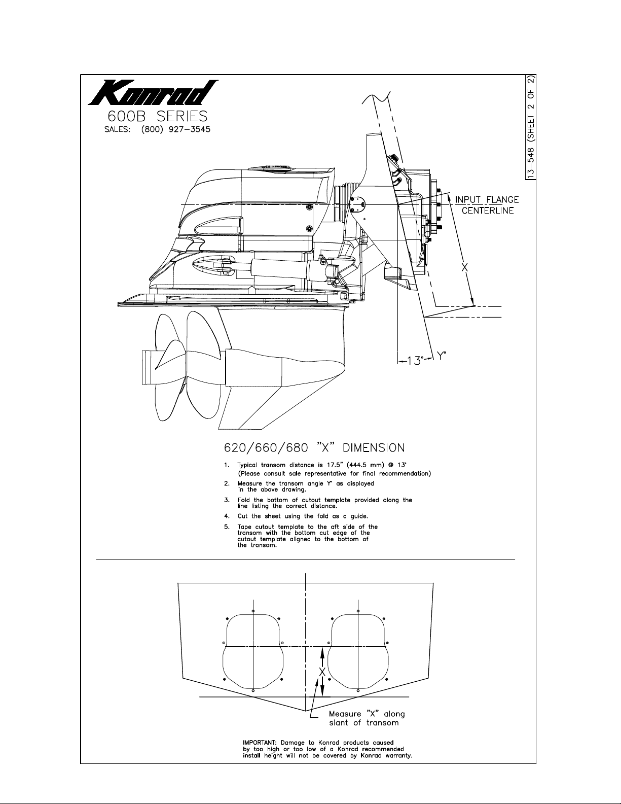
The Konrad 600B Series stern drives are
designed for applications where the vessel transom
angle is 13 degrees (13°). Applications that do not
meet this criteria may require extra equipment or
modications, or may not be possible at all. The
Konrad 620B and 680B stern drives are designed
to accommodate propellers (aluminum and
stainless steel) with a maximum diameter of 20 in.
(50.8 cm). The Konrad 660B can accommodate
propellers (aluminum and stainless steel) with a
maximum diameter of 16 in. (40.6 cm).
General Operation
The engine produces power (clockwise or
counterclockwise) that is transmitted through a re-
versing transmission. A coaxial planetary-style re-
versing transmission is normally used. The trans-
mission is connected to the stern drive via close
couple or drive shaft. The power is then transmit-
ted through a series of shafts and gears to the pro-
peller(s).
Safety Notices
Read and understand all of the safety precau-
tions and warnings before performing any installa-
tion or repair.
This list contains the general safety precautions
and warnings that MUST be followed to provide
personal safety. This list is only a suggested safe-
ty guideline. Working conditions vary greatly and
safety measures will vary upon your individual cir-
cumstances.
ALWAYS USE CAUTION. Make sure the
work area surrounding the product is safe. Be
aware of hazardous conditions that can exist.
ALWAYS wear protective eyewear and
protective footwear when working.
DO NOT wear loose-tting or torn clothing.
Remove all jewelry when working.
DO NOT work on anything that is support-
ed only by lifting jacks or a hoist.
ALWAYS use blocks or proper stands to
support the product before performing any
service work.
TO AVOID PERSONAL INJURY, use
a hoist or get assistance when lifting stern
drive components. Make sure all lifting de-
vices such as chains, hooks or slings are in
good condition and are of the correct lifting
capacity.