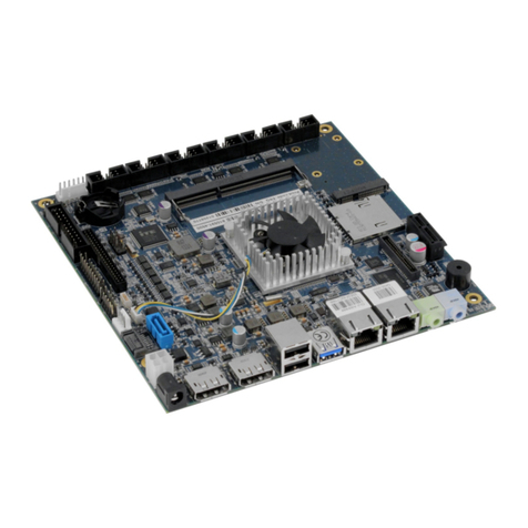
mITX-BDW-U – User Guide, Rev. 1.6
www.kontron.com // 8
Table of Contents
Symbols .................................................................................................................................................................................................................5
For Your Safety....................................................................................................................................................................................................6
High Voltage Safety Instructions ..................................................................................................................................................................6
Special Handling and Unpacking Instruction ............................................................................................................................................6
General Instructions on Usage.......................................................................................................................................................................7
Environmental Protection Statement .........................................................................................................................................................7
Life Support Policy .............................................................................................................................................................................................7
Table of Contents .............................................................................................................................................................................................. 8
1/ Introduction..........................................................................................................................................................................................10
2/ Installation Procedure .......................................................................................................................................................................11
2.1. Installing the Board ...................................................................................................................................................................................11
2.2. Chassis Safety Standards......................................................................................................................................................................12
2.3. Lithium Battery Precautions.................................................................................................................................................................13
3/ System Specifications.......................................................................................................................................................................14
3.1. Component Main Data.............................................................................................................................................................................14
3.2. mITX-BDW-U Block Diagram................................................................................................................................................................17
3.3. Processor Support Table .......................................................................................................................................................................18
3.4. System Memory Support.......................................................................................................................................................................18
3.5. mITX-BDW-U Graphics Subsystem....................................................................................................................................................19
3.6. Power Consumption................................................................................................................................................................................21
4/ Connector Locations.........................................................................................................................................................................24
4.1. mITX-BDW-U – Top View and Front Panel......................................................................................................................................24
5/ Connector Definition.........................................................................................................................................................................26
6/ I/O-Area Connectors ........................................................................................................................................................................ 27
6.1. DP Connectors DP1 and DP2 (J8, J9)................................................................................................................................................... 27
6.2. Ethernet Connectors (J4, J5) ................................................................................................................................................................28
6.3. USB Connectors (J6, J7)..........................................................................................................................................................................29
6.4. Audio Jack Connectors (J1, J2)...............................................................................................................................................................31
6.5. DC Power - Jack Connector -19 V –(J13) ............................................................................................................................................31
7/ Internal Connectors..........................................................................................................................................................................32
7.1. DC Power - ATX Connector -12 V (J10)...............................................................................................................................................32
7.2. Fan Connectors (J34, J29) .....................................................................................................................................................................32
7.3. PS/2 Keyboard and Mouse Connector (KBDMSE) (J15)............................................................................................................... 33
7.4. SATA (Serial ATA) Ports (J12, J18) .......................................................................................................................................................34
7.5. USB Connectors (Internal).................................................................................................................................................................... 35
7.6. Speaker Connector (J37)........................................................................................................................................................................ 35
7.7. Microphone Connector (J13)................................................................................................................................................................. 35
7.8. SPDIF-Out (J14)......................................................................................................................................................................................... 35
7.9. Front Panel Connector (FRONTPNL) (J23)....................................................................................................................................... 36
7.10. Serial Ports COM1 and COM2 (J21, J25) ........................................................................................................................................... 37
7.11. LVDS Flat Panel Connector (J33) .......................................................................................................................................................38
7.12. Feature Connector (J28)......................................................................................................................................................................38
7.13. “Load Default BIOS Settings” Jumper (JP1) .....................................................................................................................................41
7.14. Always On Jumper Setting (JP1) .........................................................................................................................................................41
7.15. SPI Connector (J30).................................................................................................................................................................................41
7.16. LPC Connector (J31) ...............................................................................................................................................................................42
7.17. SATA Power Connectors (J16,J20).....................................................................................................................................................42

