Kontron MicroTCA AM5901 User manual

If it’s embedded, it’s Kontron.
» User Guide «
P R E L I M I N A R Y
AM5901
MicroTCA™ Carrier Hub
Double, Full-size AMC Form Factor
Doc. ID: 1032-0648, Rev. 1.0
August 3, 2009

Preface AM5901
Page ii ID 1032-0648, Rev. 1.0
P R E L I M I N A R Y
Revision History
Imprint
Kontron Modular Computers GmbH may be contacted via the following:
MAILING ADDRESS TELEPHONE AND E-MAIL
Kontron Modular Computers GmbH +49 (0) 800-SALESKONTRON
D - 87600 Kaufbeuren Germany
For further information about other Kontron products, please visit our Internet web site:
www.kontron.com.
Disclaimer
Copyright © 2009 Kontron AG. All rights reserved. All data is for information purposes only and
not guaranteed for legal purposes. Information has been carefully checked and is believed to
be accurate; however, no responsibility is assumed for inaccuracies. Kontron and the Kontron
logo and all other trademarks or registered trademarks are the property of their respective own-
ers and are recognized. Specifications are subject to change without notice.
Publication Title: AM5901: MicroTCA™ Carrier Hub
Double, Full-size AMC Form Factor
Doc. ID: 1032-0648
Rev. Brief Description of Changes Date of Issue
1.0 Initial issue 3-Aug-2009

AM5901 Preface
ID 1032-0648, Rev. 1.0 Page iii
P R E L I M I N A R Y
Table of Contents
Revision History .........................................................................................................ii
Imprint ........................................................................................................................ii
Disclaimer ..................................................................................................................ii
Table of Contents ......................................................................................................iii
List of Tables ............................................................................................................ vii
List of Figures ...........................................................................................................ix
Proprietary Note ........................................................................................................xi
Trademarks ...............................................................................................................xi
Environmental Protection Statement .........................................................................xi
Explanation of Symbols ........................................................................................... xii
For Your Safety ....................................................................................................... xiii
High Voltage Safety Instructions ......................................................................... xiii
Special Handling and Unpacking Instructions .................................................... xiii
General Instructions on Usage ...........................................................................xiv
Two Year Warranty ...................................................................................................xv
1. Introduction ............................................................................. 1 - 3
1.1 Board Overview ....................................................................................... 1 - 3
1.2 Board-Specific Information ...................................................................... 1 - 4
1.3 System Relevant Information .................................................................. 1 - 5
1.4 Board Diagrams ...................................................................................... 1 - 5
1.4.1 Functional Block Diagram ............................................................... 1 - 5
1.4.2 Front Panel ..................................................................................... 1 - 7
1.4.3 Board Layouts ................................................................................. 1 - 8
1.5 Technical Specification ............................................................................ 1 - 9
1.6 Standards .............................................................................................. 1 - 11
1.7 Related Publications ............................................................................. 1 - 12
2. Functional Description ........................................................... 2 - 3
2.1 MCMC and Fabric [A] Switch .................................................................. 2 - 3
2.1.1 MicroTCA™ Carrier Management Controller (MCMC) ................... 2 - 3
2.1.2 Fabric [A] Switch ............................................................................. 2 - 3
2.2 Board Interfaces ...................................................................................... 2 - 4

Preface AM5901
Page iv ID 1032-0648, Rev. 1.0
P R E L I M I N A R Y
2.2.1 Front Panel LEDs ............................................................................2 - 4
2.2.2 Module Handle ................................................................................2 - 6
2.2.3 General Purpose DIP Switch ..........................................................2 - 7
2.2.4 Debug Interface ...............................................................................2 - 7
2.2.5 Management Ports ..........................................................................2 - 7
2.2.5.1 Management Serial Port .........................................................2 - 7
2.2.5.2 Management Ethernet Interface (10Base-T) ..........................2 - 8
2.2.6 Fabric [A] Ethernet Ports .................................................................2 - 8
2.2.7 Uplink Ports .....................................................................................2 - 8
2.2.7.1 Gigabit Ethernet Ports via the RJ-45 Connectors ...................2 - 9
2.2.7.2 Gigabit Ethernet Ports via the SFP Cages ...........................2 - 10
2.2.8 MCMC Reset .................................................................................2 - 11
2.3 MCH Interconnection ............................................................................. 2 - 11
2.3.1 Fabric Interface .............................................................................2 - 11
2.3.2 IPMB-L Interface ...........................................................................2 - 11
2.3.3 IPMB-0 Interface ...........................................................................2 - 11
2.3.4 MCH PWR_ON Interface ..............................................................2 - 12
2.3.5 JTAG Interface ..............................................................................2 - 12
2.3.6 Pinout of MCH Card-edge Connector J1 ......................................2 - 12
3. Installation ................................................................................ 3 - 3
3.1 Safety Requirements ...............................................................................3 - 3
3.2 Module Handle Positions .........................................................................3 - 4
3.3 Hot Swap Procedures ..............................................................................3 - 5
3.3.1 Hot Swap Insertion ..........................................................................3 - 5
3.3.2 Hot Swap Extraction ........................................................................3 - 6
4. Configuration / Power / Thermal ............................................ 4 - 3
4.1 Configuration ...........................................................................................4 - 3
4.1.1 DIP Switch SW2 Configuration .......................................................4 - 3
4.1.1.1 SW2/Switch 2 Configuration for Firmware Update .................4 - 3
4.2 Power Considerations ..............................................................................4 - 4
4.2.1 AM5901 Input Voltage Ranges .......................................................4 - 4

AM5901 Preface
ID 1032-0648, Rev. 1.0 Page v
P R E L I M I N A R Y
4.2.2 Power Requirements ...................................................................... 4 - 4
4.2.2.1 Payload Power ....................................................................... 4 - 4
4.2.2.2 Payload and Management Voltage Ramp .............................. 4 - 4
4.2.2.3 Management Power Consumption ......................................... 4 - 5
4.2.3 Payload Power Consumption of the AM5901 ................................. 4 - 5
4.2.4 IPMI FRU Payload Power Consumption ......................................... 4 - 5
4.2.5 Payload Start-Up Current of the AM5901 ....................................... 4 - 5
4.3 Thermal Considerations .......................................................................... 4 - 6
4.3.1 Thermal Monitoring ......................................................................... 4 - 6

Preface AM5901
Page vi ID 1032-0648, Rev. 1.0
P R E L I M I N A R Y
This page has been intentionally left blank.

AM5901 Preface
ID 1032-0648, Rev. 1.0 Page vii
P R E L I M I N A R Y
List of Tables
1-1 System Relevant Information ................................................................... 1 - 5
1-2 AM5901 Main Specifications .................................................................... 1 - 9
1-3 Standards ............................................................................................... 1 - 11
1-4 Related Publications .............................................................................. 1 - 12
2-1 Module LEDs Function ............................................................................. 2 - 5
2-2 User LED 0 Function ................................................................................ 2 - 5
2-3 Fabric [A] Link LEDs 12..1 Function ........................................................ 2 - 5
2-4 Module Handle Positions ......................................................................... 2 - 6
2-5 DIP Switch SW2 Functions ...................................................................... 2 - 7
2-6 Serial Port Connector J2 Pinout ............................................................... 2 - 7
2-7 Ethernet Connector J3 Pinout .................................................................. 2 - 8
2-8 Gigabit Ethernet Con. J4A..D Pinout ....................................................... 2 - 9
2-9 SFP Cages J7 and J8 Pinout ................................................................ 2 - 10
2-10 SFP/Lnk LEDs A/B Function ................................................................. 2 - 10
2-11 Pinout of MCH Card-edge Connector J1 ............................................... 2 - 13
2-12 JTAG Pins Description ........................................................................... 2 - 17
4-1 DIP Switch SW2 Functions ...................................................................... 4 - 3
4-2 SW2/Switch 2 Configuration for Firmware Update .................................. 4 - 3
4-3 DC Operational Input Voltage Ranges ..................................................... 4 - 4
4-4 AM5901 Payload Power Consumption .................................................... 4 - 5

Preface AM5901
This page has been intentionally left blank.
Page viii ID 1032-0648, Rev. 1.0
P R E L I M I N A R Y

AM5901 Preface
ID 1032-0648, Rev. 1.0 Page ix
P R E L I M I N A R Y
List of Figures
1-1 AM5901 Functional Block Diagram .......................................................... 1 - 6
1-2 AM5901 Front Panel ................................................................................ 1 - 7
1-3 AM5901 Board Layout (Top View) ........................................................... 1 - 8
1-4 AM5901 Board Layout (Bottom View) ...................................................... 1 - 8
2-1 Front Panel LEDs ................................................................................... 2 - 4
2-2 Module Handle Positions ....................................................................... 2 - 6
2-3 Serial Port Connector J2 .......................................................................... 2 - 7
2-4 Ethernet Connector J3 ............................................................................. 2 - 8
2-5 Gigabit Ethernet Connectors J4A..D ........................................................ 2 - 9
2-6 SPF Cages J7 and J8 ........................................................................... 2 - 10
3-1 Module Handle Positions ........................................................................ 3 - 4
4-1 DIP Switch SW2 ....................................................................................... 4 - 3

Preface AM5901
This page has been intentionally left blank.
Page x ID 1032-0648, Rev. 1.0
P R E L I M I N A R Y

AM5901 Preface
ID 1032-0648, Rev. 1.0 Page xi
P R E L I M I N A R Y
Proprietary Note
This document contains information proprietary to Kontron. It may not be copied or transmit-
ted by any means, disclosed to others, or stored in any retrieval system or media without the
prior written consent of Kontron or one of its authorized agents.
The information contained in this document is, to the best of our knowledge, entirely correct.
However, Kontron cannot accept liability for any inaccuracies or the consequences thereof, or
for any liability arising from the use or application of any circuit, product, or example shown in
this document.
Kontron reserves the right to change, modify, or improve this document or the product
described herein, as seen fit by Kontron without further notice.
Trademarks
This document may include names, company logos and trademarks, which are registered
trademarks and, therefore, proprietary to their respective owners.
Environmental Protection Statement
This product has been manufactured to satisfy environmental protection requirements where
possible. Many of the components used (structural parts, printed circuit boards, connectors,
batteries, etc.) are capable of being recycled.
Final disposition of this product after its service life must be accomplished in accordance with
applicable country, state, or local laws or regulations.

Preface AM5901
Page xii ID 1032-0648, Rev. 1.0
P R E L I M I N A R Y
Explanation of Symbols
Caution, Electric Shock!
This symbol and title warn of hazards due to electrical shocks (> 60V)
when touching products or parts of them. Failure to observe the pre-
cautions indicated and/or prescribed by the law may endanger your
life/health and/or result in damage to your material.
Please refer also to the section “High Voltage Safety Instructions” on
the following page.
Warning, ESD Sensitive Device!
This symbol and title inform that electronic boards and their compo-
nents are sensitive to static electricity. Therefore, care must be taken
during all handling operations and inspections of this product, in
order to ensure product integrity at all times.
Please read also the section “Special Handling and Unpacking
Instructions” on the following page.
Warning!
This symbol and title emphasize points which, if not fully understood
and taken into consideration by the reader, may endanger your health
and/or result in damage to your material.
Note ...
This symbol and title emphasize aspects the reader should read
through carefully for his or her own advantage.

AM5901 Preface
ID 1032-0648, Rev. 1.0 Page xiii
P R E L I M I N A R Y
For Your Safety
Your new Kontron product was developed and tested carefully to provide all features neces-
sary to ensure its compliance with electrical safety requirements. It was also designed for a
long fault-free life. However, the life expectancy of your product can be drastically reduced by
improper treatment during unpacking and installation. Therefore, in the interest of your own
safety and of the correct operation of your new Kontron product, you are requested to conform
with the following guidelines.
High Voltage Safety Instructions
Special Handling and Unpacking Instructions
Do not handle this product out of its protective enclosure while it is not used for operational pur-
poses unless it is otherwise protected.
Whenever possible, unpack or pack this product only at EOS/ESD safe work stations. Where
a safe work station is not guaranteed, it is important for the user to be electrically discharged
before touching the product with his/her hands or tools. This is most easily done by touching a
metal part of your system housing.
Warning!
All operations on this device must be carried out by sufficiently skilled
personnel only.
Caution, Electric Shock!
Before installing any piggybacks or carrying out maintenance opera-
tions always ensure that your mains power is switched off.
Serious electrical shock hazards can exist during all installation,
repair and maintenance operations with this product. Therefore,
always unplug the power cable and any other cables which provide
external voltages before performing work.
ESD Sensitive Device!
Electronic boards and their components are sensitive to static elec-
tricity. Therefore, care must be taken during all handling operations
and inspections of this product, in order to ensure product integrity at
all times.
Warning!
This product has gold conductive fingers which are susceptible to con-
tamination. Take care not to touch the gold conductive fingers of the
MCH Card-edge connector when handling the board.
Failure to comply with the instruction above may cause damage to the
board or result in improper system operation.

Preface AM5901
Page xiv ID 1032-0648, Rev. 1.0
P R E L I M I N A R Y
It is particularly important to observe standard anti-static precautions when changing piggy-
backs, ROM devices, jumper settings etc. If the product contains batteries for RTC or memory
backup, ensure that the board is not placed on conductive surfaces, including anti-static plas-
tics or sponges. They can cause short circuits and damage the batteries or conductive circuits
on the board.
General Instructions on Usage
In order to maintain Kontron’s product warranty, this product must not be altered or modified in
any way. Changes or modifications to the device, which are not explicitly approved by Kontron
and described in this manual or received from Kontron’s Technical Support as a special han-
dling instruction, will void your warranty.
This device should only be installed in or connected to systems that fulfill all necessary techni-
cal and specific environmental requirements. This applies also to the operational temperature
range of the specific board version, which must not be exceeded. If batteries are present, their
temperature restrictions must be taken into account.
In performing all necessary installation and application operations, please follow only the in-
structions supplied by the present manual.
Keep all the original packaging material for future storage or warranty shipments. If it is neces-
sary to store or ship the board, please re-pack it as nearly as possible in the manner in which
it was delivered.
Special care is necessary when handling or unpacking the product. Please consult the special
handling and unpacking instruction on the previous page of this manual.

AM5901 Preface
ID 1032-0648, Rev. 1.0 Page xv
P R E L I M I N A R Y
Two Year Warranty
Kontron grants the original purchaser of Kontron’s products a TWO YEAR LIMITED HARDWARE
WARRANTY as described in the following. However, no other warranties that may be granted or
implied by anyone on behalf of Kontron are valid unless the consumer has the express written
consent of Kontron.
Kontron warrants their own products, excluding software, to be free from manufacturing and
material defects for a period of 24 consecutive months from the date of purchase. This war-
ranty is not transferable nor extendible to cover any other users or long-term storage of the
product. It does not cover products which have been modified, altered or repaired by any
other party than Kontron or their authorized agents. Furthermore, any product which has
been, or is suspected of being damaged as a result of negligence, improper use, incorrect
handling, servicing or maintenance, or which has been damaged as a result of excessive cur-
rent/voltage or temperature, or which has had its serial number(s), any other markings or
parts thereof altered, defaced or removed will also be excluded from this warranty.
If the customer’s eligibility for warranty has not been voided, in the event of any claim, he may
return the product at the earliest possible convenience to the original place of purchase,
together with a copy of the original document of purchase, a full description of the application
the product is used on and a description of the defect. Pack the product in such a way as to
ensure safe transportation (see our safety instructions).
Kontron provides for repair or replacement of any part, assembly or sub-assembly at their own
discretion, or to refund the original cost of purchase, if appropriate. In the event of repair,
refunding or replacement of any part, the ownership of the removed or replaced parts reverts
to Kontron, and the remaining part of the original guarantee, or any new guarantee to cover
the repaired or replaced items, will be transferred to cover the new or repaired items. Any
extensions to the original guarantee are considered gestures of goodwill, and will be defined
in the “Repair Report” issued by Kontron with the repaired or replaced item.
Kontron will not accept liability for any further claims resulting directly or indirectly from any
warranty claim, other than the above specified repair, replacement or refunding. In particular,
all claims for damage to any system or process in which the product was employed, or any
loss incurred as a result of the product not functioning at any given time, are excluded. The
extent of Kontron liability to the customer shall not exceed the original purchase price of the
item for which the claim exists.
Kontron issues no warranty or representation, either explicit or implicit, with respect to its
products’ reliability, fitness, quality, marketability or ability to fulfil any particular application or
purpose. As a result, the products are sold “as is,” and the responsibility to ensure their suit-
ability for any given task remains that of the purchaser. In no event will Kontron be liable for
direct, indirect or consequential damages resulting from the use of our hardware or software
products, or documentation, even if Kontron were advised of the possibility of such claims
prior to the purchase of the product or during any period since the date of its purchase.
Please remember that no Kontron employee, dealer or agent is authorized to make any modi-
fication or addition to the above specified terms, either verbally or in any other form, written or
electronically transmitted, without the company’s consent.

Preface AM5901
This page has been intentionally left blank.
Page xvi ID 1032-0648, Rev. 1.0
P R E L I M I N A R Y

AM5901 Introduction
ID 1032-0648, Rev. 1.0 Page 1 - 1
Introduction
Chapter 1
1
P R E L I M I N A R Y

Introduction AM5901
Page 1 - 2 ID 1032-0648, Rev. 1.0
P R E L I M I N A R Y
This page has been intentionally left blank.

AM5901 Introduction
ID 1032-0648, Rev. 1.0 Page 1 - 3
P R E L I M I N A R Y
1. Introduction
1.1 Board Overview
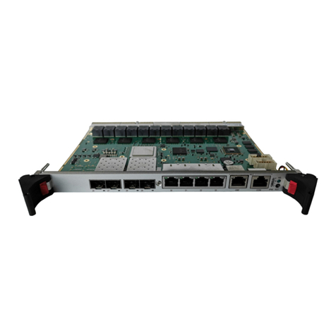
The AM5901 is a MicroTCA™ Carrier Hub (MCH) implemented in the form factor of a Double,
Full-size Advanced Mezzanine Card (AMC) Module with a single tongue. It combines the
control and management infrastructure and the interconnect fabric resources needed to sup-
port up to twelve AMC modules, up to two cooling units and up to four power modules in a
MicroTCA™ system. The MCH’s design is based on the NXP® LPC2368 microcontroller and
the Broadcom BCM5396 Gigabit Ethernet switch.
The NXP® LPC2368 microcontroller includes a 70 MHz ARM7 CPU with I²C busses for IPMB
usage and an Ethernet interface. On the AM5901, this microcontroller serves as the MicroT-
CA™ Carrier Management Controller (MCMC) with support for E-Keying, power units, cooling
units, AMC modules, sensor data records, FRU management, Ethernet interface to external
shelf manager and basic shelf management functions.
The Broadcom BCM5396 Gigabit Ethernet switch uses 16 SerDes/SGMII ports and combines
all functions of a high-speed base fabric including packet buffer, Media Access Controllers, ad-
dress management and a non-blocking switch controller.
The AM5901 itself is hot swappable and uses E-Keying to provide hot swap capability for the
FRUs installed in a MicroTCA™ system, such as AMCs, cooling units and power modules, thus
enabling them to be replaced, monitored and controlled without having to shut down the Mi-
croTCA™ system. Furthermore, it is able to monitor and control several onboard temperature
conditions of the FRUs, their board voltages and their power supply status, manage hot swap
operations, reboot them, etc.
The AM5901 supports one standard RS-232 serial port, four Gigabit Ethernet connectors and
two SFP connectors for fabric interconnection and one Ethernet port for management purposes
as well as a variety of high-speed interconnect topologies to the MicroTCA™ system, such as 12
SerDes connections in the Gigabit Ethernet Fabric [A], 12 IPMB-L interfaces, and two IPMB-0
interfaces.

Introduction AM5901
Page 1 - 4 ID 1032-0648, Rev. 1.0
P R E L I M I N A R Y
1.2 Board-Specific Information
Due to the comprehensive features of the AM5901, such as high-performance switching fabric
and flexible interconnect topologies, this MCH provides a highly scalable solution not only for
a wide range of telecom and data network applications, but also for highly integrated industrial
environment applications with solid mechanical interfacing.
Some of the AM5901's outstanding features are:
• NXP® LPC2368 microcontroller (MCMC):
• 70 MHz ARM7 CPU
• Ethernet interface
•IPMI
• Watchdog timer
• I²C busses for IPMB usage
• Broadcom BCM5396 Gigabit Ethernet switch:
• 16 SerDes/SGMII ports
• Non-blocking full-wire speed
• Low latency
• Unmanaged layer 2 switch
• Automatic address learning and aging
• 256 kB on-chip packet buffer
• Low power consumption
• MCH interconnection:
• 12 Gigabit Ethernet SerDes connections in Fabric [A]
• 12 IPMB-L interfaces
• One I²C to Carrier FRU
• Two IPMB-0 interfaces
• Full hot swap support
• Four Gigabit Ethernet ports on front I/O routed to the Fabric [A] switch (two of them are
switchable to SFP)
• One Ethernet port on front I/O for management purposes
• One serial port on front I/O (RS-232)
• JTAG interface for debugging and manufacturing purposes
• 3 Module LEDs
• 12 Fabric [A] Link LEDs
•1UserLED
• Standard temperature range: -5°C to + 55°C
• Double, Full-size AMC form factor module with a single tongue (tongue 1)
• Designed to support the following specifications:
•PICMG
®AMC.0, Advanced Mezzanine Card Specification R2.0
•PICMG
®MTCA.0 Micro Telecommunications Computing Architecture R1.0
•PICMG
®MTCA.1 Air-Cooled Rugged MicroTCA Specification R1.0, March 19, 2009
• IPMI - Intelligent Platform Management Interface Specification, v1.5
Table of contents
Other Kontron Switch manuals

Kontron
Kontron MSH8900 User manual

Kontron
Kontron ETX CD User manual

Kontron
Kontron CP933 User manual

Kontron
Kontron CP6924 User manual

Kontron
Kontron CP932 User manual

Kontron
Kontron CP6923 User manual

Kontron
Kontron VX3910 User manual

Kontron
Kontron MS1300 Series Installation and operating instructions

Kontron
Kontron CP6930-RM User manual

Kontron
Kontron MSH8900 User manual

Kontron
Kontron CP6930-1 User manual

Kontron
Kontron CP6924-RA-A User manual

Kontron
Kontron AM4904 User manual

Kontron
Kontron CP6924-1 User manual

Kontron
Kontron CP930 User manual

Kontron
Kontron CP6940 User manual

Kontron
Kontron RMVS KVM Series User manual

Kontron
Kontron CP3923 Series User manual

Kontron
Kontron RES2404-PTP-PoE User manual