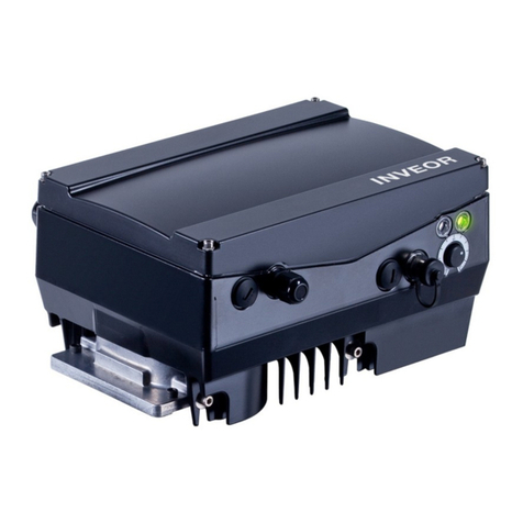
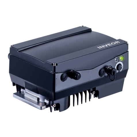
Kostal INVEOR P User manual

Operating manual
INVEOR P Drive Controller

2Operating manual for INVEOR P | DOC01695343-0001 | 2016-03 | V2.00 EN
Legal notice
KOSTAL Industrie Elektrik GmbH
An der Bellmerei 10
58513 Lüdenscheid
Germany
Tel. +49 (0)2351 16-0
Fax + 49 (0)2351 16-2400
info-industrie@kostal.com
Exclusion of liability
All names, trademarks, product names or other designations given in this
manual may be legally protected even if this is not labelled as such (e.g. as a
trademark). KOSTAL assumes no liability for their free usage.
The illustrations and texts have been compiled with great care. However, the
possibility of errors cannot be ruled out. The compilation is made without any
guarantee.
General note on gender equality
KOSTAL is aware of how language impacts on gender equality and always
makes an effort to reflect this in documentation. Nevertheless, for the sake of
readability we are unable to use non-gender-specific terms throughout and use
the masculine form instead.
© 2016 KOSTAL Industrie Elektrik GmbH
All rights reserved by KOSTAL, including those of reproduction by photocopy
and storage in electronic media. Commercial use or distribution of the texts,
displayed models, diagrams and photographs appearing in this product is not
permitted. This manual may not be reproduced, stored, transmitted or
translated in any form or by means of any medium - in whole or in part -
without prior written permission.

Contents
Operating manual for INVEOR P | DOC01695343-0001 | 2016-03 | V2.00 EN 3
1. General information ......................................................................... 6
1.1 Information about documentation........................................................ 7
1.1.1 Other applicable documents................................................................ 8
1.1.2 Storing the documentation .................................................................. 8
1.2 Notes in this manual ............................................................................ 9
1.2.1 Warnings ............................................................................................. 9
1.2.2 Warning symbols used ........................................................................ 9
1.2.3 Signal words...................................................................................... 10
1.2.4 Information notes............................................................................... 10
1.3 Symbols used in this manual ............................................................. 11
1.4 Labels on the drive controller............................................................. 12
1.5 Qualified staff..................................................................................... 13
1.6 Proper use......................................................................................... 13
1.7 Responsibility .................................................................................... 14
1.8 EU Declaration of Conformity............................................................. 15
1.9 Project planning information for housing design................................. 16
1.10 Safety instructions ............................................................................. 21
1.10.1 General information ........................................................................... 21
1.10.2 Transport & storage........................................................................... 23
1.10.3 Information about commissioning ...................................................... 23
1.10.4 Instructions concerning operation...................................................... 25
1.10.5 Maintenance and inspection .............................................................. 26
1.10.6 Repairs .............................................................................................. 27
2. Overview of the drive controller ................................................... 28
2.1 Model description size Alpha, size A - D ............................................ 29
2.2 Scope of delivery ............................................................................... 30
2.2.1 Scope of delivery for INVEOR P size Alpha ........................................ 30
2.2.2 Scope of delivery for INVEOR P size A - D......................................... 31
2.3 Description of INVEOR P drive controller ........................................... 32
3. Installation....................................................................................... 33
3.1 Safety instructions for installation....................................................... 34
3.2 Recommended preliminary fuses / line protection.............................. 35
3.3 Installation requirements for INVEOR P size Alpha ............................. 36
3.3.1 Suitable ambient conditions (see chapter 1.9).................................... 36

Contents
4Operating manual for INVEOR P | DOC01695343-0001 | 2016-03 | V2.00 EN
3.3.2 Basic connection versions/power connections
(INVEOR P size Alpha) ....................................................................... 37
3.3.3 Basic connection versions/power connections
(INVEOR P size A 1 IV02 [1 x 230 V AC]) ........................................... 39
3.3.4 Basic connection versions/power connections
(INVEOR P size A IV01 [3 x 400 V AC]) .............................................. 41
3.3.5 Basic connection versions (INVEOR P size B IV01 [3 x 400 V AC]) .... 43
3.3.6 Basic connection versions (INVEOR P size C IV01 [3 x 400 V AC]) .... 45
3.3.7 Basic connection versions (INVEOR P size D IV01 [3 x 400 V AC]) .... 47
3.3.8 Short circuit and ground protection ................................................... 49
3.3.9 Requirements of the brake resistors to use........................................ 49
3.4 Wiring instructions ............................................................................. 50
3.4.1 Wiring instructions for control terminals INVEOR P size Alpha ........... 50
3.4.2 Wiring instructions for control terminals INVEOR P size A-D .............. 51
3.4.3 Preventing electromagnetic interferences .......................................... 52
3.5 Installing the INVEOR P ..................................................................... 53
3.5.1 Mechanical installation....................................................................... 53
3.5.2 Wiring diagram for INVEOR P size Alpha ........................................... 54
3.5.3 Electrical installation for INVEOR P size Alpha.................................... 55
3.5.4 Electrical installation for INVEOR P size A-B....................................... 59
3.5.5 Electrical installation for INVEOR P size C-D ...................................... 62
3.5.6 Connection diagram for INVEOR P size A-D ...................................... 65
4. Commissioning ............................................................................... 71
4.1 Commissioning of INVEOR P size Alpha............................................ 71
4.2 Commissioning INVEOR P size A-D................................................... 71
5. Parameter........................................................................................ 72
5.1 Parameters for INVEOR P size Alpha................................................. 72
5.2 Parameters for INVEOR P size A-D.................................................... 72
6. Error detection and troubleshooting............................................ 73
6.1 Error detection and troubleshooting for INVEOR P size Alpha............ 73
6.2 Error detection and troubleshooting for INVEOR P size A-D .............. 73

Contents
Operating manual for INVEOR P | DOC01695343-0001 | 2016-03 | V2.00 EN 5
7. Disassembly and disposal ............................................................. 74
7.1 Drive controller disassembly .............................................................. 74
7.2 Information on correct disposal ......................................................... 74
8. Technical data ................................................................................ 75
8.1 General data...................................................................................... 76
8.1.1 General technical data for 230 V/400 V devices ................................ 76
9. Optional accessories...................................................................... 79
9.1 MMI handheld controller including a 3 m
RJ9 connection cable with M12 plug................................................. 81
9.2 MMI*/connecting cable PIN assignment ............................................ 82
9.3 PC communication cable USB on M12/RS485 plug
(converter integrated)......................................................................... 83
9.4 Adapter cable for INVEOR P size Alpha ............................................. 84
9.5 Internal potentiometer........................................................................ 84
9.6 MMI M12 plug (JST plug)................................................................... 85
9.7 CANopen connection cable............................................................... 86
9.8 PROFIBUS connection cable............................................................. 87
9.9 Ethercat/PROFINET/Sercos III connection cable................................ 88
9.10 Thermal conductivity paste................................................................ 89
10. Approvals, standards and guidelines........................................... 90
10.1 EMC limit classes .............................................................................. 91
10.2 Classification acc. to IEC/EN 61800-3............................................... 92
10.3 Standards and guidelines .................................................................. 92
10.4 UL approval....................................................................................... 93
10.4.1 UL Specification (English version)....................................................... 93
10.4.2 Homologation CL (Version en française) ............................................ 96
Mentions obligatoires .............................................................................. 98
11. Index .............................................................................................. 101

6Operating manual for INVEOR P | DOC01695343-0001 | 2016-03 | V2.00 EN
1. General information
1.1 Information about documentation........................................................ 7
1.1.1 Other applicable documents................................................................ 8
1.1.2 Storing the documentation .................................................................. 8
1.2 Notes in this manual ............................................................................ 9
1.2.1Warnings ............................................................................................. 9
1.2.2 Warning symbols used ........................................................................ 9
1.2.3 Signal words...................................................................................... 10
1.2.4 Information notes............................................................................... 10
1.3 Symbols used in this manual ............................................................. 11
1.4 Labels on the drive controller............................................................. 12
1.5 Qualified staff..................................................................................... 13
1.6 Proper use......................................................................................... 13
1.7 Responsibility .................................................................................... 14
1.8 EU Declaration of Conformity............................................................. 15
1.9 Project planning information for housing design................................. 16
1.10 Safety instructions ............................................................................. 21
1.10.1 General information ........................................................................... 21
1.10.2 Transport & storage........................................................................... 23
1.10.3 Information about commissioning ...................................................... 23
1.10.4 Instructions concerning operation...................................................... 25
1.10.5 Maintenance and inspection .............................................................. 26
1.10.6 Repairs .............................................................................................. 27

General information
Operating manual for INVEOR P | DOC01695343-0001 | 2016-03 | V2.00 EN 7
Thank you for choosing an INVEOR P drive controller (Cold Plate) from
KOSTAL Industrie Elektrik GmbH! Our INVEOR line of drive controllers is
designed to be universally usable with all common motor types.
If you have any technical questions, please call our central service hotline:
Tel.: +49 (0)2331 80 40-848
Monday to Friday: 7 am to 5 pm (UTC/GMT +1)
Fax: +49 (0)2331 80 40-602
E-mail: INVEOR-service@kostal.com
Website
www.kostal-industrie-elektrik.com
1.1 Information about documentation
The following information explains how to navigate through the documentation.
Read this manual carefully in its entirety. It contains important information for
operating the INVEOR P.
We assume no liability for any damage resulting from non-observance of this
manual.
This manual is an integral part of the product and applies exclusively to the
INVEOR P from KOSTAL Industrie Elektrik GmbH.
Provide the operator of the system with this manual so it is available when
needed.

General information
8Operating manual for INVEOR P | DOC01695343-0001 | 2016-03 | V2.00 EN
1.1.1 Other applicable documents
This refers to all manuals that describe how to operate the drive controller
system and any other manuals for the equipment used. Download the 3D files
(.stp) for INVEOR P from
www.kostal-industrie-elektrik.com.
A description of parameters is available for download (www.kostal-industrie-
elektrik.com) for parametrising the drive controller system. In the download,
you will find all the information required for correct parameterisation.
1.1.2 Storing the documentation
Store this operating manual and all other applicable documents carefully so
they are available when needed.

General information
Operating manual for INVEOR P | DOC01695343-0001 | 2016-03 | V2.00 EN 9
1.2 Notes in this manual
1.2.1 Warnings
DANGER
Risk of death due to electrical shock!
Death or serious injury!
De-energise drive controller and secure it against being restarted.
Fig.: 1Structure of the warnings
1 Warning symbol
2 Signal word
3 Type of danger and its source
4 Possible consequence(s) of failure to comply
5 Corrective actions
1.2.2 Warning symbols used
Danger
Danger due to electrical shock and discharge
Danger due to burns
Danger due to electromagnetic fields
1
2
5
3
4

General information
10 Operating manual for INVEOR P | DOC01695343-0001 | 2016-03 | V2.00 EN
1.2.3 Signal words
Signal words are used to identify the severity of the danger.
DANGER
Indicates a direct hazard with a high level of risk, which, if not avoided, will
result in death or serious injury.
WARNING
Indicates a hazard with a moderate level of risk, which, if not avoided, will result
in death or serious injury.
CAUTION
Indicates a hazard with a low level of risk, which, if not avoided, may result in
minor or slight injury or property damage.
1.2.4 Information notes
Information notes contain important instructions for the installation and
problem-free operation of the drive controller. These must be followed at all
times. The information notes also point out that failure to observe may result in
damage to property or financial damages.
IMPORTANT
INFORMATION
The drive controller may only be assembled, operated, maintained
and installed by trained and qualified staff.
Fig.: 2Example of an information note

General information
Operating manual for INVEOR P | DOC01695343-0001 | 2016-03 | V2.00 EN 11
Symbols within the information notes
Important information
Damage to property possible
Other notes
INFORMATION
Enlarged view
1.3 Symbols used in this manual
Symbol Meaning
1., 1., 3. … Consecutive steps in a handling instruction
Effect of a handling instruction
Final result of a handling instruction
List
Fig.: 3 Symbols and icons used
Abbreviations used
Abbreviation Explanation
Tab. Table
Fig. Figure
It. Item
Ch. Chapter

General information
12 Operating manual for INVEOR P | DOC01695343-0001 | 2016-03 | V2.00 EN
1.4 Labels on the drive controller
Fig.: 4 Type plate on the drive controller
Signs and labels are affixed to the drive controller. These may not be altered or
removed.
Symbol Meaning
Danger due to electrical shock and discharge
Danger due to electrical shock and discharge.
Wait two minutes (discharge time of the capacitors) after shut-
down
Additional earth connection
Observe and read operating manual

General information
Operating manual for INVEOR P | DOC01695343-0001 | 2016-03 | V2.00 EN 13
1.5 Qualified staff
In the context of this operating manual, qualified staff refers to electronics
specialists who are familiar with the installation, assembly, commissioning and
operation of the drive controller and the dangers involved, and whose specialist
training and knowledge of relevant standards and regulations provide them
with the necessary abilities.
1.6 Proper use
If the device is installed in a machine, drive controllers may not be
commissioned (i.e. intended operation may not begin) until it has been
determined that the machine complies with the regulations of EC Directive
2006/42/EC (Machinery Directive); DIN EN 60204-1; VDE 0113-1:2007-06
must be observed.
Commissioning (i.e. beginning intended operation) is only permitted if the EMC
Directive (2004/108/EC) is complied with.
The harmonised standards of DIN EN 50178; VDE 0160:1998-04 must be
applied for this drive controller along with DIN EN 60439-1; VDE 0660-
500:2005-01.
This drive controller may not be operated in areas where there is a danger of
explosion!
Repairs may only be performed by authorised repair bodies. Independent and
unauthorised intervention may result in death, injury or property damage. The
warranty provided by KOSTAL will be invalidated in such cases.
IMPORTANT
INFORMATION
Using drive controllers in equipment that is not fixed is considered
as an exceptional environmental condition and is only permitted if
allowed by the standards and guidelines applicable on site.

General information
14 Operating manual for INVEOR P | DOC01695343-0001 | 2016-03 | V2.00 EN
1.7 Responsibility
As a basic principle, electronic devices are not fail-safe. The operator and/or
the contractor setting up the machine or system is responsible for ensuring
that the drive switches to a safe state if the device fails.
The “Electrical equipment of machines” section in DIN EN 60204-1; VDE 0113-
1:2007-06, “Safety of machinery” describes the safety requirements for
electrical control units. These are provided for the safety of people and
machines and must be observed in order to retain the functional capability of
the machine or system.
An emergency stop feature does not have to result in the voltage supply to the
drive being switched off. To avoid dangerous situations, it may be useful for
individual drives to remain operational or for specific safety procedures to be
initiated. The effectiveness of emergency stop measures is evaluated by means
of a risk assessment for the machine or system and its electrical equipment,
and is determined by selecting a circuit category according to DIN EN 13849
“Safety of machinery – Safety-related parts of control systems”.

General information
Operating manual for INVEOR P | DOC01695343-0001 | 2016-03 | V2.00 EN 15
1.8 EU Declaration of Conformity
KOSTAL Industrie Elektrik GmbH hereby declares that the drive controller
described in this document complies with the basic requirements and other
relevant conditions of the directives listed below.
Directive 2014/30/EU
on the approximation of the laws of the Member States relating to
electromagnetic compatibility (EMC)
Directive 2014/35/EU
on the harmonisation of the laws of the Member States relating to the
making available on the market of electrical equipment designed for use
within certain voltage limits – for short: Low Voltage Directive)
The declaration of conformity for the M product family of the INVEOR serves as
an example. This can be found at:
www.kostal-industrie-elektrik.com
INFORMATION
INVEOR P is a component solely intended for installation in the final
application during the distributor's installation.
Electrical safety is heavily dependent on the precautionary
measures taken by the distributor during installation in the final
application .
IMPORTANT
INFORMATION
CE marking is the sole responsibility of the distributor.
Note the project planning information (chapter 1.9) for details.

General information
16 Operating manual for INVEOR P | DOC01695343-0001 | 2016-03 | V2.00 EN
1.9 Project planning information for housing design
The following information should help you produce the housing
design.
IMPORTANT
INFORMATION
Compliance with all project planning information is the sole
responsibility of the system integrator!
IMPORTANT
INFORMATION
Contact surface to the cooler
The drive controller can either be cooled by a sufficiently large
installation plate or an additional cooler.
Evenness required of contact surface = 0.05 mm
Maximum roughness of contact surface = RZ 6
IMPORTANT
INFORMATION
Applying the thermal conductivity paste
Coat the surfaces between the installation plate (Cold Plate) and
cooler with thermal conductivity paste (layer thickness 30 – 70 µ).
Article no. of thermal conductivity paste 10139778
IMPORTANT
INFORMATION
"IGBT temperature" shutdown threshold
IGBT module at transition to cooling element.
If the cooling element is not adequately dimensioned or if heat
transfer between the INVEOR installation plate and cooling element
provided by the customer is not properly implemented (thermal
conductivity paste not used or poorly applied, foreign bodies on
cooling surface), the drive controller shuts down at 95 °C
(measured in the power module) with the error message "IGBT
temperature".

General information
Operating manual for INVEOR P | DOC01695343-0001 | 2016-03 | V2.00 EN 17
IMPORTANT
INFORMATION
"Interior temperature" shutdown threshold
Temperature in device interior
If the temperature in the device interior is too high because the
removal of lost heat via the housing has been inadequately
dimensioned, the drive controller shuts down at an interior
temperature of 85 °C. The "Interior temperature" error message is
displayed.
IMPORTANT
INFORMATION
Testing the heat transfer
The heat transfer and installation on the customer's cooling element
must be verified during the prototype phase by a customer test.
Active cooling plate dimensions
Size
Output
Active cooling surfaces
[kW]
B [mm]
H [mm]
Alpha
0.75
120
210
A
1.5
150
261.5
B
4.0
185
300
C
7.5
220
330
D
22
270
343

General information
18 Operating manual for INVEOR P | DOC01695343-0001 | 2016-03 | V2.00 EN
Max. thermal resistance of customer's cooler
•Rated output of size
Size Performance
categories
Rth
[K/W]
For ambient temp.
Alpha, 1 x 230 VAC PW04
0.75 kW 0.688 50 °C
A, 1 x 230 VAC
PW05 1.10 kW
0.186
50 °C
A, 3 x 400 VAC PW06
1.50 kW 0.431 50 °C
B, 3 x 400 VAC
PW07 4.00 kW
0.280
50 °C
C, 3 x 400 VAC
PW11 7.50 kW
0.117
50 °C
D, 3 x 400 VAC
PW13 15.00 kW
0.087
40 °C
D, 3 x 400 VAC
PW15 22.00 kW
0.037
40 °C
IMPORTANT INFORMATION
Size D
Active cooling of size D is recommended to reduce the size of the
cooling element.
DANGER
Risk of death due to electrical shock!
Death or serious injury!
Spacing and insulation
The power-conducting plate and parts of the application PCB have a
potential of up to 400 V to PE (housing).
Spacing of 10 mm should therefore be planned between the metallic
housing and printed circuit boards and between components on the printed
circuit boards and the 20-pin ribbon cable.
Use an insulating film with a voltage resistance of at least 600 V at points
where this spacing isn't provided.

General information
Operating manual for INVEOR P | DOC01695343-0001 | 2016-03 | V2.00 EN 19
WARNING
Risk of death due to electrical shock!
Death or serious injury!
Degree of contamination
The INVEOR P drive controller may only be installed in housings complying
with at least degree of contamination 2.
This is usually ensured by the IP55 housing (or larger).
Customers must create equivalent or better conditions (degree of
contamination 1) in their housings.
Key for degree of contamination 1
Only dry, non-conductive contamination is present if any, e.g. in clean, dry
rooms or rooms with air conditioning.
Key for degree of contamination 2
Only non-conductive contamination is present. Temporary conductivity
caused by condensation must be expected occasionally, e.g. in
laboratories, precision mechanics workshops, test fields, sales showrooms.
DANGER
Risk of death due to electrical shock!
Death or serious injury!
Live parts
Attach a warning notice in accordance with IEC 60417-5036 (2002-
10) to the last housing part removed (with tool) before accessing live
parts.

General information
20 Operating manual for INVEOR P | DOC01695343-0001 | 2016-03 | V2.00 EN
DANGER
Risk of death due to
electrical shock
!
Death or serious injury!
De-energise drive controller and secure it against being restarted.
Danger due to electrical shock and discharge. Wait two minutes
(discharge time of the capacitors) after shut-down
Fitting the warning notice is the sole responsibility of the system
integrator!
WARNING
Fire hazard due to short-circuit current!
Serious burns!
In sizes C and D, the brake chopper – IGBT is smaller than the rest of the
output stage.
Because the preliminary fuses are designed for the nominal values of the
output stage, it is very possible that the fuse will not trip directly and the
brake chopper's short-circuit current will exist for a long time.
Fires may result.
The INVEOR standard housing is not critical in this regard.
Table of contents
Other Kostal Controllers manuals
Popular Controllers manuals by other brands

Johnson Controls
Johnson Controls Joventa DMS1.1 installation instructions

Newport
Newport i/8 quick start

Victron energy
Victron energy BlueSolar MPPT 75/10 manual

lapara
lapara AVR-2000 user manual

Spa-Quip
Spa-Quip SP601 Installation & service manual

Webasto
Webasto SmarTemp Control fx Installation and operation instructions