Kowa nonmyd 7 User manual

GG-09004 Edition 4.0
Edition 4.0
2014.8
Model Name K9L39F5K/E(D90 model)
K9L39F5BE(D90 model)
K9L39F7K/E(D5100 model)
K9L39F7BE(D5100 model)
K9L39F(H)8K/E(D7000 model)
K9L39F(H)8BE(D7000 model)
K9L39F(H)9K/E(D5200 model)
K9L39F(H)9BE(D5200 model)

GG-09004 Edition 4.0
- 1 -
Contents
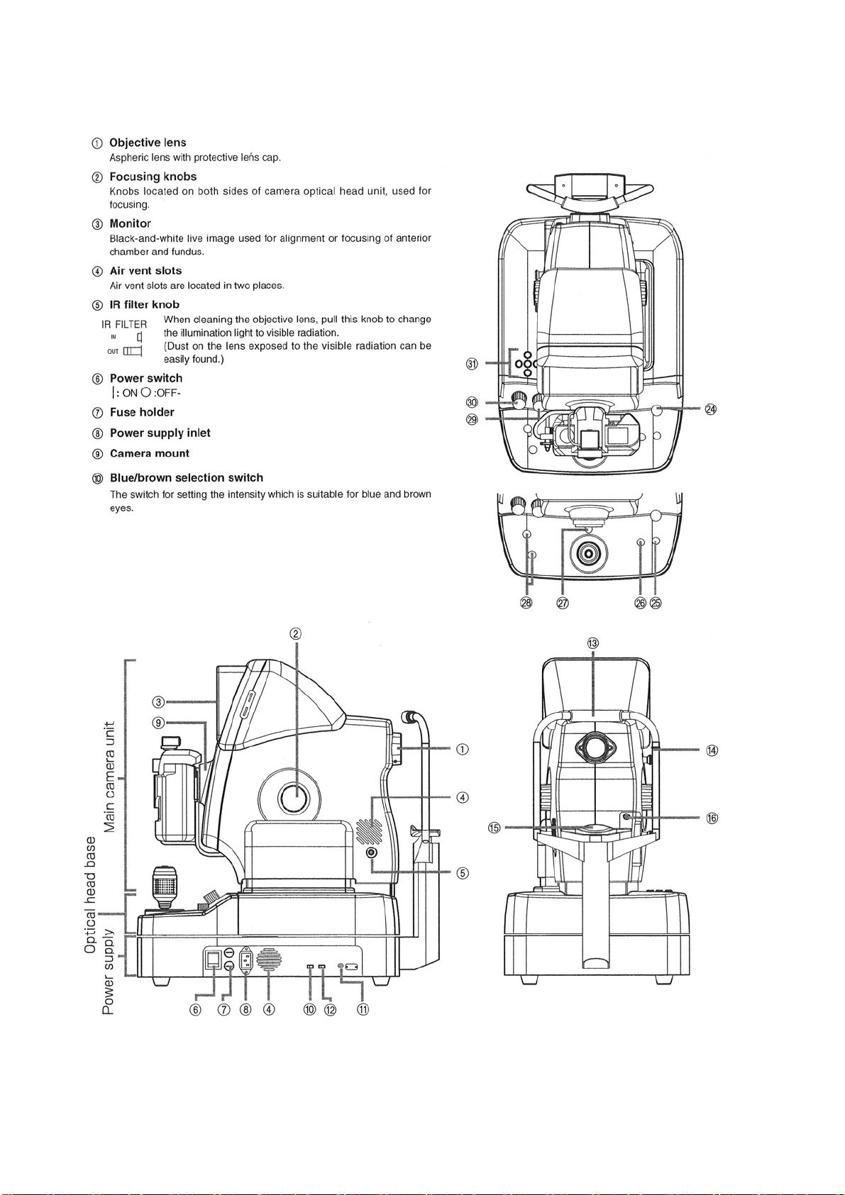
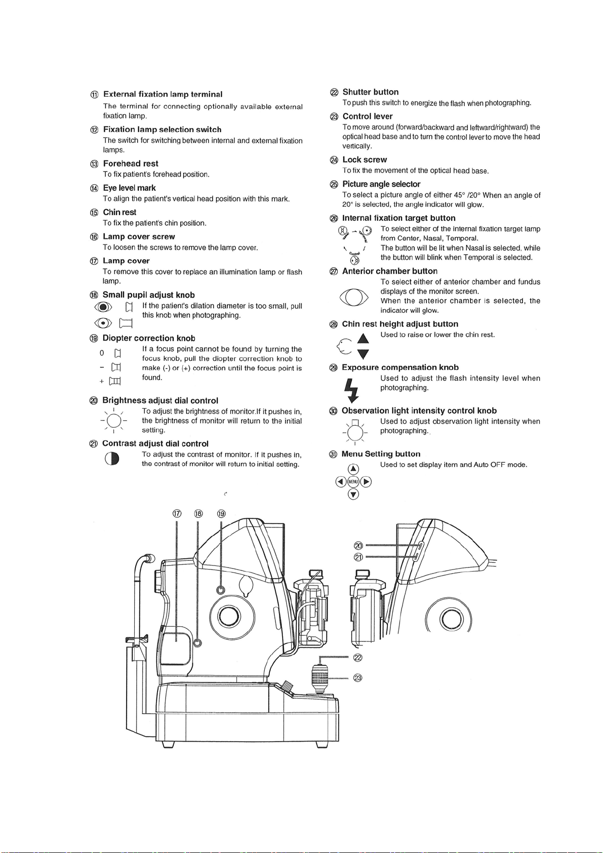
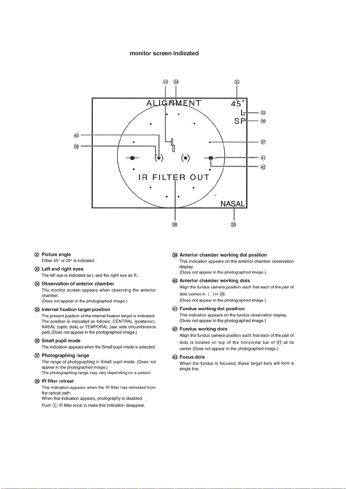
1. Names and Functions of Components ・・・・・・・・・・・・・・・・・・・・・・・・・・・・・・・・・ 3
2. Description of the principle of nonmyd 7 photography ・・・・・・・・・・・・・・・・・・・・ 6
2-1 Summary of equipment ・・・・・・・・・・・・・・・・・・・・・・・・・・・・・・・・・・・・・・・・・ 6
2-2 Photography procedure ・・・・・・・・・・・・・・・・・・・・・・・・・・・・・・・・・・・・・・・・ 6
2-3 Optical principle of photography ・・・・・・・・・・・・・・・・・・・・・・・・・・・・・・・・・ 6
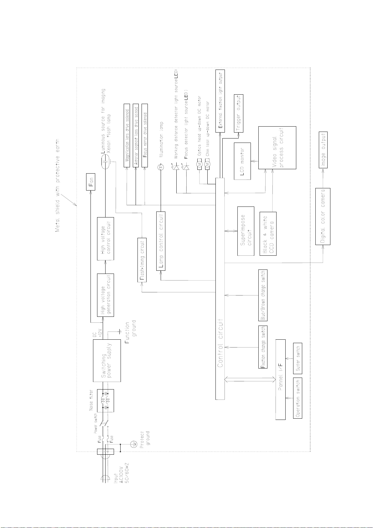
2-4 BLOCK DIAGRAM ・・・・・・・・・・・・・・・・・・・・・・・・・・・・・・・・・・・・・・・・・・・・ 8
3. Wiring Diagram ・・・・・・・・・・・・・・・・・・・・・・・・・・・・・・・・・・・・・・・・・・・・・・・・・・・・ 9
3-1 K9L39F5 ・・・・・・・・・・・・・・・・・・・・・・・・・・・・・・・・・・・・・・・・・・・・・・・・・・・・ 9
3-2 K9L39F5B ・・・・・・・・・・・・・・・・・・・・・・・・・・・・・・・・・・・・・・・・・・・・・・・・・・・ 10
3-3 K9L39F7/F8/H8 ・・・・・・・・・・・・・・・・・・・・・・・・・・・・・・・・・・・・・・・・・・・・ 11
3-4 K9L39F7B/F8B/H8B ・・・・・・・・・・・・・・・・・・・・・・・・・・・・・・・・・・・・・・・・・・・ 12
4. Preparing for Part Replacement ・・・・・・・・・・・・・・・・・・・・・・・・・・・・・・・・・・・・・・ 13
4-1 Removing outer cover ・・・・・・・・・・・・・・・・・・・・・・・・・・・・・・・・・・・・・・・・・・ 13
4-2 Removing the power supply ・・・・・・・・・・・・・・・・・・・・・・・・・・・・・・・・・・・・・・ 14
4-3 Removing the optical head base ・・・・・・・・・・・・・・・・・・・・・・・・・・・・・・・・・・ 14
5. Replacing parts ・・・・・・・・・・・・・・・・・・・・・・・・・・・・・・・・・・・・・・・・・・・・・・・・・・・ 15
5-1 Replacing parts list ・・・・・・・・・・・・・・・・・・・・・・・・・・・・・・・・・・・・・・・・・・・ 15
5-2 Replacing parts ・・・・・・・・・・・・・・・・・・・・・・・・・・・・・・・・・・・・・・・・・・・・・・ 18
The main body relation
①-1 Replacing the head board ・・・・・・・・・・・・・・・・・・・・・・・・・・・・・・ 18
①-2 Replacing the trigger board ・・・・・・・・・・・・・・・・・・・・・・・・・・・・・ 18
①-3 Replacing the discharge board ・・・・・・・・・・・・・・・・・・・・・・・・・・ 18
①-4 Replacing the internal fixation light LED board ・・・・・・・・・・・・・ 19
①-5 Disconnect the W.D. LED connector ・・・・・・・・・・・・・・・・・・・・・ 19
①-6 Replacing the anterior chamber LED ・・・・・・・・・・・・・・・・・・・・・ 19
①-7 Replacing the diopter correction sensor ・・・・・・・・・・・・・・・・・・ 20
①-8 Replacing the IR filter switch ・・・・・・・・・・・・・・・・・・・・・・・・・・・ 20
①-9 Replacing the SP knob switch ・・・・・・・・・・・・・・・・・・・・・・・・・・ 20
①-10 Replacing the magnification lens solenoid ・・・・・・・・・・・・・・・・ 21
①-11 Replacing the anterior chamber lens solenoid ・・・・・・・・・・・・・ 21
①-12 Replacing the FD return mirror solenoid ・・・・・・・・・・・・・・・・・・ 21
①-13 Replacing the fan on the optical head ・・・・・・・・・・・・・・・・・・・・ 22
①-14 Replacing the objective lens ・・・・・・・・・・・・・・・・・・・・・・・・・・・ 22
The optical head base relation
②-1 Replacing the switch panel board ・・・・・・・・・・・・・・・・・・・・・・・・ 22
②-2 Replacing CPU board ・・・・・・・・・・・・・・・・・・・・・・・・・・・・・・・・・・ 22
②-3 Replacing the menu switch board ・・・・・・・・・・・・・・・・・・・・・・・・ 23
②-4 Replacing the battery ・・・・・・・・・・・・・・・・・・・・・・・・・・・・・・・・・・ 23
②-5
Replacing the lamp volume knob and the flash light intensity selection switch
・・・・ 23
②-6 Replacing joystick ・・・・・・・・・・・・・・・・・・・・・・・・・・・・・・・・・・・・・ 24
②-7 Cleaning the friction plate unit ・・・・・・・・・・・・・・・・・・・・・・・・・・・ 24
②-8 Replacing the friction plate ・・・・・・・・・・・・・・・・・・・・・・・・・・・・・ 24
②-9 Replacing photo sensor unit ・・・・・・・・・・・・・・・・・・・・・・・・・・・・ 25
②-10 Replacing right /left selection switch ・・・・・・・・・・・・・・・・・・・・ 25
②-11 Replacing the chin rest motor ・・・・・・・・・・・・・・・・・・・・・・・・・・ 25
②-12 Replacing the optical head drive motor ・・・・・・・・・・・・・・・・・・・ 26

GG-09004 Edition 4.0
- 2 -
Power supply relation
③-1 Replacing the power board ・・・・・・・・・・・・・・・・・・・・・・・・・・・・・ 26
③-2 Replacing the video board ・・・・・・・・・・・・・・・・・・・・・・・・・・・・・・ 26
③-3 Replacing the fan on the power supply ・・・・・・・・・・・・・・・・・・・・ 27
③-4 Replacing the camera connection board ・・・・・・・・・・・・・・・・・・・ 27
6. Lens cleaning ・・・・・・・・・・・・・・・・・・・・・・・・・・・・・・・・・・・・・・・・・・・・・・・・・・・・・ 28
6-1 Preparing for lens cleaning ・・・・・・・・・・・・・・・・・・・・・・・・・・・・・・・・・・・・・・ 28
6-2 Lens cleaning procedures ・・・・・・・・・・・・・・・・・・・・・・・・・・・・・・・・・・・・・・ 29
6-3 Cleaning the lens underneath the hole mirror ・・・・・・・・・・・・・・・・・・・・・・ 30
6-4 Cleaning objective lens ・・・・・・・・・・・・・・・・・・・・・・・・・・・・・・・・・・・・・・・・ 30
7. Troubleshooting ・・・・・・・・・・・・・・・・・・・・・・・・・・・・・・・・・・・・・・・・・・・・・・・・・・・ 35
How to clean up the low-pass filter for Nikon D-SERIES ・・・・・・・・・・・・・・・・・・・・・・ 38
How to clean up the right and left detection ・・・・・・・・・・・・・・・・・・・・・・・・・・・・・・・・・ 40
8. Setting of Nikon camera
8-1 Setting of Nikon D90 ・・・・・・・・・・・・・・・・・・・・・・・・・・・・・・・・・・・・・ 42
8-2 Setting of Nikon D5100 ・・・・・・・・・・・・・・・・・・・・・・・・・・・・・・・・・・・・・ 44
8-3 Setting of Nikon D7000 ・・・・・・・・・・・・・・・・・・・・・・・・・・・・・・・・・・・・・ 46
8-4 Setting of Nikon D5200 ・・・・・・・・・・・・・・・・・・・・・・・・・・・・・・・・・・・・・ 48

GG-09004 Edition 4.0
- 3 -
Names and Functions of Components

GG-09004 Edition 4.0
- 4 -

GG-09004 Edition 4.0
- 5 -

GG-09004 Edition 4.0
- 6 -
1. Description of the principle of nonmyd 7 photography
2-1 Summary of equipment
This instrument is a fundus camera which utilizes the fact that the pupil of a patient' eye can be
naturally dilated through its adaptation to darkness. This equipment is only for electronic
pictures.
A digital camera is connectable with a mount part. A fundus picture is saved to memory card or
a computer.
2-2 Photography procedure
Facilitate a patient's pupil to naturally dilate in a dark room.
↓
Fundus camera alignment.
(Observation by exposure to infrared rays)
↓
Focusing by focus aid.
↓
Push a shutter switch.
(A fundus picture can be photographed using a flashlight.)
↓
A fundus picture is saved to memory card or a computer.
↓
A fundus picture is displayed on a monitor screen.
2-3 Optical principle of photography
○ Illumination system (Fig.1: Illumination optical pathway)
1 When illumination light of the illumination lamp illustrated in Fig.1 passes through the
infrared filter, visible rays are eliminated from the light and infrared rays are allowed to
pass through.
2 When it passes through a ring slit, the illumination light forms a ring, which will be reflected
on the hole mirror.
3 The infrared illumination will converge on the objective lens to illuminate the fundus.
○ Photography system (Fig.2: Imaging optical pathway)
1 The image of the illuminated fundus will gather on the objective lens illustrated in Fig. 2.
The image, which passed through the holes on the hole mirror and then through the
focusing lens, will be reflected on the mirror, resulting in a final image-formation on the
mask.
2 Light, which passed through Musk, will be reflected on the dichroic mirror and separated
into visible and infrared rays.
3 Infrared rays transmitted via the dichroic mirror will be reflected on the mirror and a final
image can be formed in the infrared TV camera. Alignment and focusing can be performed
while looking at the image.
4 Upon pressing the shutter button, the flash light comes on and visible rays will be reflected
on the dichroic mirror and, as a result, a fundus picture will be formed in the color digital
camera. Synchronously with flashing, the picture will be transferred to a computer and will
be displayed monitor screen.

GG-09004 Edition 4.0
- 7 -
Fig.1: Illumination optical pathway
Fig.2: Imaging optical pathway
Eye
Illumination lamp
Infrared filter
Flash tube
Ring slit
Hole-mirror
Objective lens
Eye
Hole-mirror
Objective lens Focusing lens Mirror
Mirror
Dichroic mirror
Infrared TV camera
Magnification lens

GG-09004 Edition 4.0
- 8 -
2-4 BLOCK DIAGRAM

GG-09004 Edition 4.0
- 9 -
2. Wiring Diagram
2-1 K9L39F5

GG-09004 Edition 4.0
- 10 -
2-2 K9L39F5B

GG-09004 Edition 4.0
- 11 -
2-3 K9L39F7/F8/H8/F9/H9

GG-09004 Edition 4.0
- 12 -
2-4 K9L39F7B/F8B/H8B/F9B/H9B

GG-09004 Edition 4.0
- 13 -
3. Preparing for Part Replacement
3-1 Removing outer cover
*Always turn off the power switch before removing the outer cover.
●Optical head cover
1 Remove the caps of the left and right focus knobs with a (-) driver.
2 Loosen screws to remove the focus knobs, while holding them with your hands to avoid its turning.
3 Loosen the diopter lens insertion knob and microcorea knob for removal.
4 Loosen the screws of lamp cover for its removal.
5 Remove a long screw as illustrated in the figure.
6 Remove two screws (upper left and lower left) and then the cover on the left side of the optical
head.
7 Remove two screws (upper right and lower right) and then the cover on the right side of the
optical head.
1 2 3 4
5 6 7
●Panel cover
1 Remove four screws.
2 Disconnect the connector from the panel board with the panel cover being raised with your hand,
to remove the cover.
3 Remove the screw which is fixing ground harness and remove a panel cover.
1 2 3
●Optical head base cover
1 Remove three screws and then one of the optical head base covers.
2 Also remove the other optical head base cover.
1 1 2 2

GG-09004 Edition 4.0
- 14 -
3-2 Removing the power supply
*Always turn off the power switch and pull the plug from the socket.
1 Remove the outer cover beforehand.
2 Remove two screws underneath the chin rest and then the cover.
3 Disconnect two connectors of the chin rest.
4 Tighten the optical head base fixing screw.
5 Fit the optical head base fixing screw.
6 Place the base (thickness: 50mm) in a location away from the power switch.
7 Remove four screws of the optical head base.
8 Lay the optical head base in a location away from the power switch, with the base being
raised with your hand.
2 2 3 4
5 6 7 8
3-3 Removing the optical head base
*Always turn off the power switch and pull the plug from the socket.
1 Remove the power supply beforehand.
2 Remove two screws and the stoppers.
3 Loosen the optical head base fixing screw.
4 Place the optical head base horizontally.
2 2 3 4

GG-09004 Edition 4.0
- 15 -
4. Replacing parts
4-1 Replacing parts list
①The main body relation
①-1 ①-2 ①-3 ①-4(For K9L39F5)
Head board Trigger board Discharge board Internal fixation light
LED board
K9L39 #9080A K9L39F #3038 K9L39D #1055A K9L39 #9034A
Reference page:P.16 Reference page:P.16 Reference page:P.16 Reference page:P.17
①-4(for K9L39F5BE) ①-5 ①-6 ①-7
Internal fixation light
LED board W.D.LED Anterior chamber LED Diopter correction
sensor
K9L39F3B #3034A *HC-K9L39-0029 *HC-K9L39-0027 GP1A75EJ000F
Reference page:P.17 Reference page:P.17 Reference page:P.17 Reference page:P.18
①-8 ①-9 ①-10 ①-11
IR filter switch SP knob switch Magnification lens
solenoid
Anterior chamber lens
solenoid
*HC-K9L39-0043 *HC-K9L39-0042 *HC-K9L39F-0024 *HC-K9L39-0026
Reference page:P.18 Reference page:P.18 Reference page:P.19 Reference page:P.19
①-12 ①-13 ①-14
FD return mirror
solenoid Optical head fan Objective lens
*HC-K9L39-0048 *HC-K9L39-0025 K9L39 #9036C
Reference page:P.19 Reference page:P.20 Reference page:P.20

GG-09004 Edition 4.0
- 16 -
②The optical head base relation
②-1 ②-2(for K9L39F5) ②-2(for K9L39F5BE) ②-3
Switch panel board CPU board CPU board Menu switch board
K9L39D #1130A K9L39F #3110A K9L39F3B #3110A K9L39 #9110B
Reference page:P.20 Reference page:P.20 Reference page:P.20 Reference page:P.21
②-4 ②-5 ②-5 ②-6
Battery Lamp volume Flash light intensity
selection switch Joystick
ML1220-CN2 *HC-K9L39C-0022 *HC-K9L39C-0023 K9L39 #9113B
Reference page:P.21 Reference page:P.21 Reference page:P.22 Reference page:P.22
②-8 ②-9 ②-10 ②-11
Friction tray Photo sensor unit R/L selection sensor Chin rest motor
K9L39 #750 TLP1241(C5,F) OH-117-A5 IG-22CGM-SRT3501
B
Reference page:P.22 Reference page:P.23 Reference page:P.23 Reference page:P23
②-12
Optical head drive
motor
*HC-K9L39C-0021
Reference page:P.24

GG-09004 Edition 4.0
- 17 -
③Power supply relation
③-1
(K9L39F5K/E,F5BE 用) ③-2 ③-3 ③-4
Power board Video board Power supply fan Camera connection
board
K9L39F3K #3123 K9L39C #2122B HC-K9L39C-0047 K9L39F2 #3152
Reference page:P.24 Reference page:P.24 Reference page:P.25 Reference page:P.25

GG-09004 Edition 4.0
- 18 -
4-2 Replacing parts
①-1 Replacing the head board
1 Disconnect the connector from the head board.
2 Remove six screws and then the head board.
3 Fit a new head board and connect the connector.
1 2 3
①-2 Replacing the trigger board
1 Disconnect the connector from the trigger board.
2 Remove two screws and then the trigger board.
3 Fit a new trigger board and connect the connector.
1 2 3
①-3 Replacing the discharge board
1 Remove two screws and then the trigger board.
2 Disconnect the connector from the discharge board.
3 Remove two screws.
4 Remove solder and then the discharge board.
5 Fit a new discharge board and connect the connector.
1 2 3 4

GG-09004 Edition 4.0
- 19 -
①-4 Replacing the internal fixation light LED board
1 Disconnect connectors from the internal fixation light LED board.
2 Remove two screws and then the internal fixation light LED board.
3 Fit a new internal fixation light LED board and connect connectors.
1 2 3
①-5 Disconnect the W.D. LED connector
1 Disconnect the W.D. LED connector from the head board.
2 Loosen one screw to remove W.D. LED.
3 Fit a new W.D. LED and connect the connector.
1 2 3
①-6 Replacing the anterior chamber LED
1 Disconnect the anterior chamber LED connector from the head board.
2 Remove the rubber cover.
3 Remove the anterior chamber LED and fit a new anterior chamber LED.
4 Fit the rubber cover and connect the connector to the head board.
1 2 3
This manual suits for next models
8
Table of contents
Other Kowa Binoculars manuals
Popular Binoculars manuals by other brands

Pentax
Pentax DCF 7x20 user guide

Newcon Optik
Newcon Optik SIB 16X40 WP Operation manual

Leica
Leica GEOVID HD-B 3000 Series Instructions for use

William Optics
William Optics Ferrari Visio 8x25 Specifications

Pentax
Pentax 8x42 DCF WP II owner's manual

ORION TELESCOPES & BINOCULARS
ORION TELESCOPES & BINOCULARS 51463 manual