Kowa AP-7000 User manual

GG-11008 Edition 1.2
Edition 1.2
November 2012
Model Name: FT10

GG-11008 Edition 1.2
- 1 -
Contents
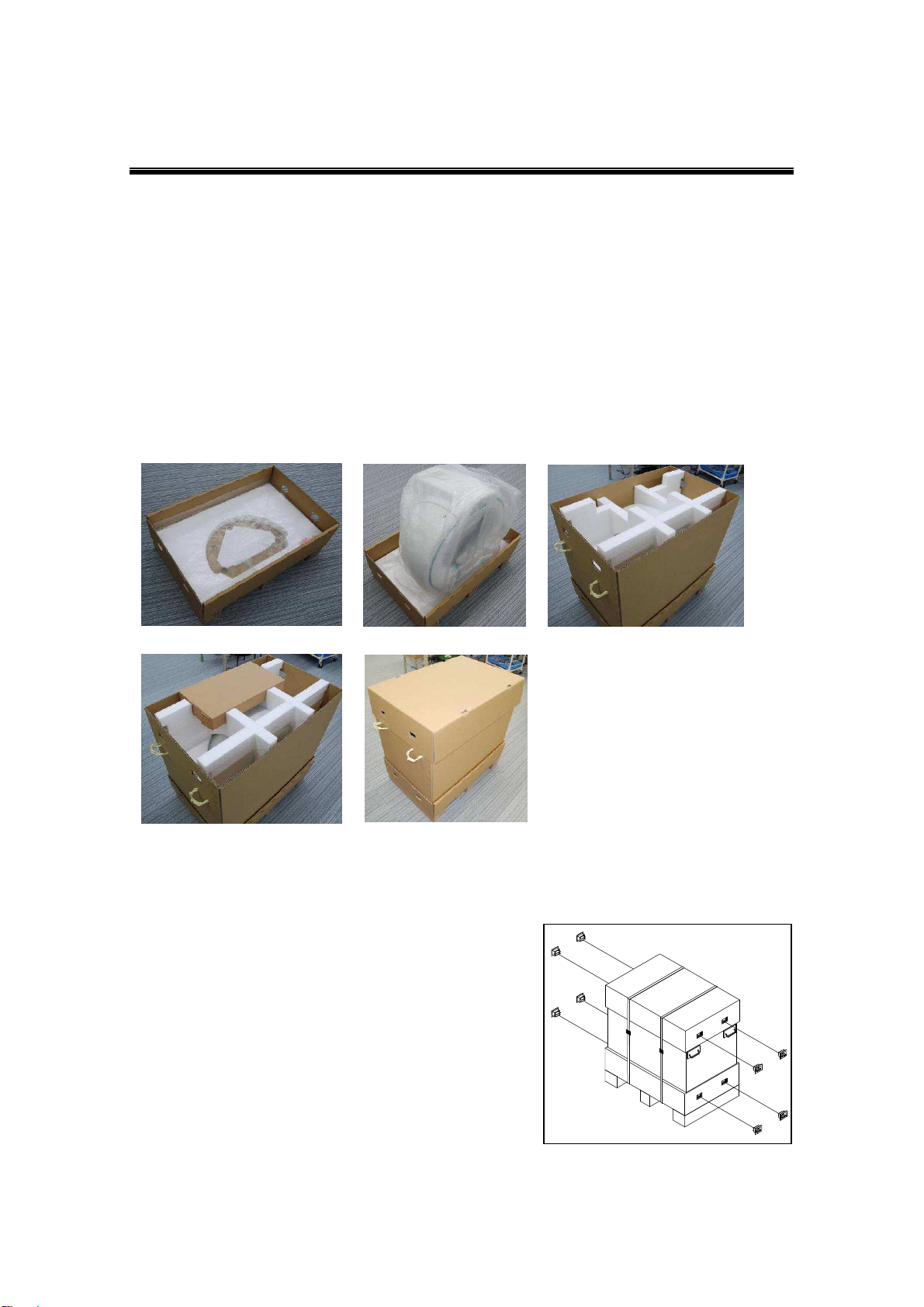
1. Packaging ..................................................................................................... 2
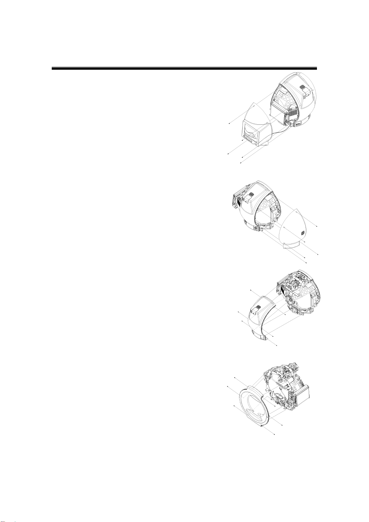
2. Removing Cover........................................................................................... 3
3. Replacing Parts ............................................................................................ 4
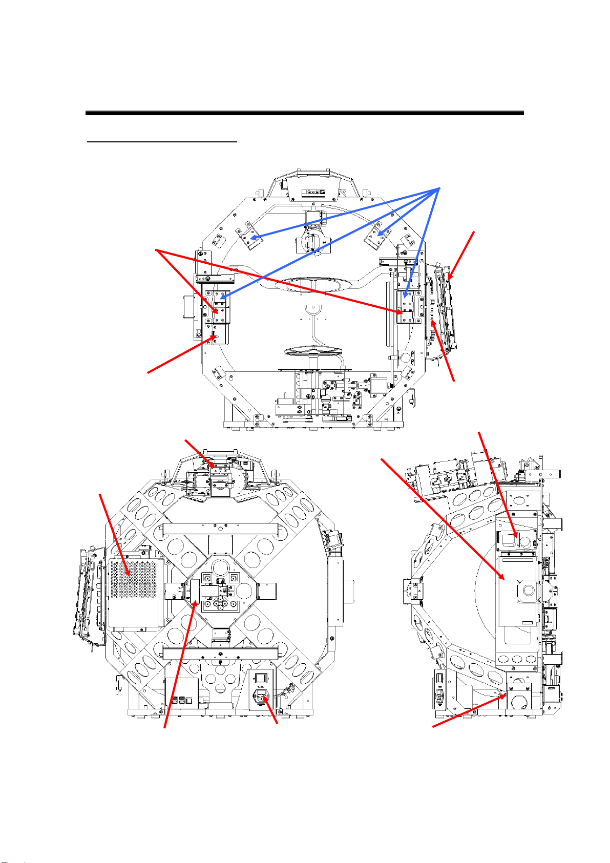
General views (internal)..........................................................................................................4
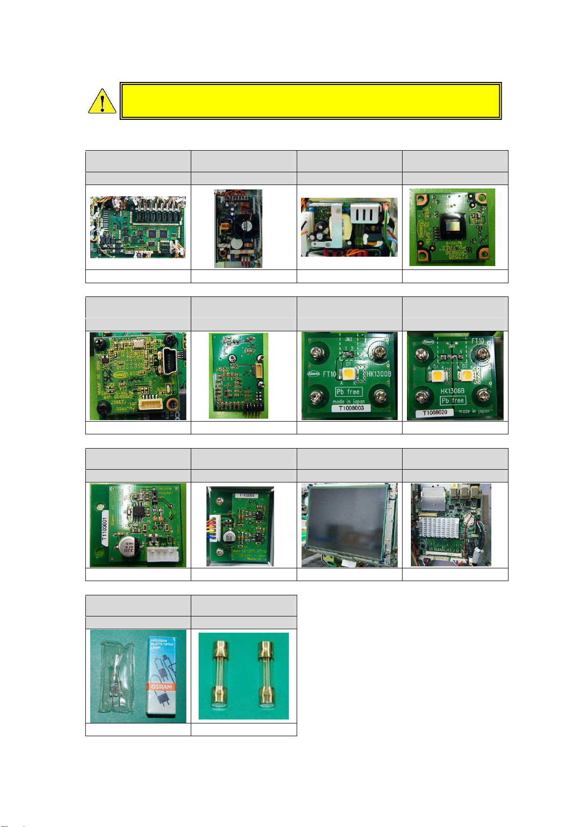
―Replacement parts list―.....................................................................................................5
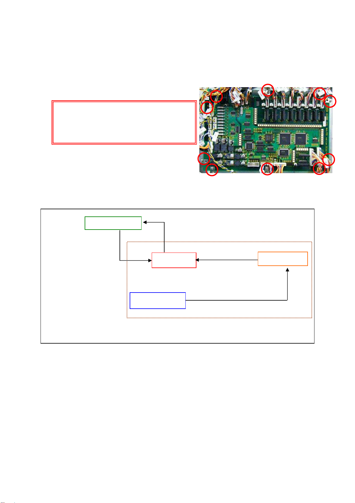
―Replacing main board―......................................................................................................6
―Initial data processing―.....................................................................................................6
―Replacing switching power supplies―.............................................................................7
―Replacing camera―.............................................................................................................8
―Replacing stimulus intensity sensor―..............................................................................9
―Replacing background intensity sensor―........................................................................9
―Replacing speaker―..........................................................................................................10
―Replacing board PC―.......................................................................................................10
―Replacing monitor―.......................................................................................................... 11
―Replacing stimulus lamp―...............................................................................................12
―Replacing background LEDs―........................................................................................13
―Replacing fuses―..............................................................................................................14
4. Error Messages and Corrective Actions .................................................. 15
5. Cleaning Optical System and Adjusting Mirror ....................................... 20
―Cleaning lens in section A―.............................................................................................20
―Cleaning lenses in section B―........................................................................................21
―Cleaning section C―.........................................................................................................22
―Cleaning other parts―.......................................................................................................23
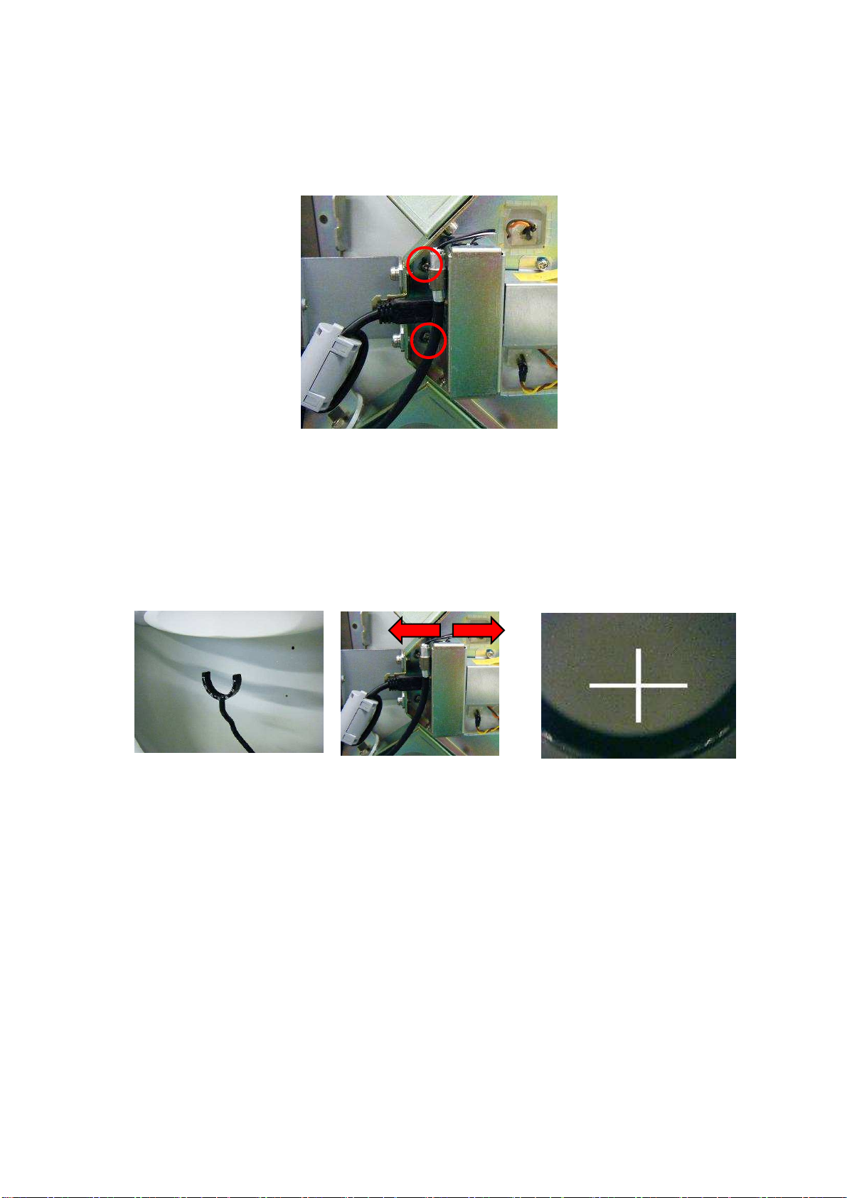
―Adjusting mirror―.............................................................................................................24
6. Using Jig Software ..................................................................................... 26
6-1. Overview..........................................................................................................................26
6-2. Starting and Exiting........................................................................................................27
6-3 Description of Menus......................................................................................................30
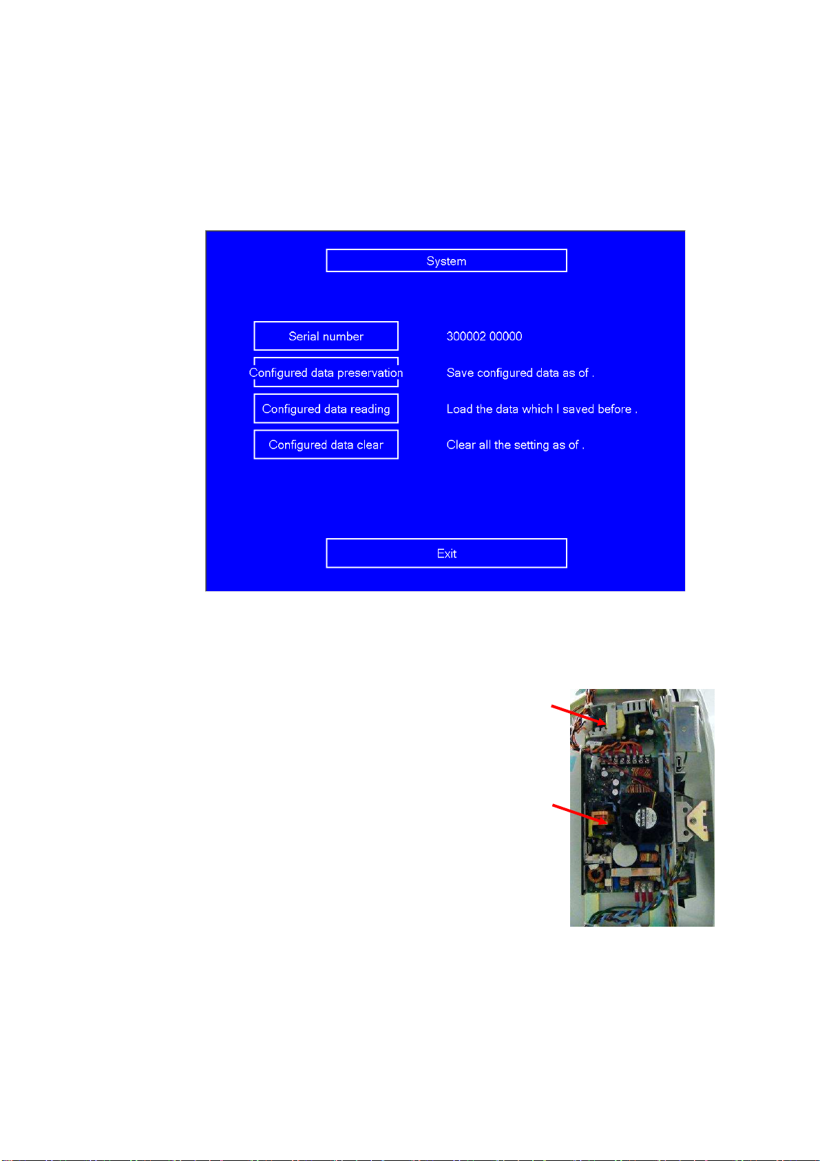
6-4 System..............................................................................................................................54
7. Wiring Diagram........................................................................................... 56

GG-11008 Edition 1.2
- 2 -
1. Packaging
(1) Place bubble wrap on the bottom
Place a sheet of bubble wrap of approximately 520mm×780mm on the bottom of the packing
carton (Figure 1).
(2) Cover the main unit with a bubble wrap bag and put it in the packing carton
Cover the main unit with a bubble wrap bag and put it in the packing carton prepared in step
(1) above (Figure 2).
(3) Outer sleeve and top pad
Put outer sleeve and top pad on the main unit (Figure 3).
(4) Accessory box
Put the accessory box into the top pad (Figure 4).
(5) Top cover
Place the top cover on the packing carton (Figure 5).
(6) Mount fasteners and bind with polypropylene bands
Mount two fasteners to the packing carton and bind it with polypropylene bands (Figure 6).
Figure 6
Figure 1
Figure 2
Figure 3
Figure 4
Figure 5

GG-11008 Edition 1.2
- 3 -
Figure 7
Figure 8
Figure 10
Figure 9
2. Removing Cover
(1) Remove the right-side cover
Remove five screws and remove the cover.
Be careful of #9530 connected through the harness (Figure 7).
(2) Remove the left-side cover
Remove five screws and remove the cover (Figure 8).
(3) Remove the center cover
Remove six screws and remove the cover (Figure 9).
(4) Remove the front cover
Remove six screws and remove the cover (Figure 10).

GG-11008 Edition 1.2
- 4 -
3. Replacing Parts
General views (internal)
*For details, see the replacement parts list.
Background
intensity sensor Main board
Background
LEDs (white)
Monitor
Background LEDs (yellow)
Stimulus intensity sensor
Stimulus lamp
Board PC
Fuses
Switching power supply (1)
Camera boards (1), (2) and (3)
Switching power supply
(2)

GG-11008 Edition 1.2
- 5 -
―Replacement parts list―
Main board Switching power
supply (1) Switching power
supply (2) Camera board (1)
FT10_9510 PM201-12B PM60-12A SC36MF1_1210
P.6 P.7 P.7 P.8
Camera board (2) Camera board (3) Background LED
(white) Background LED
(yellow)
SC36MF1_1230 FT10_1337 FT10_9580 FT10_9581
P.8 P.8 P.13 P.13
Stimulus intensity
sensor Background intensity
sensor Monitor Board PC
FT10_9540 FT10_9610 CR121DXL19C1 MX-4020
P.9 P.9 P.11 P.10
Stimulus lamp
(halogen lamp) Fuses
OSRAM 64602 021806.3
P.12 P.14
Before replacing parts, be sure to switch the main unit power OFF and
disconnect the power cable from the receptacle outlet.

GG-11008 Edition 1.2
- 6 -
Note:
The main board holds the initial data.
So, data must be reset after replacing
the main board. Be sure to perform
initial data processing in the procedure
given below.
―Replacing main board―
When replacing the main board (FT10_9510), disconnect cables from connectors, loose 10
screws and remove the board (Figure 11). After replacing the main board, be sure to reconnect
the cables to the right destinations (see the wiring diagram).
―Initial data processing―
The initial data (FTflash.ini) is processed as shown in Figure 12.
FT10 board PC
When the software is started
with the FT10 board PC
connected, the initial data is
read from the board and
overwritten.
Written to board after adjustment with jig software
FT10 main board
FTflash.ini
FTflashTmp.ini
Jig software
Adjusted data is reflected to FTflash.ini
Initial data
Reflected as data being adjusted
Temporary data being adjusted with jig software
Figure 12
Figure 11

GG-11008 Edition 1.2
- 7 -
Rewriting data
Start the AP-7000 jig mode with the main board mounted.
Select [Hardware setting]→[System] and select [Configured data preservation] (Figure 13 (1)) to
create FTflashTmp.ini.
After replacing the main board, select [Configured data reading] (Figure 13 (2)) in jig mode,
select [Save and Exit] and start AP-7000.
―Replacing switching power supplies―
There are two switching power supplies (A and B), which are
mounted to the left side viewed from the chin rest of the main unit
(Figure 14).
When replacing switching power supply A, loosen three screws.
The support is not fixed, so be careful not to lose it. When
replacing switching power supply B, loosen four screws of (1),
remove the power supply unit together with switching power supply
B, and loosen four screws that fix it from backside.After
replacement, be sure to reconnect the cables to the right
destinations (see the wiring diagram).
Figure 14
A
B
(1)
Figure 13
(2)

GG-11008 Edition 1.2
- 8 -
―Replacing camera―
(1) Disconnect the cable, loosen screws and remove the camera
Disconnect the cable, loosen two screws and remove the camera unit (Figure 15).
(2) Adjust the camera
After replacing the camera, temporarily fix it because adjustment is required. Switch the main
unit power (be careful of electric shock) and move the camera back and forth for focusing
while viewing the monitor. When focusing, lift the lens frame, put a finger or another object
(Figure 16) or paste a piece of paper written with a letter, etc. Then, move the unit right and
left and stop it at the position of the best focus (Figure 17). After that, fine-tune the mirror
placed in front of the camera so that the cross-hair cursor of the camera is positioned at the
horizontal center of R of the lens holder (Figure 18).
Figure 15
Figure 16 Figure 18Figure 17

GG-11008 Edition 1.2
- 9 -
―Replacing stimulus intensity sensor―
(1) Remove the stimulus intensity sensor together with its supporting plate
The stimulus intensity sensor is positioned under the left dome
viewed from the chin rest side. Remove the stimulus intensity
sensor connector, loosen two screws of the bottom plate, and
remove the unit (Figure 19).
(2) Remove the stimulus intensity sensor from the supporting plate
Loosen two screws of the supporting plate and remove the stimulus
intensity sensor (Figure 20).
(3) Mount and adjust the stimulus intensity sensor
Mount the stimulus intensity sensor by reversing steps (1) and (2) above. Before fixing the
supporting plate, align the supporting plate with its vertical stroke so that it is positioned in
the vicinity of the center of the dome hole and fix it. Then, align the stimulus so that the
amount of light on the acceptance surface becomes the highest level. (For details, see
Section 6 "Using Jig Software" on page 25.)
―Replacing background intensity sensor―
(1) Remove the background intensity sensor
The background intensity sensor is mounted under the
background LED viewed from the chin rest side.
First, disconnect the background intensity sensor connector,
loosen two screws and remove the sensor together with its
supporting plate (Figure 21).
(2) Mount and adjust background intensity sensor
Mount the background intensity sensor by reversing the removing steps. The board itself
needs no adjustment, but adjustment for recognizing the new sensor values is required. (For
details, see Section 6 "Using Jig Software" on page 25.)
Figure 21
Figure 19
Figure 20

GG-11008 Edition 1.2
- 10 -
―Replacing speaker―
(1) Remove the speaker
The speaker is positioned on the upper-right side viewed
from the chin rest. Disconnect the connector connected to the
board PC, loosen two screws and remove the fixing plate
(Figure 22).
―Replacing board PC―
(1) Remove the board PC
The board PC is positioned on the right side viewed from the monitor. Loosen three screws
fixing the board PC cover and remove it (Figure 23). Disconnect all connected connectors,
loosen four screws and move the board PC (Figure 24).
(2) Mount the board PC
Fix the board PC with screws and connect the connectors.
Figure 23
Figure 22
Figure 24

GG-11008 Edition 1.2
- 11 -
―Replacing monitor―
(1) Remove the monitor unit
The monitor unit is positioned on the right side viewed from the chin rest. Remove the
connector from the board (Figure 25) on the rear side of the monitor unit, loosen four screws
and remove the monitor unit (Figure 26). Remove four screws from the monitor and remove
the L-shaped brackets from the monitor.
(2) Mount the monitor unit
Mount the L-shaped brackets to the monitor and mount the monitor unit. Connect the
connector to the board on the rear side of the monitor unit.
Figure 26Figure 25

GG-11008 Edition 1.2
- 12 -
Figure 30
―Replacing stimulus lamp―
(1) Open the cover
Turn the stud counterclockwise with a slotted screwdriver and remove the stimulus lamp
cover (Figure 27).
(2) Remove the bracket
Hold your hand close to the lamp unit to check that it is not hot and remove the connector
(Figure 28). Loosen the screw above the stimulus lamp and lift the lamp unit (Figure 29).
(3) Replace the lamp
Pull out the stimulus lamp and insert a new lamp. When handling the new lamp, use gloves
and do not directly touch the glass part of the lamp with your fingers (Figure 30). If
fingerprints are put on the lamp, wipe them off.
Figure 27
Stud
Figure 28 Figure 29
Before replacing the lamp, be
sure to switch the main unit power
OFF and disconnect the power cable from the receptacle outlet.
Wait approximately 20 minutes, check that the lamp is cooled and
start the lamp replacement.

GG-11008 Edition 1.2
- 13 -
―Replacing background LEDs―
(1) Remove the front cover
See Section 2 "Removing Cover."
(2) Replace the background LED unit
Disconnect the connectors from the background LEDs, loosen two screws and remove the
background LED unit (Figure 31). Loosen two screws, remove the base, loosen four screws
holding the board and remove the board (Figure 32). For the LED colors, see Figure 33.
Figure 31 Figure 32
Before replacing t
he lamp, be sure to switch the main unit power OFF
and disconnect the power cable from the receptacle outlet. Wait
approximately 20 minutes, check that the lamp is cooled and start the
lamp replacement.
Figure 33
Background
LEDs (white)
Background LEDs (yellow)

GG-11008 Edition 1.2
- 14 -
―Replacing fuses―
(1) Remove the fuse case
Disconnect the power cable and, using a slotted screwdriver, pull the AC inlet fuse case to
this side to remove it (Figures 34 and 35).
(2) Replace the fuses
Replace the fuses and put the fuse case into the AC inlet (Figure 36).
Figure 35Figure 34
Figure 36

GG-11008 Edition 1.2
- 15 -
4. Error Messages and Corrective Actions
FT10 software error messages and related corrective actions are given below.
Starting and exiting
Messages Causes and corrective actions
Please make the room dark The background intensity cannot be set. The room may be
too bright, so darken the room. If th
e setting is still disabled,
see “Cannot set the background intensity" and "Lamp
replacement or service call”.
[OK] Resets the intensity. Darken the room, press
[OK] and set the intensity again.
[Cancel] Terminates the initialization without setting the
intensity and returns to the base menu screen.
To resume the initial check, once close the
software and switch the main unit power OFF,
resolve the problem, and then restart AP-7000.
No Database file
Please confirm the data drive and
the network, etc
Leave the message on the left being displayed. First,
confirm that the network components (LAN cable, hubs,
etc.) are surely connected and normally operating to
establish a healthy network. Next, confirm that a personal
computer, hard disk drive, USB flash drive, etc. specified
as the data save destination are surely connected and
normally operating. If any of those components is not
correctly connected or normally operating, restore the
normal state and then, select [Search again] in the
message dialog box.
If you are not sure about the cause, select [Cancel], check
the network environment and data save destination, and
then, restart the instrument.
If no abnormality is found in the network environment and
data save destination or the same message still appears
after removal of the abnormality, contact Kowa or your
Kowa dealer.
No serial communications
available. Communication error has occurred inside the instrument.
Contact Kowa or your Kowa dealer.
Cannot open the database Data drive error.
Contact Kowa or your Kowa dealer.
Initializing KOWAAP-7000... Wait
for a while with a cup of coffee. Initialization is being performed. Wait for a moment. If the
input screen does
not open after waiting 5 minutes or more,
switch the power OFF and ON.
Cannot initialize the motor The motor cannot be initialized. Switch the power OFF and
ON. If this message still appears, contact Kowa or your
Kowa dealer.
Motor error (motor name) Motor or motor's sensor error.
Contact Kowa or your Kowa dealer.

GG-11008 Edition 1.2
- 16 -
Messages Causes and corrective actions
Cannot set the stimulus intensity ・A head band can be obstructing the sensor in the dome.
Take the head band out of the dome, and restart the
instrument.
・Sometimes dust attaches to the sensor in the dome.
Confirm the dust at the sensor in the dome.
Remove the dust out of the dome, and restart the
instrument.
・If nothing is obstructing the sensor, the intensity of the
projection lamp is reduced. If the lamp is lit, it is not
necessary to replace it immediately. However, it is
recommended to replace the lamp as soon as possible.
・If the projection lamp is off, immediately replace it with a
new one.
・If the same message still appears after lamp replacement,
the possible causes include dirt on the sensor and/or lens
and disconnected lines. Contact Kowa or your Kowa dealer.
Darken the room The dome intensity cannot be set. The room may be too
bright, so darken the room and press OK.
Confirm the date.
Date [-××- : ]
When the date is not correct
Check the current date and time being displayed.
If the current date and time are incorrect, press [Date] to
open the date setting dialog, and then set the correct date
and time.
Even if the current date and time are correct, this message
may appear when the power is turned on immediately after
it is turned off.
Can not run camera viewer
Camera for eye fixation monitoring has an error. Restart the
instrument. If the same message still appears after the
restart, contact Kowa or your Kowa dealer.
Can not back up
The Archive drive data is larger
than the Data drive data. Please
make sure that the Data and
Archive data are being saved to
the correct destination.
Check for the current data save destination and data
content.
If there is no problem with the data save destination and
data content, change the backup media or backup
destination.
The remained memory of the drive
is less than 5% This message appears when the remaining free space of
the data save drive is less than 5 % at the time of KOWAAP
–7000 startup or search result save.
Cannot set the background
intensity The head band may be blocking the sensor in the dome.
Take the head band out of the dome and restart AP-7000.
If this message still appears after restarting, contact our
sales agency.

GG-11008 Edition 1.2
- 17 -
Entry screen
Messages Causes and corrective actions
The ID is not entered
The date of birth is not entered
Part of the date of birth is not
entered
The ID and the date of birth are
not entered. Input again.
[Search] has been pressed with ID and Date of birth left
blank or incomplete on the input screen. Properly input the
ID and Date of birth on the input screen.
If “Prohibit NoID” is set to OFF in the Configuration dialog,
you can press [Cancel] to proceed with the examination.
However, in this case, the quality of the examination will be
reduced and some analysis functions will be unavailable.
Delete the selected data?
Delete all data of the selected
ID?
[Delete] has been pressed to del
ete the examination results
from the patient ID list or all lists selected in the dialog
opened by [Open List]. Press [OK] to delete or [Cancel] not
to delete.
Axis is not entered ・
[OK] has been pressed with Cyl (Cylindrical diopter power)
input and Axis (Axis degree) not input in the Correction
value input dialog for the patient information.
・Input a value to the Axis input box or clear the value in the
Cyl input box, and press [OK].
Cyl is not entered ・[OK] has been pressed with Axis (Axis power) input and
Cyl (Cylindrical diopter degree) not input in the Correction
value input dialog for the patient information.
・Input a value to the Cyl input box or clear the value in the
Axis input box, and press [OK].
The image is broken. Cannot
display.
There is insufficient memory for
displaying the image
This is not displayable bmp
format
Cannot assign the bitmap
memory
The image file selected to set a fundus image on the input
screen cannot be read. Select other image file.
Reactivate the application to set it
effectively Settings have been made to link up with a card reader or
filing system KOWA VK Series. Restart the instrument to
allow the changed settings to take effect.

GG-11008 Edition 1.2
- 18 -
Examination screen
Messages Causes and corrective actions
Darken the room The room is deemed to be too bright to perform an
examination. Adjust the luminance of the room to be the
same as that when the instrument is started.
Can not recognize the patient's
eye. Please make sure that the
chin is placed correctly on the chin
rest.
Do you want to manually select the
patient's eye?
[Start] has been pressed when the patient’s chin does not
yet come into contact with the chin rest. Confirm that the
patient’s chin is surely placed on the chin rest.
Press [OK] to manually specify the eye to be examined.
Press [Cancel] to close the message box.
Failed to acquire the pupil position
Do you wish to proceed with
acquisition from the beginning?
You have failed in gaze monitor setting.
Pupil position acquisition failure can be caused by
eyelashes, eyelid ptosis, opacity of the middle translucency
body, and small pupil.
To retry the acquisition, confirm the eye fixation, and then
press [OK]. Not to retry it, press [Cancel].
If you press [Cancel], the gaze monitor function will be
deactivated for this examination.
The fovea is examined first.
The fixation target is the 4 points at
the lower center.
[Start] has been pressed on the examination screen at the
time of examination startup with the fovea examination set
to ON. The fixation target is automatically moved to 4 points
at the lower center. Press [OK] to start the fovea
examination.
Next, the threshold examination
starts
(Next, the isopter examination
starts)
The fixation target is the selected
one
Fovea examination has been completed with the fovea
examination set to ON. The fixation target is automatically
returned to the original location. Press [OK] to start the
threshold (isopter) examination.
Put back the lens frame. This message appears when the lens holder is set for the
periphery examination (more than 30°
) or upon completion
of center examination with the lens holder set in the
program consisting of both center (within 30°) and
periphery examinations. Thus, be sure to fold the lens
holder backward.
In the program consisting of both center and periphery
examinations, the stimulus is normally presented in random
order. However, when the lens holder is set, the periphery
examination is carried out upon completion of the center
examination. Therefore, this message appears after the
center examination is completed.
Please switch eyes Attempt has been made to re–test an eye other than the
one examined previously. Check the eye to be examined:
left or right.
Select the point examined again [OK] has been pressed without examined points selected
for re–testing. Select points to be re–tested.

GG-11008 Edition 1.2
- 19 -
Messages Causes and corrective actions
Next, the screening examination
starts
(Next, the threshold examination
starts)
Isopter examination has been completed during the Isopter
+ Screening (threshold) examination program. Press [OK]
to start the screening (threshold) examination.
The examined eye is incompatible
with the fundus image During perimetry coordinate setting on a fundus image for
the fundus perimetry, the positions of the fovea and opti
disc have been reversed in comparison to the actual
examined eye. Check whether the examined eye matches
the fundus image. In addition, check whether the examined
eye is left or right.
Maximum number of isopters
reached Attempt has been made to start the Isopter –Manual
examination with 6 types of stimulus. Up to 5 types of
stimulus can be selected for an isopter examination. To
perform an examination with 6 or more types of stimulus,
complete one examination with some types of stimulus
once, and then, perform another examination with the other
types of stimulus.
Result screen
Messages Causes and corrective actions
The combined data is not saved.
Continue operation? Attempt has been made to change over the screen to
another without saving the result of data combination. To
save the combined data, press [Cancel] and [Save] in this
order. Not to save, press [OK] and proceed with the
operation.
The data has been properly copied
Data read has been normally completed from Kowa
automatic perimeter “AP–6000,”“AP–5000,”or “AP–
3000”to “AP–7000.”
The remained memory of the drive
is less than 5% This message appears when the remaining free space of
the data save drive is less than 5 at the time of software
startup or examination result save.
Database/network errors
Messages Causes and corrective actions
Network connection error
Network drive has been shut
down.
Could not connect to the network
If you proceed there will be no
link to the VK (any) database.
Cannot open the database
If the examination continues, the
results will be saved in the local
folder separately from previous
data.
The database or network is abnormal in some way. Select
[OK] to save the data locally. If the database or network is
restored when the instrument is started next time, the
locally saved data can be coupled to the conventional data.
Select [Cancel] to end KOWAAP–7000.
Other manuals for AP-7000
1
Table of contents
Other Kowa Medical Equipment manuals
Popular Medical Equipment manuals by other brands

Storz
Storz XENON NOVA 175 instruction manual

Ambu
Ambu aBox 2 Replacement manual

Fahl
Fahl OPTIFLAUSCH SLIM K PED Instructions for use

TASKA Prosthetics
TASKA Prosthetics TASKA-XXXXXX Appropriate Use Guidelines

DHG
DHG RoMedic LowBackSling Instructions for use

Stryker
Stryker Power-PRO XT 6500 Operation & maintenance manual

Siemens
Siemens PELTON & CRANE Light Fantastic II installation instructions

Barco
Barco Coronis 5MP Mammo System manual

Masimo
Masimo iSpO2 Operator's manual

Blackrock Microsystems
Blackrock Microsystems NeuroPort 6221 user manual

bort medical
bort medical Generation 215 850 Instructions for use

NOVAFON
NOVAFON Pro user manual