Kowa AP-7000 User manual

INSTRUCTION MANUAL
US


1
Introduction
Congratulations on your purchase of KOWA AP–7000.
KOWA AP–7000 is an automatic perimeter intended for measurement of the visual field.
This manual provides a description of the operating procedures of the KOWA AP–7000 and the precautions to be
observed during its use. Please read this manual carefully to assure that the instrument can demonstrate its full
capabilities and work safely. After you have finished reading, keep this manual in an easily accessible location near the
instrument for future reference.
Safety precautions
This manual describes important precautions to be observed when you use this system to assure that the system is
used safely without causing any damage to the human body or property of the purchaser and other persons.
The designations and pictorial symbols used in this manual are described in the table below.
These should be fully comprehended before reading the text of this manual.
This document does not include any information about replacement or repair of parts other than consumables. For
details about the replacement or repair of parts, see the Service Manual.
Meanings of designations
Warning
Improper operation of this instrument may incur a risk of causing death or serious
injury.
Caution
Improper operation of this instrument may result in bodily injury*1or damage to
property*2.
Descriptions you must read.
Describes items you should observe or pay close attention to during operation of this
instrument.
*1A bodily injury means an injury, burn, electrical shock and so forth that will not necessitate hospitalization or long –term
outpatient treatment.
*2Damage to property means an extensive damage to a house and/or household goods as well as a domestic animal and pet.
Meanings of symbols
Graphical indication of any danger (including warning and caution).
What is warned is explicitly and pictorially indicated by a picture or its associated
message on or near a pictorial symbol.
Graphical indication of prohibited operation (prohibitive item).
What is prohibited is explicitly and pictorially indicated by a picture or its associated
message on or near a pictorial symbol.
●
Graphical indication of any mandatory action (obligatory item).
What must always be done is explicitly and pictorially indicated by a picture or its
associated message on or near a pictorial symbol.
Disclaimer
Kowa is not responsible for:
Any damage caused by fire, earthquake, third party’s action, any other accident or user’s intentional or unintentional error, abuse
or use under abnormal conditions.
Any damage resulting from use of the product or its malfunction (e.g. operating loss, shutdown, change/loss of stored data and so
forth).
Any damage resulting from disregarding what is described in this manual.
Any damage resulting from, for instance, malfunctioning of instrument caused by a combination of connected devices.

2
Warning
Unplug
If any abnormal smell, sound, overheating or smoke should be detected, be sure to turn
OFF the main power immediately and then unplug the instrument from the power outlet.
Continued use of the instrument may cause the instrument to malfunction or cause a fire.
Contact Kowa or your Kowa dealer for inspection.
Warning
High–Voltage
When replacing the projection lamp and the fuse, make sure the main
power is turned OFF and then unplugged from the power outlet. Wait for
more than 10 minutes, or more than 10 minutes if immediately after use,
before replacing. Otherwise, there may occur electrical shock or burn.
When replacing the fuse, make sure the main power is turned OFF and
then unplugged from the power outlet. If the fuse holder cover is removed
without the instrument unplugged, there may occur electrical shock or burn.
Obligatory
Use a designated fuse only. Using an undesignated fuse may cause the instrument to
malfunction or cause a fire.
Warning
High–Voltage
Be sure to plug into the power outlet completely and securely. Otherwise
there may cause a fire or electrical shock.
Make sure the instrument is properly grounded to prevent bodily injuries.
Connect the plug into the three –wire grounding type outlet with ground
wire. Otherwise, there may occur electrical shock.
Regularly remove dust on the power plug. Dust accumulated on the power
plug may absorb moisture, which may result in isolation failure and cause a
fire.
Prohibitory
Do not load the power outlet or cable with excess of its rated capacity.
If the main power supply cable should share a power outlet with other
devices and the rated capacity is exceeded, there may cause a fire or electrical shock.
The air vent shown must not be obstructed.
Obstructing the air vent may increase the internal temperature resulting in malfunction of
the instrument or a fire.
Do not insert any metal object into an air vent or opening of the instrument. It may cause
electrical shock, a fire, or malfunctioning of the instrument.
Do not place the instrument close to wall, Because it is too difficult to remove the power
supply cable from AC inlet.
Do not push the instrument. It may fall down to cause a failure or an injury.
Warning
High–Voltage
Do not place a container or cup containing liquid near the instrument.
Spilled liquid entering into the instrument may cause electrical shock.
If liquid should be spilled into the instrument, turn OFF the main power
immediately, unplug the instrument from the power outlet, and then contact
Kowa or your Kowa dealer for inspection.
Do not plug or unplug the power supply cable with wet hand.
Otherwise, there may occur electrical shock.
Disassembly
prohibited
Do not disassemble, modify or repair the instrument yourself.
It may cause a fire, electrical shock, bodily injury, or instrument malfunctioning.
Refer all servicing to Kowa or your Kowa dealer.
The instrument modified or repaired by anyone other than a Kowa designated repair facility
will void the warranty.

Introduction
3
Caution
Obligatory
The power supply must be provided for the sole use of this instrument.
Sharing the same power supply with other external devices may cause instrument
malfunctioning.
Be sure to prevent the instrument from being operated by anyone other than the following
certified personnel:
・MD (Ophthalmologist), ophthalmology resident
・Nurse, vocational nurse
・Orthoptist, Optometrist
When operating the instrument, use caution so that the patient’s face or hand does not
come in contact with the parts of the instrument. Otherwise, it may cause a bodily injury.
When operating the instrument, use caution so that the patient’s face does not touch the
end of the instrument. Otherwise, it may cause a bodily injury.
A patient with the smaller head may get his or her head caught between the components.
Handle the projection lamp and the fuse with caution. Otherwise, glass components may be
damaged, resulting in a bodily injury.
Prohibitory
Do not pull the power supply cable when unplugging the instrument from the power outlet.
Doing so may damage the cable and cause a fire or electrical shock. Be sure to hold the
plug when unplugging.
Do not install the instrument at unstable location such as on a shaky base or a tilting
surface.
Doing so may cause the instrument do to drop or fall over and result in a bodily injury.
Caution
High–temperature
Do not replace the projection lamp immediately after turning OFF the main
power. You could be burned by a lamp heated to a high temperature.
Wait for more than about 30 minutes to cool the lamp down before replacing.
Do not touch the projection lamp bulbs with your bare hand.
Otherwise, the lamp may reduce the light intensity or operating life.
Keep your fingers off the location of the chin rest and the under the chin rest’s cover.
When the chin rest moving, the fingers may be pinched and injured.
Do not wipe the outer surface of the instrument with solvents such as benzene, organic
solvent, and ether. Doing so may cause discoloration or degradation.
For the operator, do not touch the following connectors and patient simultaneously:
・Response button jack
・USB connecter
・Ethernet connecter
Do not use a sharp object to perform touch operation on the touch panel.
Otherwise, It may cause instrument malfunctioning.
Do not apply excessive force to the touch panel.
Otherwise, It may cause a failure or an injury.

4
Meanings of symbols

Introduction
5
Symbol mark
Symbol for “Type B applied part”.
Symbol for “Power ON”.
Symbol for “Power OFF”.
Symbol for instrument status (Power ON or Standby)
Symbol for “Response button jack”
Symbol for “Reference the instruction manual”
Symbol for “Pushing prohibited”.
Symbol for “Warning”or “Caution”.
Symbol for “Warning High–voltage”.
Symbol for “Caution High–temperature”.

6
Operating precautions
1. Operating environment
1) Be sure to prevent the instrument from being operated by anyone other than the following certified personnel:
・MD (Ophthalmologist), ophthalmology resident
・Nurse, vocational nurse
・Orthoptist, Optometrist
2) Handle the instrument with care, and do not apply strong shock to the instrument. Avoid placing any object
on the instrument.
3) Avoid high temperature and humidity, direct sunlight, and dust when installing and storing the instrument.
Strictly observe the following environmental conditions.
Operating
Transporting and storing
Environmental temperature
10 to 35 ℃
–15 to +60 ℃
Relative humidit y
30 to 90 %
10 to 95 %
4) Avoid condensation when using, transporting or storing the instrument.
5) Place this instrument in a darkroom or a room of which luminance can be reduced as low as a darkroom.
6) When operating the touch panel, be sure to use the input pen included with this instrument.
7) When housing the lens holder, fold it backward, and then to the left side. If you fold the lens holder to the left
without folding backward, it may come into contact with the exterior of the instrument. Use great care.
8) When cleaning the head rest, chin rest, response button, and head band, wipe with rubbing alcohol. Do not
sterilize them.
9) Do not install any software other than the KOWA AP–7000 accessory software in this instrument. Otherwise,
the instrument may be caused to malfunction. Kowa will not be liable for malfunction of the instrument
caused by installation or execution of such extra software.
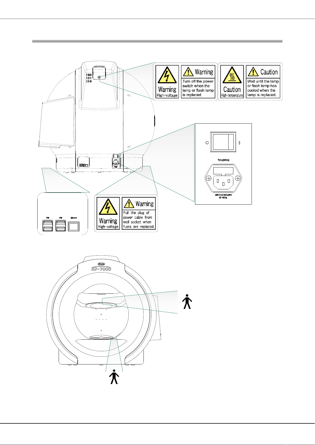
10) Be sure to follow the procedure when terminating the instrument (See “4.1 Switching on and off the
instrument”). Do not turn off the power switch when the touch panel is showing a black screen without any
data shown or with “It is now safe to turn off your computer” appearing, otherwise it may cause a failure or
data loss. In this case, Kowa will not be liable for any failure or data loss.
11) In part of the image display area of the KOWA AP–7000 software, ifjpeg.spi (in the NiftyServeFGALAV
library) is used as a jpeg plug –in with permission from Mr. Yoshihito Takemura.
2. Precautions for electric system
1) The power supply must be provided for the sole use of this instrument. Sharing the same power supply with
other external devices may cause the instrument to malfunction.
2) When the instrument will not be used for a long period of time, turn off the power switch and disconnect the
power plug from the outlet. Otherwise, a fire may start.
3) Use great care to select an installation location of the instrument so that the power plug will not be
disconnected during operation of the instrument. In the event the plug is disconnected during operation, be
sure to turn off the power switch, and then insert the plug to the outlet.
4) Kowa is not liable for malfunctions and/or damages resulting from maintenance and/or repairs performed by
the third party other than an agent authorized by Kowa.
5) Kowa is not liable for malfunctions and/or damages resulting from maintenance and/or repairs using parts
other than repair parts specified by Kowa.
6) Be sure to connect the instrument to the specified power source (AC100–230V, 50/60Hz).
7) The input voltage should always be maintained within ± 10% of the rated voltage.
8) This instrument is floor –standing type (not intended for moving). When it is necessary to move the
instrument, contact Kowa or your Kowa dealer.
9) Turn off the power switch before connecting the instrument to an external device or connecting/disconnecting
the power plug to/from the outlet.
10) Before turning off the power switch, be sure to follow this document. Do not turn off the power switch when
the touch panel is showing a black screen without any data shown or with “It is now safe to turn off your
computer” shown, otherwise it may cause a failure or data loss.
3. Precautions for instrument
1) Always cover this instrument with dust cover when not in use in order to protect them.
2) This instrument is floor–standing type (not intended for moving). When it is necessary to move the
instrument, contact Kowa or your Kowa dealer.
4. Disposal precautions
Disposal of this instrument is subject to local waste management and public safety laws and regulations. When
you need to dispose the instrument, comply with the ordinances and regulations of the applicable local
government and ask an authorized industrial waste management contractor for disposal.
5. Prescription Device Caution
For US market
Caution
Federal law restricts this device to sale by or on the order of a Physician or Practitioner.

Introduction
7
Precautions: use of medical electrical system
1. Precautions for use of medical electrical system
1) All components of this medical electrical system may be installed within a limited patient environment (a radius
of 1.5m around a patient) when all components are installed in accordance with the installation instructions
using “Multi –tap with Isolation Transformer”, which is one of the system components.
2) As a prerequisite for installing this system, other components (a personal computer, printer, video capture
printer, video monitor, or other devices) which do not comply with IEC 60601–1 must be powered from “Multi
–tap with Isolation Transformer”. The electric power to these components supplied from an electric source
other than “Multi –tap with Isolation Transformer” (e.g., power outlets) may cause increased enclosure
leakage current or potential difference between protective grounds resulting in the injury to the patient or
operator. Use “Multi –tap with Isolation Transformer” only for supplying the power to components other than
system components.
3) Any medical electrical equipment connected to this system to compose a medical system must comply with
IEC 60601–1.
4) Any non –medical electrical equipment connected to this system to compose a medical system must comply
with safety standards of IEC or ISO provisions applicable to such non –medical electrical equipment.
5) Do not use any additional multi –tap or extension power supply cable other than those Kowa specified to this
system.
6) Power supply to this system or “Multi –tap with Isolation Transformer” must be provided individually. (Do not
route the power supply through other multi –tap to the system or “Multi –tap with Isolation Transformer”.)
7) The power supply cable for electrical equipment composing a medical system must have durability that meets
IEC 60245/ IEC 60227 or higher standards.
8) Assure that the power supply is turned OFF when connecting other devices to the system.
9) Do not turn ON the power supply until all devices are completely connected.
10) Do not place or install the devices and the system components on an unstable or inclined table.
2. Precautions for use of “Multi –tap with Isolation Transformer”
1) Do not place “Multi –tap with Isolation Transformer” directly on the floor. Water droplets during room cleaning
may enter the multi –tap resulting in the component’s failure.
2) The power supply cable to “Multi –tap with Isolation Transformer” must be connected to a power receptacle
with a protective ground terminal equipotential to the protective ground of this instrument.
3) When using a “Multi –tap with Isolation Transformer” receptacle with a protective ground terminal, read the
instructions attached to the receptacle to familiarize yourself with the correct use.
3. Daily maintenance and cleaning
1) System components
Wipe the soiled outer surface with a firmly squeezed dampened soft cloth. Use mild detergent to remove
excessive dirt. Do not use chemicals or solvents such as thinner and benzene. (As the touch panel cover
easily gets scratched, lightly wipe it with a soft cloth such as gauze.)
Refer to the instructions provided with each device for details of device maintenance and cleaning.
2) Power supply cables, connecting cables, and connectors
Visually inspect that all cables have no flaw or damage.
Visually verify that earth leads of all components and protective ground terminals are securely connected.
Disconnect the power supply cables from the power outlet when you do not use the system for a long period
of time.
3) Others
When you add a personal computer to the system for filing purposes, captured images are stored in the hard
disk drive of the personal computer. Back up the data stored in the hard disk drive regularly since hard disk
drives may have a mechanical or electrical failure.

8
Combinations of medical electrical equipment and non–medical electrical equipment
1. Precautions for system
IEC 60601–1–1 “Safety requirements for medical electrical systems” describes the components combination grouped
into various clinical settings. The brief overview of IEC 60601–1–1 is shown below.
Situation No.
Medically used room
Non-
medically
used room
Examples of
possible causes
for exceeding
LEAKAGE
CURRENT limits
Practical means
of compliance
Apply 16.5 in all
situations
Inside the
PATIENT ENVIRONMENT
Outside the
PATIENT
ENVIRONMENT
1
1a Items A and B
are ME
EQUIPMENT
Multiplied
APPLIED PARTS
of the same type
can cause the
total PATIENT
LEAKAGE
CURRENT to
exceed limits See
Note 1.
- Verify total
PATIENT
LEAKAGE
CURRENT
1b Items A and B
are ME
EQUIPMENT
powered via a
MULTIPLE
SOCKET-
OUTLET
Earth conductor of
the MULTIPLE
SOCKET-OUTLET
is broken See also
1a.
- Additional
PROTECTIVE
EARTH
CONNECTION
(for A or B) or,
- Separating
transformer
1c Item A is ME
EQUIPMENT
and B is non-
ME
EQUIPMENT
Due to high
TOUCH
CURRENT of B
- Additional
PROTECTIVE
EARTH
CONNECTION
(for B) or,
- Separating
transformer
(for B)
1d Item A is ME
EQUIPMENT
and B is non-
ME
EQUIPMENT
powered via a
MULTIPLE
SOCKET-
OUTLET
The earth
conductor of the
MULTIPLE
SOCKET-OUTLET
is broken or, Due
to high TOUCH
CURRENT of B
- Additional
PROTECTIVE
EARTH
CONNECTION
(for A or B) or,
- Separating
transformer
1e Item A is ME
EQUIPMENT
powered from
specified
power supply
in item B
Due to high
TOUCH
CURRENT of B
- Additional
PROTECTIVE
EARTH
CONNECTION
(for B) or,
- Separating
transformer
(for B)
1f Item A is ME
EQUIPMENT
powered from
non-ME
EQUIPMENT
power supply
in B
A
IEC 60601
B
IEC 60601
Mains
Plug
Mains
Plug
A
IEC 60601
B
IEC 60601
MULTIPLE SOCKET-OUTLET
A
IEC 60601
B
IEC xxxxx
Mains
Plug
Mains
Plug
A
IEC 60601
B
IEC xxxxx
MULTIPLE SOCKET-OUTLET
A
IEC 60601
B
IEC xxxxx
Mains
Plug
A
IEC 60601
B
IEC xxxxx
DC/AC
Mains
Plug

Introduction
9
Situation No.
Medically used room
Non-
medically
used room
Examples of
possible causes
for exceeding
LEAKAGE
CURRENT limits
Practical means
of compliance
Apply 16.5 in all
situations
Inside the
PATIENT
ENVIRONMENT
Outside the
PATIENT
ENVIRONMENT
2
2a Items A and
B are ME
EQUIPMENT
No causes of
exceeding
LEAKAGE
CURRENT
- No further
measures are
necessary
2b Items A and
Item B are
ME
EQUIPMENT
powered via
a MULTIPLE
SOCKET-
OUTLET
Earth conductor of
the MULTIPLE
SOCKET-OUTLET
is broken
- Additional
PROTECTIVE
EARTH
CONNECTION
(for A or B) or,
- Separating
transformer
2c Item A is ME
EQUIPMENT
and Item B is
non-ME
EQUIPMENT
Due to high
TOUCH
CURRENT of B
See rationale for
16.5.
- Do not use
metal
connector
housing or,
- SEPARATION
DEVICE
2d Item A is ME
EQUIPMENT
and item B is
non-ME
EQUIPMENT
powered via
a MULTIPLE
SOCKET-
OUTLET
The earth
conductor of the
MULTIPLE
SOCKET-OUTLET
is broken
- Additional
PROTECTIVE
EARTH
CONNECTION
(for A or B) or,
- Separating
transformer
3
3a Items A and
B are ME
EQUIPMENT
No causes of
exceeding
LEAKAGE
CURRENT
- No further
measures are
necessary
3b Item A is ME
EQUIPMENT
and item B is
non-ME
EQUIPMENT
Due to high
TOUCH
CURRENT of B
See rationale for
16.5.
- Do not use
metal
connector
housing for
SIGNAL
INPUT/OUTPU
T PART or,
- SEPARATION
DEVICE
3c Item A is ME
EQUIPMENT
and item B in
is ME
EQUIPMENT
or non-ME
EQUIPMENT
a) Potential
difference
between
PROTECTIVE
EARTH
CONNECTION
S of A and B
b) Due to high
TOUCH
CURRENT of B
See rationale for
16.5.
- Additional
PROTECTIVE
EARTH
CONNECTION
for (A), or
- SEPARATION
DEVICE, or
- Do not use
metal
connector
housing in the
PATIENT
ENVIRONMEN
T
NOTE 1. No causes of TOUCH CURRENT or EARTH LEAKAGE CURRENT exceeding limits.
NOTE 2. IEC 60601: MEDICAL ELECTRICAL EQUIPMENT in compliance with IEC 60601.
NOTE 3. IEC xxxxx: Non-medical equipment in compliance with relevant IEC safety standards.
NOTE 4. Separating transformer: see 16.9.2.1.
NOTE 5. If equipment “B”is outside the PATIENT ENVIRONMENT and if equipment “A”is a CLASS II equipment and has
accessible conductive parts connected to the PROTECTIVE EARTH CONNECTON of equipment “B”then additional
safety measures could be necessary, for example: additional protective earth for “B”or separating transformer or
SEPARATION DEVICE.
A
IEC 60601
B
IEC 60601
MULTIPLE SOCKET-OUTLET
A
IEC 60601
B
IEC xxxxx
Mains
Plug
Mains
Plug
A
IEC 60601
B
IEC xxxxx
MULTIPLE SOCKET-OUTLET
A
IEC 60601
B
IEC xxxxx
Mains
Plug
Mains
Plug
Common protective earth
A
IEC 60601
B
IEC 60601
Mains
Plug
Mains
Plug
Common protective earth
A
IEC 60601
B
IEC 60601
or
IEC xxxxx
Mains
Plug
Mains
Plug
Common protective earth
Protective earth with
potential difference
A
IEC 60601
B
IEC 60601
Mains
Plug
Mains
Plug

10
Operational considerations for a hospital grade
electrical instrument (safety and accident prevention)
1. Only qualified personnel should operate this instrument.
2. The following items shall be considered when installing the instrument.
1) Install at a location away from water or accidental splashing.
2) Install at a location which will not be adversely affected by atmospheric pressure, temperature, humidity, ventilation,
sunlight, dust, air containing salt, sulfur and other substances.
3) Take care to guard against tilt, vibration and strong impacts, e.g., during transportation.
4) Instrument must not be installed at locations where chemicals are stored or gasses are generated.
5) Be careful with the radio frequencies, voltages and allowable amperes (power consumption) of the power supply.
6) Properly connect ground wires.
3. The following items shall be considered before using the instrument.
1) Make sure that the instrument activates properly after checking switch contact, polarity, dial setting and so forth.
2) Make sure that the instrument is properly grounded.
3) Make sure that all cables are properly connected and secured.
4) Use of other instruments and appliances on the same power circuit is liable to cause errors and incorrect flash
output resulting in incorrect diagnosis or hazards.
5) External circuits and connectors that may come in direct contact with the patient must be checked frequently for
signs of wear.
4. The following items shall be considered when using the instrument.
1) Be sure to minimize the time and quantity required for diagnosis and treatment.
2) Always assure that the instrument and patient are in good condition.
3) When an abnormality is found on the instrument, take proper measures, for instance, stopping the operation of the
instrument, to assure the patient’s safety.
4) Do not allow the patient to touch any of the instrument controls.
5. The following items shall be considered after using the instrument.
1) Turn OFF the instrument after setting control switches, dials, and so forth to their initial statuses by the specified
procedure.
2) Do not pull on cables for removal because an excessive force is exerted on them.
3) Clean and rearrange accessories, cables, etc.
4) The instrument must be cleaned prior to use.
6. In case of a problem or malfunction, stop the operation and contact Kowa or your Kowa dealer for repair.
7. Instrument shall not be modified.
8. Maintenance
1) Periodically check the instrument and its components for any abnormality.
2) When using the instrument after it has not been used for a while, please check beforehand to assure that it is in
normal condition and operates safely.
9. Be careful of the possibility that incorrect operation may be caused by strong electromagnetic waves.
This instrument is examined based on IEC 60601–1–2:2001. The purpose of this standard is to maintain safety against
dangerous obstacles in typical medical facilities. When this instrument is influenced by another instrument, or when it
affects another instrument, or when there is such fear, please move this instrument and the other apparatus to create a
distance between the instruments. Moreover, if there is an unknown point, please consult our company or an agency
beforehand.

12
Contents
Introduction ......................................................................................... 1
Safety precautions .............................................................................................................................................................1
Meanings of symbols ....................................................................................................................................................... 4
Operating precautions ..................................................................................................................................................... 6
Precautions: use of medical electrical system .......................................................................................................... 7
Operational considerations for hospital grade electrical instrument (safety and accident
prevention) .............................................................................................................................................................. 10
Components and supplies ............................................................................................................................................. 11
Contents .............................................................................................. 12
1. System description .................................................................. 14
1.1. Intended use ........................................................................................................................................................... 14
1.2. Principle of measurement and System overview........................................................................................... 14
1.3. Features ................................................................................................................................................................... 14
1.4. Name and function of each component 15
2. Installation ................................................................................... 20
2.1. Installation...............................................................................................................................................................20
2.2. connecting an external device............................................................................................................................ 21
3. Flow of operations ................................................................... 22
4.
Preparation for examinations
.......................................... 24
4.1. Switching on and off the instrument.................................................................................................................24
4.2. Operations available with the input screen.....................................................................................................27
4.3. Loading patient information by [Open List] ....................................................................................................28
4.4. Patient information input .....................................................................................................................................30
4.5. Loading patient information from the advance entry list.............................................................................38
4.6. Clearing the patient information ........................................................................................................................39
4.7. Setting of Examination Program and Examination Parameter ...................................................................40
4.8. Each Examination Program.................................................................................................................................45
4.9. Perimetry examination fundus images.............................................................................................................57
4.10. Configuration settings..........................................................................................................................................59
4.11. Preparation for patients and alignment of examined eyes ....................................................................... 71
5. Examination ................................................................................ 74
5.1. Operations available with the examination screen........................................................................................74
5.2. Operational procedure in examination .............................................................................................................76
5.3. Programs requiring examination point selection .......................................................................................... 81
5.4. Manual examination ..............................................................................................................................................88
5.5. Fovea threshold examination (Fovea examination) ......................................................................................95
5.6. The eye fixation of a patient................................................................................................................................95
5.7. Gaze monitor...........................................................................................................................................................95
5.8. Examination Reliability.........................................................................................................................................96
6.
Display, Print, and Analysis of Examination
Results
......................................................................................... 97
6.1. Operation available with the result screen ......................................................................................................97
6.2. Examination result switchover and list display..............................................................................................99
6.3. Print......................................................................................................................................................................... 100
6.4. Both eyes............................................................................................................................................................... 101
6.5. Multi ........................................................................................................................................................................ 104
6.6. Analysis of Threshold Examination Result ................................................................................................... 109
6.7
Fundus perimetry examination result display .............................................................................................. 118
6.8. Isopter examination result display .................................................................................................................. 119
6.9. Re–Test................................................................................................................................................................... 121
6.10. Editing of patient information........................................................................................................................... 124

13
7. Chronological change ...........................................................126
7.1. Operations available with the chronological change screen .................................................................... 126
7.2. Print......................................................................................................................................................................... 128
7.3. Graph displays ..................................................................................................................................................... 129
7.4. Data display........................................................................................................................................................... 133
7.5. Changing over the examined eye for display ............................................................................................... 134
7.6. Graph emphasizing ............................................................................................................................................. 135
7.7. Scrollable display ................................................................................................................................................ 136
7.8. Sorting the examination results....................................................................................................................... 137
8. Link with KOWA VK Series ......................................................138
8.1. Automatic saving of perimetry results into Kowa VK Series .................................................................... 138
8.2. Simplifying the patient information input operation ........................................................................................ 139
8.3. Selecting perimetry examination fundus images ........................................................................................ 139
9.
Maintenance and inspection
...........................................140
9.1. Daily maintenance ............................................................................................................................................... 140
9.2. Daily inspection
(Inspection items for the user)
........................................................................................................ 140
9.3. Regular inspection
(Maintenance inspection items for the vendor)
............................................................................ 141
9.4. Disinfect ................................................................................................................................................................. 141
9.5. Cleaning the exterior and the touch panel..................................................................................................... 141
9.6. Projection lamp replacement ............................................................................................................................ 142
9.7. Fuse Replacement............................................................................................................................................... 144
9.8. List of consumables............................................................................................................................................ 144
9.9. Backup of examination result data.................................................................................................................. 144
9.10. Repair of the instrument .................................................................................................................................... 144
10.Troubleshooting .......................................................................146
11. Specification ..............................................................................150
12.Technical information ............................................................152
12.1. Examination points of each examination program...................................................................................... 152
12.2. Stimulus Intensity and Size............................................................................................................................... 156
12.3. Spectrum distribution of luminous source.................................................................................................... 157
13.
Electromagnetic compatibility
(IEC 60601-1-2).........159

14
1.
System description
1.1. Intended use
KOWAAP-7000 is an automatic perimeter to perform perimetry examinations and to display examination results.
Static quantitative perimetry examinations and kinetic perimetry examinations are available.
1.2. Principle of measurement and System overview
1) When the power switch is turned on, setup items required for examinations appear on the touch panel.
2) The examiner selects a program and sets parameters on the touch panel according to the specified procedure.
3) When an examination begins, stimuli are sequentially projected according to the parameters specified by the
control program.
4) A stimulus generated by the projection lamp used as a luminous source is projected in the dome evenly
illuminated by the background lamp controlled by the dimming circuit.
5) The size of the stimulus is determined by the dimensions of the hole in the turret. The color and luminance of the
stimulus are determined with the color filter and ND filter in the turret. Focusing is carried out by moving the focus
lens. The stimulus presentation time is determined by the period of time when the shutter is providing the light
path. The stimulus projection position is controlled by horizontally or vertically rotating the projector mirror and
projector lens. The stimulus projection order is determined by the control program.
6) A patient makes a response by pushing the response button upon confirmation of the projected stimulus during
eye fixation targeted to the LED at the center of the dome. The control program checks for any response and
record the check result.
7) After completion of the specified examinations, the results are shown on the touch panel and stored in the
instrument. The results can be sent to a printer (available separately).
1.3. Features
1) This instrument is operated through the touch panel.
2) The instrument is provided with various examination programs including the central view program, all view
program, screening program, threshold program, and isopter program.
3) In addition to many static examinations, the instrument allows you to carry out dynamic examinations, time –
reduced examinations (in time reduction mode), and manually –operated examinations.
4) It is also available with Kowa’s original examination program that allows you to conduct perimetry in combination
with a fundus image and check the correspondence between the perimetry result and the fundus image.
5) An examination result is automatically saved upon completion of the exanimation.
6) The threshold program is provided with many functions for displaying and evaluating examination results.
7) The isopter program is provided with a visual field defect grade determination support function.
8) Examination results of both eyes can be displayed and printed, facilitating comprehension of the perimetry of
both eyes.
9) It is possible to conduct multiple examinations. The results of these examinations can be displayed and printed.
These records make chronological changes easy to observe.
10) Examination results can be printed (printer available separately). In addition, a USB or Ethernet connector can
be used to transfer the examination results to external media and personal computers.

15
1System description
1.4. Name and function of each component
Main body
USB connector
Ethernet connector
Projection lamp cover
Remove this cover to replace
the projection lamp.
AC inlet with fuse-holder
Insert the power supply cable. A fuse is contained.
Power switch
Switches the power ON or OFF.
(ON: I 、OFF: ○)
Head rest
<Applied part>
Place the patient’s
forehead against
the head support,
and ensure stability
to prevent the face
from moving. To
examine the right
eye, place the
forehead against
the left dent. To
examine the left
eye, place the
forehead against
the right dent.
Chin rest <Applied part>
Place the patient’s chin on the chin rest,
and put it into the stable state to prevent
the face from moving. To examine the right
eye, place the chin in the left dent. To
examine the left eye, place the chin in the
right dent.
Sub-power switch
Toggles the operating
state of the instrument
between Active and
Standby.
Headband
<Applied part>
Stabilizes the head
position of the patient.
D o m e
Describe inside the main body.
Touch panel
Allows you to perform
operation and data
display of this
instrument. Data is input
by an accessory input
pen.
Response button
<Applied part>
Used while being held by
the patient’s hand. The
patient pushes the button
upon confirmation of the
stimulus.
Lens holder
Set a corrective lens in.
Move back and forth to
adjust the distance
between the examined eye
and the lens.
House it when not used.

16
[Input screen]
Menu buttons
Open the corresponding screens: input screen,
examination screen, result screen, and
chronological change screen.
These buttons are placed in the same layout on
any screen.
The button corresponding to the currently opened
screen is shown as if depressed. The buttons
which cannot be chosen are shown with black
letters on a faint color background.
Sub –menu buttons
Perform the corresponding operation.
The buttons which cannot be chosen are shown in
faint color.
The buttons vary with the screen.
Eye fixation monitor
Used to monitor the examined eye.
Touch to enlarge an image. Touch again to restore
the image.
Chin rest move buttons
Move the chin rest up, down, left, and right.
Used to align the position of the examined eye.
Caution message appears during operation of the
buttons.
[Setting]
Allows you to make necessary settings.
Appears in the same way on any screen.
Not available when the examination screen is
open.
Patient information
The entered patient information appears.
When a text box is pressed, the corresponding
input dialog appears.
Examination program
The specified examination program and its
parameters are shown.
When a text box is pressed, the corresponding
program selection dialog appears.
Date and time
The current date and time are shown.
Shown in the same way on all screens.
To set the date and time, press [Setting].
Display section
Date and
time
Patient
information
Examination
program
[Setting]
Menu buttons
Eye fixation
monitor
Chin rest move
buttons
Sub-menu
buttons

17
1System description
[Examination screen]
Response button mark
Appears while the response button is being
pushed.
Corrective lens holder mark
Appears while the corrective lens holder is
standing.
Gaze monitor result display
Appears when the gaze monitor function is active.
Examination program
Examination program name (program content) is
shown.
Examination point pattern display area
Examination point pattern appears according to
the selected examination program.
Examination points
Points where a stimulus is presented.
Upon completion of examination, the examination
result for the point is shown according to the
examination type.
Stimulus presentation point
Point where a stimulus is currently presented.
Examined eye
Eye being examined is indicated as Left or Right.
Patient information
Patient information entered from the input screen
is shown.
Examination information
Examination information is shown including
examination date, time, and parameters.
Examination status
Examination status is shown including examination
reliability and remaining examination points.
Response
button mark
Examined eye
Patient
information
Examination
information
Examination
status
Examination point
Stimulus presentation point
Gaze monitor
result display
Examination point pattern display area
Corrective lens holder mark
Examination program

18
[Result display screen]
Examination program
Shows the name of the examination program to be displayed.
Examination result display area
Shows the examination result and analysis result.
Examination result change buttons
Sequentially change the display of the examination result.
Result count button
[Sequential No. of displayed result/Total results] is shown.
Press to show a list of examinations conducted with the same ID.
Examination
result display
area
Examination result change buttons
Result count
button
Examination program
Other manuals for AP-7000
1
Table of contents
Other Kowa Medical Equipment manuals
Popular Medical Equipment manuals by other brands

Microlife
Microlife OXY 200 user manual

Medisana
Medisana IN 525 manual

SystemRoMedic
SystemRoMedic OoneWaySlide Instructions for use

FujiFilm
FujiFilm SonoSite SII User guide supplement

Body Clock Health Care
Body Clock Health Care Elle TENS + Instructions for use

Otto Bock
Otto Bock 17LS3 10 Instructions for use