Kramer VS-88DVI User manual

Kramer Electronics, Ltd.
USER MANUAL
Model:
VS-88DVI
8x8 DVI Matrix Switcher

Contents
i
Contents
1Introduction 1
2Getting Started 1
2.1Quick Start 2
3Overview 3
3.1Defining EDID 3
3.2Recommendations for Best Performance 4
4Your VS-88DVI 4
4.1Using the IR Transmitter 7
5Installing the VS-88DVI in a Rack 8
6Connecting the VS-88DVI 8x8 DVI Matrix Switcher 9
7Operating the VS-88DVI 8x8 DVI Matrix Switcher 10
7.1Routing Inputs to Outputs 10
7.2Disconnecting the Outputs 10
7.3Storing and Recalling a Setup 10
7.4Acquiring the EDID 11
7.4.1Acquiring an EDID from a Single Connected Output 11
7.4.2Acquiring an EDID from Several Sets of Inputs and Outputs 12
7.4.3Acquiring the Default EDID 13
7.5Controlling via RS-232 (for example, using a PC) 13
7.6Controlling via ETHERNET 14
7.6.1Connecting the ETHERNET Port directly to a PC (Crossover Cable) 14
7.6.2Connecting the ETHERNET Port via a Network Hub (Straight-Through Cable) 15
7.6.3Control Configuration via the Ethernet Port 16
8Technical Specifications 16
9Hex Table 16
10Kramer Protocol 2000 17
Figures
Figure 1: VS-88DVI 8x8 DVI Matrix Switcher Front and Rear Views 5
Figure 2: Connecting the VS-88DVI 8x8 DVI Matrix Switcher 9
Figure 3: SELECTOR Buttons 10
Figure 4: Connecting a PC without using a Null-modem Adapter 13
Figure 5: Local Area Connection Properties Window 15
Figure 6: Internet Protocol (TCP/IP) Properties Window 15

KRAMER: SIMPLE CREATIVE TECHNOLOGY
Contents
ii
Tables
Table 1: VS-88DVI 8x8 DVI Matrix Switcher Front Panel Features 6
Table 2: VS-88DVI 8x8 DVI Matrix Switcher Rear Panel Features 6
Table 3: VS-88DVI Technical Specifications 16
Table 4: VS-88DVI Hex Codes for Switching via RS-232 16
Table 5: Protocol Definitions 17
Table 6: Instruction Codes for Protocol 2000 18

Introduction
1
1 Introduction
Welcome to Kramer Electronics! Since 1981, Kramer Electronics has been
providing a world of unique, creative, and affordable solutions to the vast
range of problems that confront the video, audio, presentation, and
broadcasting professional on a daily basis. In recent years, we have
redesigned and upgraded most of our line, making the best even better!
Our 1,000-plus different models now appear in 11 groups1that are clearly
defined by function.
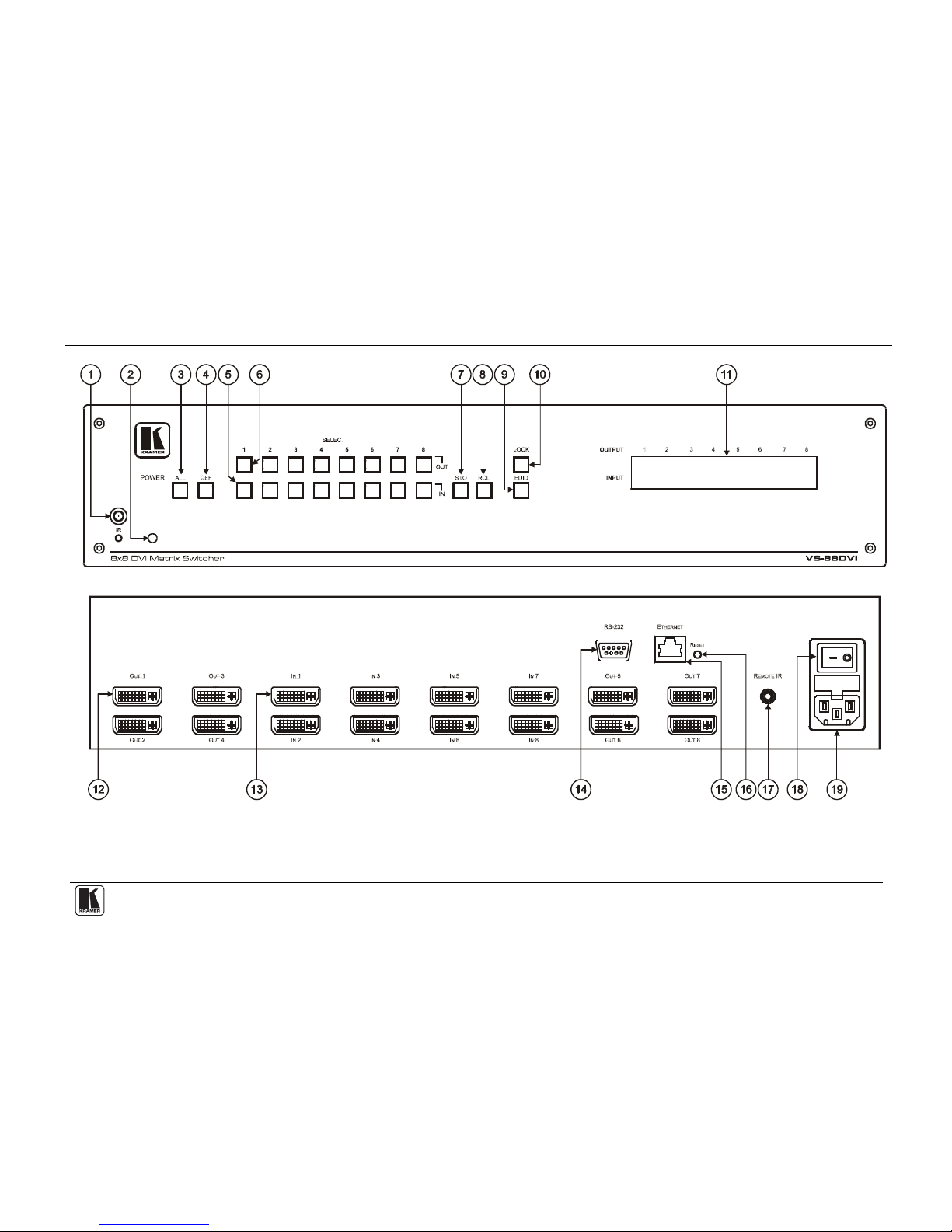
Thank you for purchasing the Kramer VS-88DVI 8x8 DVI Matrix Switcher,
which is ideal for conference room presentations and advertising
applications, as well as for rental and staging.
Each package includes the following items:
•The VS-88DVI 8x8 DVI Matrix Switcher
•Power cord2and null-modem adapter
•Windows®-based Kramer control software3
•Windows®-based Ethernet Configuration Manager and Virtual
Serial Port Manager
•Kramer RC-IR3 Infrared Remote Control Transmitter (including
the required batteries and a separate user manual4)
•This user manual4
2 Getting Started
We recommend that you:
•Unpack the equipment carefully and save the original box and
packaging materials for possible future shipment
•Review the contents of this user manual
•Use Kramer high-performance high resolution cables5
1 GROUP 1: Distribution Amplifiers; GROUP 2: Switchers and Matrix Switchers; GROUP 3: Control Systems;
GROUP 4: Format/Standards Converters; GROUP 5: Range Extenders and Repeaters; GROUP 6: Specialty AV Products;
GROUP 7: Scan Converters and Scalers; GROUP 8: Cables and Connectors; GROUP 9: Room Connectivity;
GROUP 10: Accessories and Rack Adapters; GROUP 11: Sierra Products
2 We recommend that you use only the power cord supplied with this device
3 Downloadable from our Web site at http://www.kramerelectronics.com
4 Download up-to-date Kramer user manuals from our Web site at http://www.kramerelectronics.com
5 The complete list of Kramer cables is on our Web site at http://www.kramerelectronics.com

KRAMER: SIMPLE CREATIVE TECHNOLOGY
Getting Started
2
2.1 Quick Start
This quick start chart summarizes the basic setup and operation steps.

Overview
3
3 Overview
The VS-88DVI is an 8x8 DVI Matrix Switcher that accepts up to eight DVI
inputs and routes the selected DVI1input signal to any or all of eight DVI
outputs.
The VS-88DVI features:
•An OFF button to disconnect an output
•A PANEL LOCK button to prevent unwanted tampering with the
buttons on the front panel
•I-EDIDPro™ Kramer Intelligent EDID Processing™, an intelligent
EDID handling and processing algorithm that ensures Plug and
Play operation for DVI systems.
•16 preset memory locations for quick access to common
configurations
•2U height to fit into a standard 19” professional rack enclosure
Control the VS-88DVI using the front panel buttons, or remotely via:
•RS-232 serial commands transmitted by a touch screen system, PC,
or other serial controller
•The Kramer infrared remote control transmitter
•The ETHERNET
•An external remote IR receiver (optional), see Section 4.1
3.1 Defining the EDID
The Extended Display Identification Data (EDID2) is a data-structure,
provided by a display, to describe its capabilities to a graphics card (that is
connected to the display’s source). The EDID enables the graphic source to
“know” what kind of monitor is connected to the output. The EDID
includes the manufacturer’s name, the product type, the timing data
supported by the display, the display size, luminance data and (for digital
displays only) the pixel mapping data.
1 DVI-D (Digital). Note that only the digital signal (DVI-D) is available on the DVI connector
2 Defined by a standard published by the Video Electronics Standards Association (VESA)

KRAMER: SIMPLE CREATIVE TECHNOLOGY
Your VS-88DVI
4
3.2 Recommendations for Best Performance
To achieve the best performance:
•Use only high-quality connection cables1to avoid interference,
deterioration in signal quality due to poor matching, and elevated
noise levels (often associated with low quality cables).
•Avoid interference from neighboring electrical appliances that may
adversely influence signal quality and position your Kramer VS-
88DVI away from moisture, excessive sunlight, and dust
4 Your VS-88DVI
Figure 1, Table 1, and Table 2 define the unit.
1 Available from Kramer Electronics on our Web site at http://www.kramerelectronics.com

Your VS-88DVI
5
Figure 1: VS-88DVI 8x8 DVI Matrix Switcher Front and Rear Views

KRAMER: SIMPLE CREATIVE TECHNOLOGY
Your VS-88DVI
6
Table 1: VS-88DVI 8x8 DVI Matrix Switcher Front Panel Features
# Feature Function
1 IR Receiver LED The yellow LED is illuminated when receiving signals from the infrared
remote control transmitter
2 POWER LED Illuminates green when receiving power
3 ALL Button Use ALL to select all outputs (see Section 7.1)
4 OFF Button Use OFF to disconnect one or all outputs (see Section 7.2)
5 SELECT IN Press an INPUT selector button to select an input (from 1 to 8)
6 OUT Press an OUTPUT selector button to select an output (from 1 to 8)
7 STO Button Press to store the present setup
8 RCL Button Press to recall a saved setup
9 EDID Button1Press to acquire the EDID (see Section 7.4)
10 LOCK Button Press to toggle disengaging the front panel buttons and to acquire the EDID
11 7-segment Display Displays the status of the inputs switched to the outputs (marked above
each input)
Table 2: VS-88DVI 8x8 DVI Matrix Switcher Rear Panel Features
# Feature Function
12 IN DVI Connectors Connect to the DVI sources (from 1 to 8)
13 OUT DVI Connectors Connect to the DVI acceptors (from 1 to 8)
14 RS-232 9-pin D-sub Port Connects to the PC or the RS-232 Remote Controller
15 ETHERNET Connector Connects to the PC or other Ethernet Controller
16 RESET Button Press the reset button to reset to the ETHERNET factory default
definitions2:
IP number −192.168.1.39
Mask – 255.255.255.0
Gateway – 192.168.1.1
17 REMOTE IR Opening3Connects to an external IR receiver unit for controlling the machine via an
IR remote controller instead of using the front panel IR receiver4
18 Power Switch Switch for turning the unit ON or OFF
19 Power Connector with Fuse AC connector enabling power supply to the unit
1 Illuminates when configuring the EDID
2 First disconnect the power cord and then connect it again while pressing the RESET button. The unit powers up and loads
its memory with the factory default definitions
3 Covered by a cap. The 3.5mm connector at the end of the internal IR connection cable fits through this opening
4 Optional. Can be used instead of the front panel (built-in) IR receiver to remotely control the machine (only if the internal
IR connection cable has been installed)

Your VS-88DVI
7
4.1 Using the IR Transmitter
You can use the RC-IR3 IR transmitter to control the machine via the built-in IR
receiver on the front panel or, instead, via an optional external IR receiver1. The
external IR receiver can be located up to 15 meters away from the machine. This
distance can be extended to up to 60 meters when used with three extension
cables2.
Before using the external IR receiver, be sure to arrange for your Kramer
dealer to insert the internal IR connection cable3with the 3.5mm connector
that fits into the REMOTE IR opening on the rear panel. Connect the
external IR receiver to the REMOTE IR 3.5mm connector.
1 Model: C-A35M/IRR-50
2 Model: C-A35M/A35F-50
3 P/N: 505-70434010-S

KRAMER: SIMPLE CREATIVE TECHNOLOGY
Installing the VS-88DVI in a Rack
8
5 Installing the VS-88DVI in a Rack
This section provides instructions for rack mounting the unit.

Connecting the VS-88DVI 8x8 DVI Matrix Switcher
9
6 Connecting the VS-88DVI 8x8 DVI Matrix Switcher
To connect the VS-88DVI, as the example in Figure 2 illustrates, do the
following1:
1. Connect up to eight DVI sources2(for example, computer graphics sources)
to the IN DVI connectors.
2. Connect the OUT DVI connectors to up to eight DVI acceptors2(for
example, DVI displays).
3. If required, connect a PC and/or controller to the RS-232 port (see Section
7.5) and/or the ETHERNET port (see Section 7.6).
4. Connect the power cord (not shown in Figure 2).
5. If required, acquire the EDID (see Section 7.4).
Figure 2: Connecting the VS-88DVI 8x8 DVI Matrix Switcher
1 Switch OFF the power on each device before connecting it to your VS-88DVI. After connecting your VS-88DVI, switch on
its power and then switch on the power on each device
2 You do not have to connect all the inputs and the outputs

KRAMER: SIMPLE CREATIVE TECHNOLOGY
Operating the VS-88DVI 8x8 DVI Matrix Switcher
10
7 Operating the VS-88DVI 8x8 DVI Matrix Switcher
This section describes how to:
•Route inputs to outputs (see Section 7.1)
•Disconnecting outputs (see Section 7.2)
•Store and recall a setup (see Section 7.3)
•Acquire the EDID (see Section 7.4)
•Control the machine via RS-232 (see Section 7.5)
•Control the machine via the ETHERNET port (see Section 7.6)
7.1 Routing Inputs to Outputs
To route an input to an output:
•Press an OUT key, followed by an IN key to route this input to that
output
To route one input to all outputs:
•Press ALL followed by an IN button. The input is routed to all
outputs
7.2 Disconnecting the Outputs
To disconnect one output:
•Press the OUT button of the output to disconnect and press OFF
To disconnect all outputs at once:
•Press the ALL button and then press OFF. This disconnects all the
outputs
7.3 Storing and Recalling a Setup
You can use the STO and RCL buttons to store up to 16 setups1and then
recall them, as Figure 3 illustrates:
Figure 3: SELECTOR Buttons1
1 IN 1 is used for setup # 1 and OUT 1 is used for setup # 9

Operating the VS-88DVI 8x8 DVI Matrix Switcher
11
To store a setup:
1. Set the machine to the desired input/output connection setup.
2. Press the STO button.
The STO button flashes.
3. Select an OUT or IN SELECT button to store the machine setup (for
example, OUT 5).
4. Press the LOCK button2to store the current setup.
In this example, the OUT 5 button stores the setup.
To recall a setup:
1. Press the RCL button.
The RCL button flashes.
2. Press the relevant OUT or IN button that stored the setup.
In this example, press OUT 5.
3. Press the LOCK button to recall the stored setup.
7.4 Acquiring the EDID
You can acquire the EDID from:
•A single connected output (see Section 7.4.1)
•Several sets of inputs and outputs (see Section 7.4.2)
•The default EDID (see Section 7.4.3)
7.4.1 Acquiring an EDID from a Single Connected Output
To acquire or change the EDID of a new output display:
1. Turn ON the VS-88DVI.
2. Connect the required acceptor to the output from which you want to acquire
the EDID.
3. Press the EDID and STO buttons simultaneously and hold them for 3
seconds.
Both buttons flash.
4. Press the IN SELECTOR button to which the EDID is copied.
The selected input number flashes on the display.
5. Select the OUT SELECTOR button from which the EDID is acquired.
6. Press the EDID button.
The process is complete when the display returns to normal.
1 The gray numbers (1 to 16) in Figure 3 that illustrate the corresponding store/recall configuration numbers, are for the
purpose of illustration only and do not actually appear on the buttons
2 You have to press the LOCK button within 10 seconds, before the store operation times out

KRAMER: SIMPLE CREATIVE TECHNOLOGY
Operating the VS-88DVI 8x8 DVI Matrix Switcher
12
7.4.2 Acquiring an EDID from Several Sets of Inputs and Outputs
To acquire the EDID from several sets of inputs and outputs (for example,
OUT 1 to IN 1 and OUT 6 to IN 3), do the following:
1. Enter the EDID mode:
Turn ON the VS-88DVI
Connect the required acceptors to the outputs from which you
want to acquire the EDID
Press the EDID and STO buttons simultaneously and hold them
for 3 seconds.
Both buttons flash
2. Set the first input output pair (for example, OUT 1 to IN 1)
Press the SELECT IN 1 button to which the first EDID is
copied
The selected input number 1 flashes on the display
Press the SELECT OUT 1 button from which the EDID is
acquired
Press the SELECT IN 1 button again.
The IN 1 button ceases to flash
3. Set the second input output pair (for example, OUT 6 to IN 3)
Press the SELECT IN 3 button to which the next EDID is
copied
The selected input number 3 flashes on the display.
Press the SELECT OUT 6 button from which the second EDID
is acquired
Press the SELECT IN 3 button again.
The IN 3 button ceases to flash
4. Press the SELECT IN 1 and IN 3 buttons to which you want to copy the
EDID.
5. Make sure that the relevant input numbers flash on the display.
6. Press the EDID button.
The process is complete when the display returns to normal.

Operating the VS-88DVI 8x8 DVI Matrix Switcher
13
7.4.3 Acquiring the Default EDID
To reset to the default EDID, do the following:
1. Turn ON the VS-88DVI.
2. Press the EDID and STO buttons simultaneously and hold them for 3
seconds.
Both buttons flash.
3. Press the SELECT IN button to which the EDID is copied.
The selected input number flashes on the display.
4. Press the OFF button until a "0" (zero) appears on the display.
5. Press the EDID button.
The process is complete when the display returns to normal.
7.5 Controlling via RS-232 (for example, using a PC)
To connect a PC to the VS-88DVI unit, using the null-modem adapter
provided with the machine (recommended):
•Connect the RS-232 9-pin D-sub rear panel port on the VS-88DVI
unit to the null-modem adapter and connect the null-modem
adapter with a 9-wire flat cable to the RS-232 9-pin D-sub port on
your PC
To connect a PC to the VS-88DVI unit, without using a null-modem adapter:
•Connect the RS-232 9-pin D-sub port on your PC to the RS-232
9-pin D-sub rear panel port on the Master VS-88DVI unit, as
Figure 4 illustrates
Figure 4: Connecting a PC without using a Null-modem Adapter
9-pin D-sub
(From PC) 9-pin D-sub
(Male)
If a shielded cable is used, connect the shield to PIN 5
PIN 4 is connected to PIN 6
PINs 8, 7, 1 are connected together
PIN 5 Connected to PIN 5 (Ground)
PIN 3 Connected to PIN 2
PIN 2 Connected to PIN 3

KRAMER: SIMPLE CREATIVE TECHNOLOGY
Operating the VS-88DVI 8x8 DVI Matrix Switcher
14
7.6 Controlling via ETHERNET
You can connect the VS-88DVI via the Ethernet, using a crossover cable
(see Section 7.6.1) for direct connection to the PC or a straight-through
cable (see Section 7.6.2) for connection via a network hub or network
router1.
7.6.1 Connecting the ETHERNET Port directly to a PC (Crossover
Cable)
You can connect the Ethernet port of the VS-88DVI to the Ethernet port on
your PC, via a crossover cable with RJ-45 connectors.
This type of connection is recommended for identifying the VS-88DVI
with the factory configured default IP address
After connecting the Ethernet port, configure your PC as follows:
1. Right-click the My Network Places icon on your desktop.
2. Select Properties.
3. Right-click Local Area Connection Properties.
4. Select Properties.
The Local Area Connection Properties window appears.
5. Select the Internet Protocol (TCP/IP) and click the Properties Button (see
Figure 5).
1 After connecting the Ethernet port, you have to install and configure your Ethernet Port. For detailed instructions, see the
“Ethernet Configuration (FC-11) guide.pdf” file in the technical support section on our Web site:
http://www.kramerelectronics.com

Operating the VS-88DVI 8x8 DVI Matrix Switcher
15
Figure 5: Local Area Connection Properties Window
6. Select Use the following IP Address, and fill in the details as shown in
Figure 6.
7. Click OK.
Figure 6: Internet Protocol (TCP/IP) Properties Window
7.6.2 Connecting the ETHERNET Port via a Network Hub (Straight-
Through Cable)
You can connect the Ethernet port of the VS-88DVI to the Ethernet port on
a network hub or network router, via a straight through cable with RJ-45
connectors.

KRAMER: SIMPLE CREATIVE TECHNOLOGY
Technical Specifications
16
7.6.3 Control Configuration via the Ethernet Port
To control several units via the Ethernet, connect the Master unit
(Machine # 1) via the Ethernet port to the LAN port of your PC. Use your
PC initially to configure the settings (see Section 7.6).
8 Technical Specifications
The VS-88DVI technical specifications are shown in Table 3:
Table 3: VS-88DVI Technical Specifications1
INPUTS: 8 DVI, 1.2Vpp on DVI Molex 24-pin female connectors; DDC signal 5Vpp (TTL)
OUTPUTS: 8 DVI, 1.2Vpp on DVI Molex 24-pin female connectors; DDC signal 5Vpp (TTL)
BANDWIDTH: Supports up to 1.65Gbps bandwidth per graphic channel
COMPLIANCE WITH
STANDARDS: Supports DVI 1.1
MAX RESOLUTION: Up to UXGA; 1080p, 1920x1200
POWER SOURCE: 100−240VAC; 50/60Hz, 43VA
CONTROLS: Front panel buttons, Infrared remote control transmitter, RS-232, Ethernet
DIMENSIONS: 19" x 7" x 2U W, D, H
WEIGHT: 2.5kg (5.5lbs) approx.
ACCESSORIES: Power cord, infrared remote controller, null-modem adapter
OPTIONS: Kramer cables2
9 Hex Table
Table 4 lists the Hex values for a single machine (MACHINE # 1):
Table 4: VS-88DVI Hex Codes for Switching via RS-232
Switching Video Channels OUT 8OUT 7OUT 6OUT 5OUT 4OUT 3OUT 2OUT 1 01 81 88 8101 81 87 8101 81 86 8101 81 85 8101 81 84 8101 81 83 8101 81 82 8101 81 81 81
IN 1 01 82 88 8101 82 87 8101 82 86 8101 82 85 8101 82 84 8101 82 83 8101 82 82 8101 82 81 81
IN 2 01 83 88 8101 83 87 8101 83 86 8101 83 85 8101 83 84 8101 83 83 8101 83 82 8101 83 81 81
IN 3 01 84 88 8101 84 87 8101 84 86 8101 84 85 8101 84 848101 84 83 8101 84 82 8101 84 81 81
IN 4 01 85 88 8101 85 87 8101 85 86 8101 85 85 8101 85 84 8101 85 83 8101 85 82 8101 85 81 81
IN 5 01 86 84 8101 86 83 8101 86 82 8101 86 81 8101 86 84 8101 86 83 8101 86 82 8101 86 81 81
IN 6 01 87 88 8101 87 87 8101 87 86 8101 87 85 8101 87 84 8101 87 83 8101 87 82 8101 87 81 81
IN 7 01 88 88 8101 88 87 8101 88 86 8101 88 85 8101 88 84 8101 88 83 8101 88 82 8101 88 81 81
IN 8
1 Specifications are subject to change without notice
2 For best results, use Kramer cables such as the C-HDMI-DVI series

Kramer Protocol 2000
17
10 Kramer Protocol 2000
The VS-88DVI is compatible with Kramer’s Protocol 20001(version 0.50)
(below)2. This RS-232/RS-485 communication protocol uses four bytes of
information as defined below. For RS-232, a null-modem connection
between the machine and controller is used. The default data rate is 9600
baud, with no parity, 8 data bits and 1 stop bit.
Table 5: Protocol Definitions
MSB LSB
DESTI-
NATION INSTRUCTION
0 D N5 N4 N3 N2 N1 N0
7 6 5 4 3 2 1 0
1st byte
INPUT
1 I6 I5 I4 I3 I2 I1 I0
7 6 5 4 3 2 1 0
2nd byte
OUTPUT
1 O6 O5 O4 O3 O2 O1 O0
7 6 5 4 3 2 1 0
3rd byte
MACHINE NUMBER
1 OVR X M4 M3 M2 M1 M0
7 6 5 4 3 2 1 0
4th byte
1st BYTE: Bit 7 – Defined as 0.
D – “DESTINATION”: 0 - for sending information to the switchers (from the PC);
1 - for sending to the PC (from the switcher).
N5…N0 – “INSTRUCTION”
The function that is to be performed by the switcher(s) is defined by the INSTRUCTION (6 bits). Similarly, if a function is
performed via the machine’s keyboard, then these bits are set with the INSTRUCTION NO., which was performed. The
instruction codes are defined according to the table below (INSTRUCTION NO. is the value to be set for N5…N0).
2nd BYTE: Bit 7 – Defined as 1.
I6…I0 – “INPUT”.
When switching (ie. instruction codes 1 and 2), the INPUT (7 bits) is set as the input number which is to be switched.
Similarly, if switching is done via the machine’s front-panel, then these bits are set with the INPUT NUMBER which was
switched. For other operations, these bits are defined according to the table.
3rd BYTE: Bit 7 – Defined as 1.
O6…O0 – “OUTPUT”.
When switching (ie. instruction codes 1 and 2), the OUTPUT (7 bits) is set as the output number which is to be switched.
Similarly, if switching is done via the machine’s front-panel, then these bits are set with the OUTPUT NUMBER which was
switched. For other operations, these bits are defined according to the table.
4th BYTE: Bit 7 – Defined as 1.
Bit 5 – Don’t care.
OVR – Machine number override.
M4…M0 – MACHINE NUMBER.
1 The instruction codes in Table 6 are a sub-set of the Protocol 2000. You can find the full protocol on our Web site at
http://www.kramerelectronics.com
2 You can download our user-friendly “Software for Calculating Hex Codes for Protocol 2000” from the technical support
section on our Web site at: http://www.kramerelectronics.com
Other manuals for VS-88DVI
1
Table of contents
Other Kramer Matrix Switcher manuals

Kramer
Kramer Cobra MX-1616 User manual

Kramer
Kramer MTX3-34-M User manual

Kramer
Kramer AFM-20DSP-AEC User manual

Kramer
Kramer VS-88HDCPxl User manual

Kramer
Kramer XL 1616VS User manual

Kramer
Kramer VS-88HD User manual

Kramer
Kramer MTX3-16-M User manual

Kramer
Kramer VS-44DT User manual

Kramer
Kramer 20-04400030 User manual

Kramer
Kramer VS-88UHD User manual

Kramer
Kramer XL 3216VS User manual

Kramer
Kramer 1616HDEE User manual

Kramer
Kramer 3232DS User manual

Kramer
Kramer VP-729 User manual

Kramer
Kramer VS-84HDCPxl User manual

Kramer
Kramer VP-436 User manual

Kramer
Kramer VS-4228 User manual

Kramer
Kramer XL 1208V2 User manual

Kramer
Kramer 1616DS User manual

Kramer
Kramer 88DS User manual