Bedienungsanleitung Membranventil DV-5625-U / -SS
Manual diaphragm valve DV-5625 Series
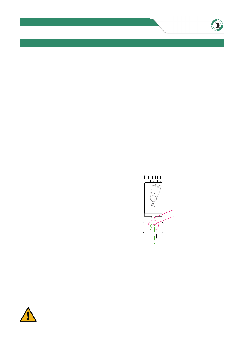
Note:
Do not turn the fitting too deeply into the valve.
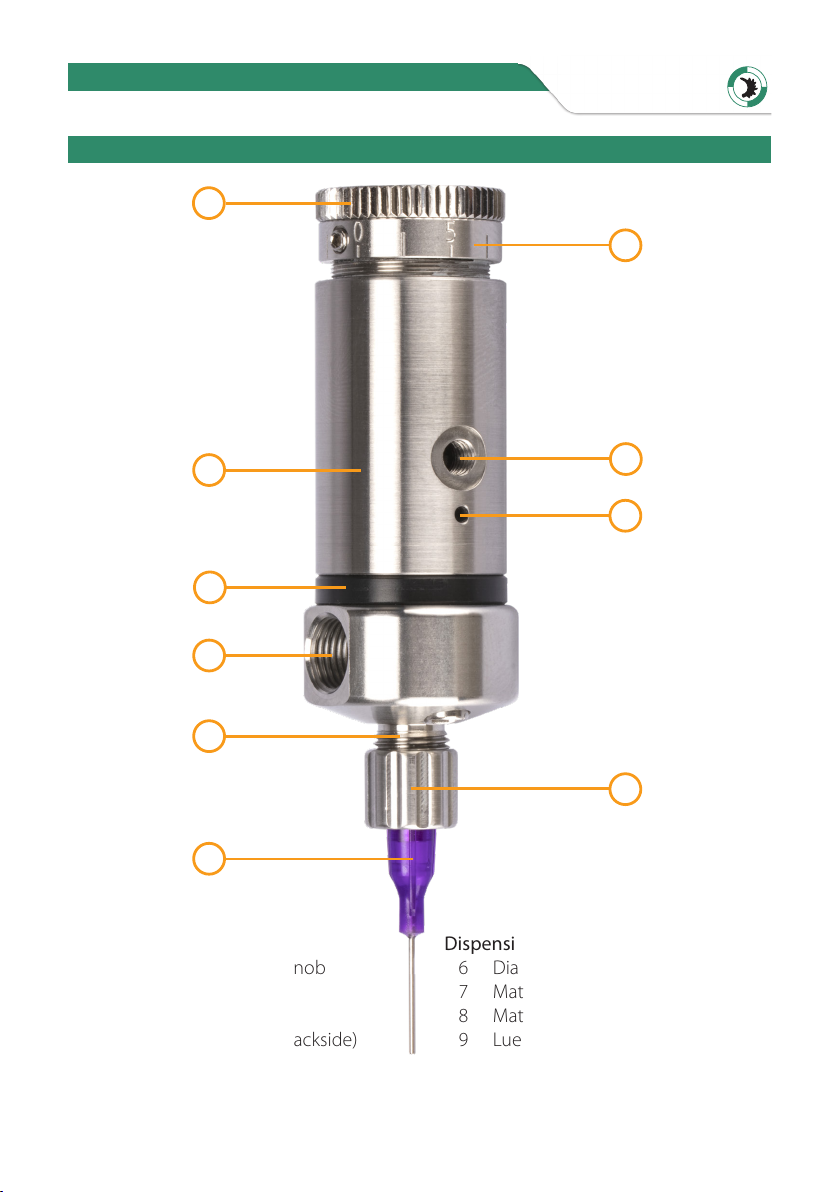
4. Place a suitable dispensing tip on the material outlet and fix it with the union nut.
5. Set the material pressure as follows (but max. 5.0 bar). Set the material pressure to
max. 0.5 bar if you want to dispense very thin material (such as water or solvents).
Set the material pressure for highly viscous material to approx. 2.0 bar and adjust it
according to the required dispensing.
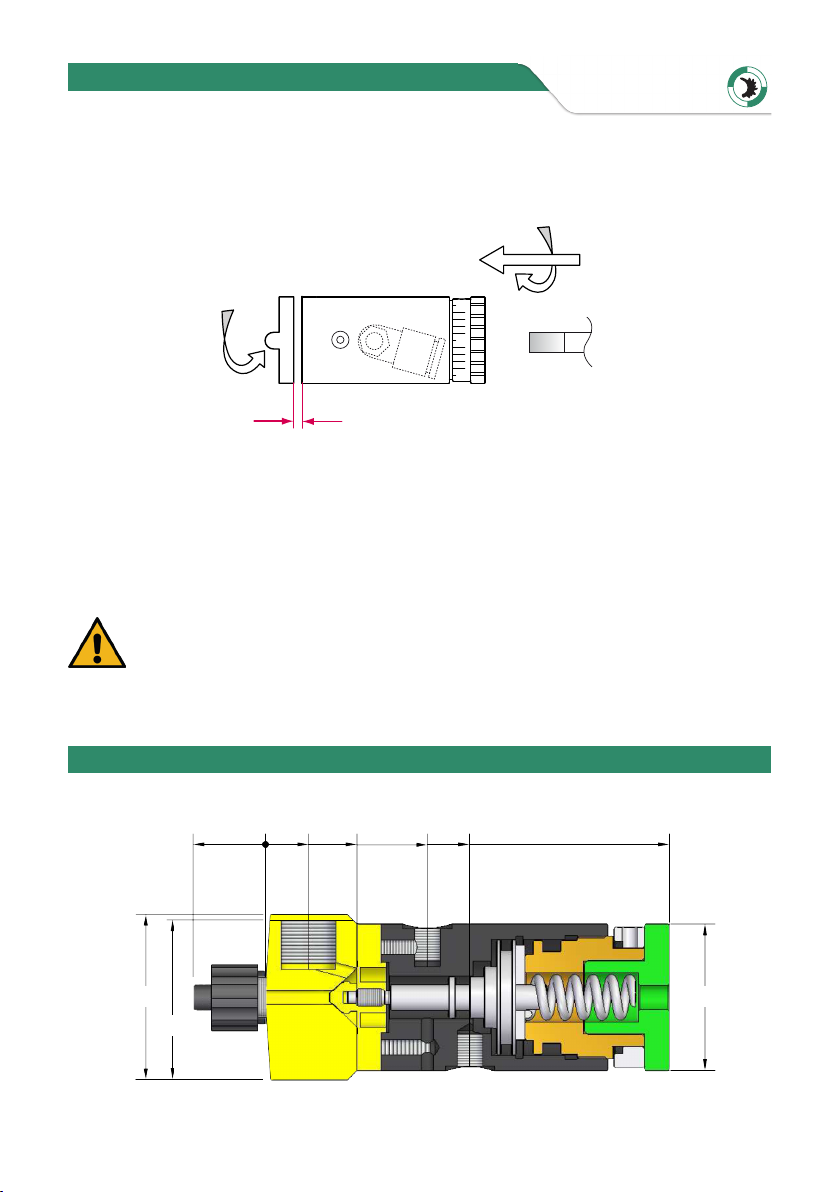
6. On delivery, the adjusting screw is set to position 3 (center of full stroke).
Increase or decrease the setting as required. The maximum stroke is 0.6 mm.
This corresponds to a complete turn of the set screw.
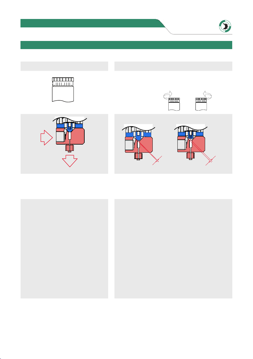
Note:
If you turn the adjusting screw 2 turns or more often counterclockwise, the
return spring loses its effect and the valve opens continuously. This causes
the material to be dispensed continuously, even if no control pressure is
applied.
7. Adjust the valve, material pressure, and controller settings so that material slowly
exits the valve.
(This prevents bubbles from forming in the dispensing material during dispensing.)
8. Select the operating mode„Timer“ or„Manual“ on the controller depending on the
desired dispensing.
9. You can influence the dispensing result using the following 4 options:
Increase or decrease material
pressure
Pressure increase leads to increase
of dispensing quantity
Pressure reduction leads to a reduction
of the dispensing quantity
Diameter of dosing tip Thin dispensing tip reduces the dispensing quantity
Thick dispensing tip increases the dispensing quantity
Adjusting screw for
stroke adjustment
Large stroke setting increases the dispensing quantity
Low stroke setting reduces the dispensing quantity
Dispensing time
Long dosing time increases the dispensing quantity
Short dosing time reduces the dispensing quantity
8