KROHNE Display and adjustment module for OPTISOUND... User manual

Operating Instructions
Display and adjustment module for
OPTISOUND sensors
Document
ID: 30603

2
Contents
Display and adjustment module for OPTISOUND sensors •
30603-EN-150102
Contents
1 About this document
1.1 Function ........................................................................................................................... 3
1.2 Target group ..................................................................................................................... 3
1.3 Symbols used................................................................................................................... 3
2 For your safety
2.1 Authorised personnel ....................................................................................................... 4
2.2 Appropriate use................................................................................................................ 4
2.3 Warning about incorrect use............................................................................................. 4
2.4 General safety instructions............................................................................................... 4
2.5 CE conformity................................................................................................................... 4
2.6 NAMUR recommendations .............................................................................................. 4
2.7 Safety instructions for Ex areas ........................................................................................ 5
3 Product description
3.1 Conguration.................................................................................................................... 6
3.2 Principle of operation........................................................................................................ 6
3.3 Operation ......................................................................................................................... 6
3.4 Packaging, transport and storage..................................................................................... 6
4 Mounting
4.1 Installation procedure....................................................................................................... 8
5 Setup
5.1 Adjustment system........................................................................................................... 9
5.2 General functions ............................................................................................................. 9
5.3 Functions - 4 … 20 mA/HART ........................................................................................ 15
5.4 Menu plan ultrasonic sensor .......................................................................................... 17
6 Maintenanceandfaultrectication
6.1 Maintenance .................................................................................................................. 20
6.2 Instrument repair ............................................................................................................ 20
7 Dismount
7.1 Dismounting steps.......................................................................................................... 21
7.2 Disposal ......................................................................................................................... 21
8 Supplement
8.1 Technical data ................................................................................................................ 22
8.2 Dimensions .................................................................................................................... 22
Safety instructions for Ex areas
TakenoteoftheExspecicsafetyinstructionsforExapplications.
These instructions are attached as documents to each instrument
with Ex approval and are part of the operating instructions manual.
Editing status: 2014-11-24
3
1 About this document
Display and adjustment module for OPTISOUND sensors •
30603-EN-150102
1 About this document
1.1 Function
This operating instructions manual has all the information you need
for quick setup and safe operation of the display and adjustment
module. Please read this manual before you start setup.
1.2 Target group
This operating instructions manual is directed to trained specialist
personnel. The contents of this manual should be made available to
these personnel and put into practice by them.
1.3 Symbols used
Information, tip, note
This symbol indicates helpful additional information.
Caution: If this warning is ignored, faults or malfunctions can result.
Warning: If this warning is ignored, injury to persons and/or serious
damage to the instrument can result.
Danger: If this warning is ignored, serious injury to persons and/or
destruction of the instrument can result.
Ex applications
This symbol indicates special instructions for Ex applications.
SIL applications
This symbol indicates instructions for functional safety which must be
taken into account particularly for safety-relevant applications.
• List
The dot set in front indicates a list with no implied sequence.
→ Action
This arrow indicates a single action.
1 Sequence of actions
Numbers set in front indicate successive steps in a procedure.

4
2 For your safety
Display and adjustment module for OPTISOUND sensors •
30603-EN-150102
2 For your safety
2.1 Authorised personnel
All operations described in this operating instructions manual must
be carried out only by trained specialist personnel authorised by the
plant operator.
During work on and with the device the required personal protective
equipment must always be worn.
2.2 Appropriate use
The display and adjustment module is a pluggable unit for OPTI-
SOUND level sensors.
2.3 Warning about incorrect use
Inappropriate or incorrect use of the instrument can give rise to
application-specichazards,e.g.vesseloverllordamagetosystem
components through incorrect mounting or adjustment.
2.4 General safety instructions
This is a state-of-the-art instrument complying with all prevailing
regulations and guidelines.The instrument must only be operated in a
technicallyawlessandreliablecondition.Theoperatorisresponsible
for the trouble-free operation of the instrument.
During the entire duration of use, the user is obliged to determine the
compliance of the necessary occupational safety measures with the
current valid rules and regulations and also take note of new regula-
tions.
The safety instructions in this operating instructions manual, the na-
tional installation standards as well as the valid safety regulations and
accident prevention rules must be observed by the user.
For safety and warranty reasons, any invasive work on the device
beyond that described in the operating instructions manual may be
carried out only by personnel authorised by the manufacturer. Arbi-
traryconversionsormodicationsareexplicitlyforbidden.
The safety approval markings and safety tips on the device must also
be observed.
2.5 CE conformity
ThedevicefulllsthelegalrequirementsoftheapplicableECguide-
lines.ByaxingtheCEmarking,weconrmsuccessfultestingofthe
product.
2.6 NAMUR recommendations
NAMUR is the automation technology user association in the process
industry in Germany. The published NAMUR recommendations are
acceptedasthestandardineldinstrumentation.

5
2 For your safety
Display and adjustment module for OPTISOUND sensors •
30603-EN-150102
ThedevicefulllstherequirementsofthefollowingNAMURrecom-
mendations:
• NE 21 – Electromagnetic compatibility of equipment
For further information see www.namur.de.
2.7 Safety instructions for Ex areas
PleasenotetheEx-specicsafetyinformationforinstallationandop-
eration in Ex areas. These safety instructions are part of the operating
instructions manual and come with the Ex-approved instruments.

6
3 Product description
Display and adjustment module for OPTISOUND sensors •
30603-EN-150102
3 Product description
3.1 Conguration
The scope of delivery encompasses:
• Display and adjustment module
• Documentation
– this operating instructions manual
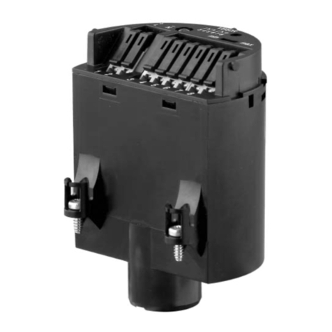
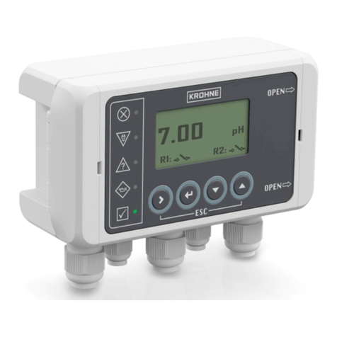
The indicating/adjustment module consists of a display with full dot
matrix as well as four keys for adjustment.
An LED background lighting is integrated in the display and can be
switched on via the adjustment menu.
3.2 Principle of operation
The display and adjustment module is used for measured value
indication, adjustment, and diagnostics for the following OPTISOUND
sensors:
• OPTISOUND 3010 C
• OPTISOUND 3020 C
• OPTISOUND 3030 C
• OPTISOUND 3040 C
• OPTISOUND 3050 C
The display and adjustment module is integrated into the respective
sensor housing. After installation, sensor as well as module without
housing cover are splash-proof.
Power is supplied directly by the respective sensor. An additional con-
nection is not necessary.
3.3 Operation
The adjustment is carried out via the integrated keys. The entered
parameters are generally saved in the respective sensor. A copy func-
tion enables loading of the parameters into the display and adjust-
ment module.
3.4 Packaging, transport and storage
Your instrument was protected by packaging during transport. Its
capacity to handle normal loads during transport is assured by a test
based on ISO 4180.
The packaging of standard instruments consists of environment-
friendly, recyclable cardboard. For special versions, PE foam or PE
foil is also used. Dispose of the packaging material via specialised
recycling companies.
Transport must be carried out in due consideration of the notes on the
transport packaging. Nonobservance of these instructions can cause
damage to the device.
Scope of delivery
Equipment
Area of application
Voltage supply
Packaging
Transport

7
3 Product description
Display and adjustment module for OPTISOUND sensors •
30603-EN-150102
The delivery must be checked for completeness and possible transit
damage immediately at receipt. Ascertained transit damage or con-
cealed defects must be appropriately dealt with.
Up to the time of installation, the packages must be left closed and
stored according to the orientation and storage markings on the
outside.
Unless otherwise indicated, the packages must be stored only under
the following conditions:
• Not in the open
• Dry and dust free
• Not exposed to corrosive media
• Protected against solar radiation
• Avoiding mechanical shock and vibration
• Storage and transport temperature see chapter "Supplement -
Technical data - Ambient conditions"
• Relative humidity 20 … 85 %
Transport inspection
Storage
Storage and transport
temperature

8
4 Mounting
Display and adjustment module for OPTISOUND sensors •
30603-EN-150102
4 Mounting
4.1 Installation procedure
The display and adjustment module can be inserted or removed at
any time. It is not necessary to interrupt the voltage supply.
Proceed as follows for mounting the display and adjustment module:
1. Unscrew the housing cover
2. Place the display and adjustment module in the desired position
ontheelectronics(youcanchooseanyoneoffourdierentposi-
tions - each displaced by 90°)
Fig. 1: Insert display and adjustment module
3. Press the display/adjustment module lightly onto the electronics
and turn it to the right until it snaps in
4. Screw housing cover with inspection window tightly back on
Note:
Ifyouintendtoretrottheinstrumentwithadisplayandadjustment
module for continuous measured value indication, a higher cover with
an inspection glass is required.
Dismounting is carried out in reverse order.
Mount/Dismount display
and adjustment module

9
5 Setup
Display and adjustment module for OPTISOUND sensors •
30603-EN-150102
5 Setup
5.1 Adjustment system
1
2
Fig. 2: Display and adjustment elements
1 LC display
2 Indication of the menu item number
3 Adjustment keys
• [OK] key:
– Move to the menu overview
– Conrmselectedmenu
– Edit parameter
– Save value
• [->] key to select:
– Menu change
– Select list entry
– Select editing position
• [+] key:
– Change value of the parameter
• [ESC] key:
– Interrupt input
– Jump to next higher menu
The sensor is adjusted via the four keys of the display and adjust-
ment module.The LC display indicates the individual menu items. The
functions of the individual keys are shown in the above illustration.
Approx. 10 minutes after the last pressing of a key, an automatic reset
tomeasuredvalueindicationistriggered.Anyvaluesnotconrmed
with [OK] will not be saved.
5.2 General functions
OPTISOUND ultrasonic sensors have manifold functions at their
disposal. This allows them to be adapted perfectly to the respective
Key functions
Adjustment system
Introduction

10
5 Setup
Display and adjustment module for OPTISOUND sensors •
30603-EN-150102
application. These functions are structured in menu form. Some of the
functionsaresensor-specic.Thesearedescribedintheoperatingin-
structions manual of the respective sensor. Other functions, however,
have general character, i.e. they are available in sensors that operate
according to other measuring principles.
The general functions are described in this paragraph. The functions
of the display/adjustment module are determined by the sensor and
correspond to the respective software version of the sensor.
Information:
Therespectivemenuitemnumberdiersdependingonthesensor
type and signal output.
The following presentations are available in the measured value
display:
• Level as digital value, sensor TAG
• Level as digital value and bar graph, sensor TAG
With [->]youselectdierentpresentationsofthemeasuredvalue.
From each of these presentations, you can reach with [OK] the menu
overview. With [ESC] you move from the menu overview again to the
measured value indication.
In the menu overview you select the appropriate menu with [->] and
open it with [OK]. Then the individual menu items are available.
▶Basic adjustment
Display
Diagnostics
Service
Info
Menu section, basic adjustment
Todampprocess-dependentmeasuredvalueuctuations,setan
integration time of 0 … 999 s in this menu item.
Depending on the sensor type, the factory setting is 0 s or 1 s.
Damping
0 s
Inthismenuitemyouselectthelinearizationcurve:
• Linear
• Horizontalcylindricaltank
• Spherical tank
• User programmable
Userprogrammablemeans:Switchingonalinearizationcurvepro-
grammed via PC and PACTware
Thelinearizationcurvecreatesacorrelationbetweenheightand
volume. It takes into account the vessel geometry for the displayed
measured value and current output.
Measured value indica-
tion
Menu overview
Damping
Linearisation curve

11
5 Setup
Display and adjustment module for OPTISOUND sensors •
30603-EN-150102
The default setting is linear.
Linearisation curve
Linear
In the menu item "Sensor-TAG" you edit a 12-digit measurement loop
name. An unambiguous designation can hence be assigned to the
sensor, e.g. the measurement loop name or the tank or product des-
ignation. In digital systems and in the documentation of larger plants,
asingulardesignationshouldbeenteredforexactidenticationof
individual measuring sites.
The available digits comprise:
• Letters from A … Z
• Numbers from 0 … 9
• Special characters +, -, /, -
Factory setting is "Sensor".
Sensor-TAG
Sensor
Menu section, diagnostics
The respective min. and max. measured values are saved in the sen-
sor. The values are displayed in the menu item "Peak values".
• Min. and max. distance in m(d)
• Min. and max. temperature
Peak value indicator
When non-contact level sensors are used, the measurement can be
inuencedbytherespectiveprocessconditions.Inthismenuitem,
the measurement reliability of the level echo is displayed as dB value.
The measurement reliability equals signal strength minus noise. The
higher the value, the more reliable the measurement.With a function-
ing measurement, the values are > 10 dB.
The instrument status is displayed in this menu item. If no failure is
detected by the sensor, "OK" will be displayed. If a failure is detected,
therewillbeasensor-specicashingfaultsignal,forexample
"E013". The failure is also displayed in clear text, for example "No
measured value available".
Information:
The fault message as well as the clear text indication are also carried
out in the measured value display.
Edit sensor TAG
Peak value indicator
Meas. reliability
Sensor status

12
5 Setup
Display and adjustment module for OPTISOUND sensors •
30603-EN-150102
Meas. reliability
Sensor status
Thesignalcurvesenablearstroughevaluationofthemeasurement.
The following curves are available:
• Echo curve
• False echo curve
• Trend curve
The echo curve displays the echoes as signal strength in dB in rela-
tion to distance.
The false echo curve displays the saved false echoes (see menu
"Service") of the empty vessel as signal strength in "dB" over the
measuring range.
Curve selection
A comparison of the echo curve and the false echo curve allows a
more detailled evaluation of measurement reliability.The selected
curve is updated continuously. With the [OK] key, a submenu with
zoomfunctionsisopened.
The following functions are available with "Echo and false echo
curve":
• "X-Zoom": Zoom function for the meas. distance
• "Y-Zoom":1,2,5and10xsignalmagnicationin"dB"
• "Unzoom":Resetthepresentationtothenominalmeasuringrange
withoutmagnication
In the menu item "Trend curve" the following are available:
• "X-Zoom": Resolution
– 1 minute
– 1 hour
– 1 day
• "Stop/Start": Interrupt a recording or start a new recording
• "Unzoom":Resettheresolutiontominutes
As default setting, the recording pattern has 1 minute. With the adjust-
ment software PACTware, this pattern can be also set to 1 hour or 1
day.
Echo curve
Curve selection
Curve presentation

13
5 Setup
Display and adjustment module for OPTISOUND sensors •
30603-EN-150102
Menu section, service
In this menu item you simulate individual level values via the current
output. This allows the signal path to be tested, e.g. via connected
indicating instruments or the input card of the processing system.
The following simulation variables are available:
• Percent
• Current
• Distance
How to start the simulation:
1. Push [OK]
2. Select the requested simulation variable with [->]andconrm
with [OK].
3. Set the requested numerical value with [+] and [->].
4. Push [OK]
The simulation is activated and a corresponding current in the range
of 4 … 20 mA is outputted.
How to interrupt the simulation:
→ Push [ESC]
Information:
The simulation is automatically terminated 10 minutes after the last
pressing of a key.
Simulation
Start simulation?
Withtheresetfunction,modiedvaluesarereset.Threesubfunctions
are available:
• Basic adjustment
– Resetthevaluesmodiedwiththedisplayandadjustment
moduletothesensor-specicbasicsetting(seechart)
• Default setting
– Likebasicsetting,butalsoresetsspecialparametersmodied
with PACTware to delivery status
• Peak values measured value and temperature
– Reset the min./max. values of level and temperature to the cur-
rent values
Reset values, basic setting
Menu Menu item Ultrasonic
Basic adjustment Unit of measurement Deleted
Min. adjustment Upperdeadzone,dependingoninstrument
Max. adjustment end nominal measuring range
Linearisation curve Linear
Simulation of measured
values
Reset

14
5 Setup
Display and adjustment module for OPTISOUND sensors •
30603-EN-150102
Menu Menu item Ultrasonic
Sensor-TAG Sensor
Display Displayed value 1 Distance
Scaling 0 % = 0.0, 100 % = 100.0
Service Current output Output mode: 4-20 mA
Failure mode: < 3.6 mA ▼
Min. current: 3.8 mA
Reset
Select reset?
In this menu item you select the internal unit of calculation of the sen-
sor: m(d) or ft(d).
Unit of measurement
m(d)
The sensor is already set to the ordered national language. In this
menu item you can change the language. The following languages
are available:
• Deutsch
• English
• Français
• Espanõl
• Pycckuu
Language
German
With this function
• data are read from the sensor
• Data written into the sensor.
The data are permanently saved in an EEPROM memory in the
display/adjustment module and remain there even in case of voltage
failure. From there, they can be written into one or several sensors
and kept as a backup for a possible sensor exchange. When data is
written into the sensor, the instrument type from which the data origi-
nate as well as the TAG no. of that sensor are displayed.
Copy sensor data
Unit of measurement
Language
Copy sensor data

15
5 Setup
Display and adjustment module for OPTISOUND sensors •
30603-EN-150102
Menu section, info
In this menu item, the PIN is activated/deactivated permanently.
Enteringa4-digitPINprotectsthesensordataagainstunauthorized
accessandunintentionalmodications.IfthePINisactivatedperma-
nently, it can be deactivated temporarily (i.e. for approx. 60 min.) in
any menu item.The instrument is delivered with the PIN set to 0000.
PIN
Disable permanently?
Only the following functions are permitted with activated PIN:
• Select menu items and show data
• Read data from the sensor into the display and adjustment mod-
ule.
In this menu item the most important sensor information can be
displayed:
• Instrument type, e.g. OPTISOUND 3010 C
• Serial number: 8-digit number, e.g. 12345678
• Date of manufacture: Date of the factory calibration
• Software version: Edition of the sensor software
• Date of last change using PC: Date of the last change of sensor
parameters via PC
• Sensordetails,e.g.approval,processtting,seal,measuring
range, electronics, housing, cable entry, plug, cable length etc.
Instrument type
Serial number
Cal. date
Software revision
Last change using PC
Sensor characteristics
5.3 Functions - 4 … 20 mA/HART
The4…20mA/HARTspecialfunctionsarebrieydescribedinthis
paragraph.The respective range of functions of the display and ad-
PIN
Info
Introduction

16
5 Setup
Display and adjustment module for OPTISOUND sensors •
30603-EN-150102
justment module is determined by the sensor and the sensor software
version.
In the menu item "Display"youcandenehowthemeasuredvalue
should be presented on the display.
The following indication values are available:
• Height
• Distance
• Current
• Scaled
• Percent
• Lin. percent
The selection "scaled" opens the menu items "Display unit" and
"Scaling". In "Display unit" there are the following options:
• Height
• Ground
• Flow
• Volume
• Without unit
Dependingonselection,thedierentunitsareinturnavailable.
In the menu item "Scaling", the requested numerical value with deci-
mal point is entered for 0 % and 100 % of the measured value.
There is the following relationship between the indication value in the
menu "Display" and the adjustment unit in the menu "Device settings":
• With ultrasonics, the indication value "Distance" means: Presenta-
tion of the measured value in the selected adjustment unit, e.g.
m(d).
Displayed value
Scaled
Display unit
Volume
l
Scaling
0 % = 0.0 l
100 % = 100.0 l
In the menu item "Current output" you determine the behaviour of the
current output during operation and in case of failure.The following
options are available:
Display
Current output

17
5 Setup
Display and adjustment module for OPTISOUND sensors •
30603-EN-150102
Current output
Characteristics 4 … 20 mA
20 … 4 mA
Failure mode1) Hold value
20.5 mA
22.0 mA
< 3.6 mA
Min. current2) 3.8 mA
4 mA
The values in bold font represent the data of the factory setting.
In HART multidrop mode, the current is constantly 4 mA.This value
does not change even in case of failure.
Current output
Output mode: 4-20 mA
Failure mode: 22 mA
Min. current: 3.8 mA
HARToersstandardandmultidropmode.
Themodestandardwiththexedaddress0meansoutputofthe
measured value as 4 … 20 mA signal.
In Multidrop mode, up to 15 sensors can be operated on one two-wire
cable. An address between 1 and 15 must be assigned to each sen-
sor.3)
In this menu item you determine the HART mode and enter the ad-
dress for multidrop.
HART mode
Standard
Address 0
The default setting is standard with address 0.
5.4 Menu plan ultrasonic sensor
Information:
Depending on the version and application, the highlighted menu
windows may not always be available.
HART mode
1) Value of the current output in case of failure, e.g. if no valid measured value is
delivered.
2) This value is not underrun during operation.
3) The4…20mAsignaloftheHARTsensorisswitchedo.Thesensor
consumes a constant current of 4 mA. The measuring signal is transmitted
exclusively as digital HART signal.

18
5 Setup
Display and adjustment module for OPTISOUND sensors •
30603-EN-150102
Basic adjustment
▶Basic adjustment 1
Display
Diagnostics
Service
Info
Min. adjustment 1.1
0.00 %
=
4.000 m(d)
3.000 m(d)
Max. adjustment 1.2
100.00 %
=
1.000 m(d)
2.000 m(d)
Medium 1.3
Liquid
Vessel form 1.4
Storage tank
Damping 1.5
0 s
Linearisation curve 1.6
Linear
Sensor-TAG 1.7
Sensor
Display
Basic adjustment 2
▶Display
Diagnostics
Service
Info
Displayed value 2.1
Scaled
Display unit 2.2
Volume
m³
Scaling 2.3
0 % = 0.0 m³
100 % = 100 m³
Diagnostics
Basic adjustment 3
Display
▶Diagnostics
Service
Info
Peak value indicator 3.1
Distance min.: 0.234 m(d)
Distance max.: 5.385 m(d)
Meas. reliability 3.2
15 dB
Sensor status
OK
Curve selection 3.3
Echo curve ▼
Echo curve 3.4
Presentation of the echo
curve

19
5 Setup
Display and adjustment module for OPTISOUND sensors •
30603-EN-150102
Service
Basic adjustment 4
Display
Diagnostics
▶Service
Info
False signal suppression 4.1
Change now?
Extended setting 4.2
None ▼
Current output 4.3
Characteristic: 4-20 mA ▼
Fail. mode: < 3.6 mA ▼
Min. current: 3.8 mA ▼
Simulation 4.4
Start simulation?
Reset 4.5
Select reset?
Unit of measurement 4.6
m(d) ▼
select?
Language 4.7
Deutsch ▼
HART mode 4.8
Standard
Address 0
Copy sensor data 4.9
Copy sensor data?
PIN 4.10
Enable?
Info
Basic adjustment 5
Display
Diagnostics
Service
▶Info
Instrument type 5.1
Serial number
12345678
Date of manufacture 5.2
21. January 2009
Software version
3.50
Last change using PC 5.3
21. January 2009
Sensor characteristics 5.4
Display now?

20
6Maintenanceandfaultrectication
Display and adjustment module for OPTISOUND sensors •
30603-EN-150102
6 Maintenanceandfaultrectication
6.1 Maintenance
If the instrument is used properly, no special maintenance is required
in normal operation.
6.2 Instrument repair
If a repair is necessary, please proceed as follows:
On our homepage in the Internet under
http://www.krohne-mar.com/leadmin/
media-lounge/PDF-Download/Specimen_e.pdf
you can download a return form.
By doing this you help us carry out the repair quickly and without hav-
ing to call back for needed information.
• Printandlloutoneformperinstrument
• Clean the instrument and pack it damage-proof
• Attach the completed form and possibly also a safety data sheet to
the instrument
Table of contents
Other KROHNE Control Unit manuals

KROHNE
KROHNE SHD 200 User manual

KROHNE
KROHNE SMARTMAC 200 W Wiring diagram

KROHNE
KROHNE SHD 200 User manual

KROHNE
KROHNE OPTISWITCH 5100 C User manual

KROHNE
KROHNE SHD 200 Wiring diagram

KROHNE
KROHNE ESK4 Series Wiring diagram

KROHNE
KROHNE SMARTMAC 400 Wiring diagram

KROHNE
KROHNE SHD 200 User manual

KROHNE
KROHNE SMARTMAC 400 User manual

KROHNE
KROHNE OPTISWITCH 3100 C User manual
Popular Control Unit manuals by other brands

Mec
Mec Excelerator ME990S-2DFM Installation and operating manual

Texas Instruments
Texas Instruments INA190EVM user guide

Jung
Jung TK SV STG 60 REG Product information

Sensata
Sensata LineGard PGFM Series quick start guide

Keysight Technologies
Keysight Technologies 34946A user guide

Hirschmann
Hirschmann PTN-4-DSL-LW user manual