KROHNE H250 M40 ESK4-Basic User manual

Signal converter for variable-area flowmeters
Description of PROFIBUS interface
Description of PROFIBUS interfaceDescription of PROFIBUS interface
Description of PROFIBUS interface
The documentation is only complete when used in combination with the relevant
documentation of the flowmeter.
H250 M40 ESK4
H250 M40 ESK4H250 M40 ESK4
H250 M40 ESK4 Supplementary instructions
Supplementary instructionsSupplementary instructions
Supplementary instructions
© KROHNE 03/2014 - 4002251801 - AD H250/M40 PROFIBUS R01 en
AD_H250_M40_PB_PA_R01_en_4002251801_PRT.book Page 1 Friday, March 21, 2014 1:14 PM

CONTENTS
2 www.krohne.com 03/2014 - 4002251801 - AD H250/M40 PROFIBUS R01 en
H250 M40 ESK4
1 Safety instructions 3
1.1 Installation........................................................................................................................ 3
1.2 Scope of the document..................................................................................................... 3
1.3 Scope of delivery............................................................................................................... 3
2 PROFIBUS PA 4
2.1 Software history ............................................................................................................... 4
2.2 Device overview ................................................................................................................ 4
2.3 PROFIBUS PA Profile implementation ............................................................................ 5
2.4 Technical data................................................................................................................... 6
3 Electrical connection 8
3.1 Topology of a PROFIBUS PA network .............................................................................. 8
3.2 Electrical connection for signal converter....................................................................... 9
4 Commissioning / Operation 10
4.1 Hardware settings ..........................................................................................................10
4.2 GSD files ......................................................................................................................... 11
4.3 Ident. Number selector .................................................................................................. 12
4.4 Summary ........................................................................................................................ 16
4.5 Configuration of cyclic data transfer.............................................................................. 16
4.6 Cyclic data....................................................................................................................... 17
4.6.1 Input data .............................................................................................................................. 17
4.6.2 Output data............................................................................................................................ 22
4.7 Diagnosis ........................................................................................................................ 23
AD_H250_M40_PB_PA_R01_en_4002251801_PRT.book Page 2 Friday, March 21, 2014 1:14 PM

SAFETY INSTRUCTIONS 1
3
H250 M40 ESK4
www.krohne.com03/2014 - 4002251801 - AD H250/M40 PROFIBUS R01 en
Safety instructions
1.1 Installation
If the ESK4 Device Description is not already installed on the PDM System a so called Device
Install ESK4 PROFIBUS-PA PDM is needed (available as download from KROHNE ‘Download
Center’on the internet or on CD-ROM from KROHNE). For installing the DD with the Device
Install refer to the “PDM Manual”section:”Integrating Devices”. Please read also the
“readme.txt”, which is also contained in the Device Install.
1.2 Scope of the document
These instructions are supplementary to the standard product documentation of the signal
converter. The details described herein, in particular the safety information, are valid and shall
be adhered to. The present supplementary instructions provide additional information for the
device when it is connected to a PROFIBUS network.
1.3 Scope of delivery
A device for PROFIBUS communication is supplied with:
Supplementary instructions for the PROFIBUS PA interface (this document)
INFORMATION!
The information in this document only contains the data applicable to the PROFIBUS module.
The technical data in the signal converter Handbook is valid in its current version, provided that it
is not rendered invalid or replaced by these supplementary instructions.
AD_H250_M40_PB_PA_R01_en_4002251801_PRT.book Page 3 Friday, March 21, 2014 1:14 PM

2PROFIBUS PA
4
H250 M40 ESK4
www.krohne.com 03/2014 - 4002251801 - AD H250/M40 PROFIBUS R01 en
PROFIBUS PA
2.1 Software history
2.2 Device overview
The ESK4-PA transmitter has a modular design. It consists of the following components:
•ESK4-Basic module
•ESK4-PA module
The ESK4-Basic module performs the measuring while the ESK4-PA module provides
communication technology and power supply for both modules.
Depending on the factory calibration and the assembled sensor the ESK4-PA transmitter can be
used to perform flow or level measurement.
The ESK4-PA transmitter has a MBP interface (Manchester coded, bus powered) to connect the
device to a PROFIBUS PA network. The software supports the PROFIBUS PA Profile 3.02. Both,
cyclic services towards a control system (e.g. PLC) as well as acyclic services for operating with
engineering tools (e.g. DD/DTM based tools) are supported.
The PROFIBUS station address can be set via a hardware switch or via PROFIBUS services.
Issued Signal converter Application program System integration
Mth./
year
Hardware Firmware Hardware Software Driver Version Model name
07/12 PROFIBUS
PA module
Ident. No.
4000769602
V2.1.x / 120717 Simatic
PCS7
or
other SPS
of other
manufact.
HW Config
or
other
Software of
other SPS
manufact.
GSD (device
specific) KR014531.GSD ESK4-PA
GSD (profile
specific) PA139740.GSD Flow 1 AI 1 TOT
(Phy MBP)
Laptop / PC PDM
(≥6.0 SP5) DD
(Ident.-No.)
Pactware DTM ≥
AD_H250_M40_PB_PA_R01_en_4002251801_PRT.book Page 4 Friday, March 21, 2014 1:14 PM

PROFIBUS PA 2
5
H250 M40 ESK4
www.krohne.com03/2014 - 4002251801 - AD H250/M40 PROFIBUS R01 en
2.3 PROFIBUS PA Profile implementation
The PROFIBUS PA Profile 3.02 defines standardized parameters and functions for PROFIBUS
devices used for process control. It describes a PROFIBUS device as a function block application,
i.e. parameters and functions are grouped into different blocks. In the ESK4-PA transmitter the
following blocks are implemented:
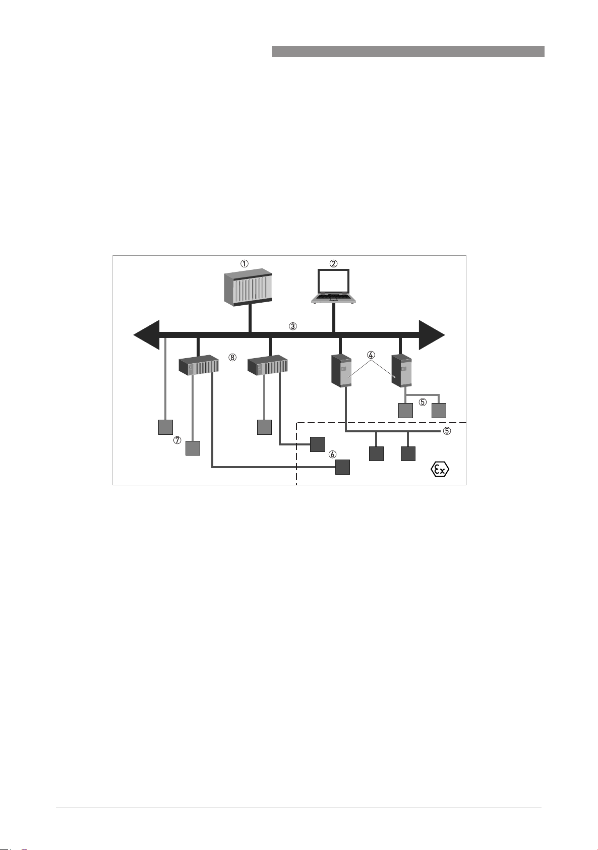
The Analog Input Function Block and the Totalizer Function Blocks provide the data interface
towards a process control system (e.g. a PLC); i.e. their input/output data can be read/written by
the control system. In a PROFIBUS network this is done via cyclic communication services.
From the PROFIBUS point of view the ESK4-PA transmitter is designed as a modular device with
three slots. While the Analog Input Function Block is assigned (as virtual module) to slot 1 the
Totalizer Function Blocks are assigned (as virtual modules) to slot 2 and 3. This assignment is
fixed and cannot be modified by the user. Nevertheless the measuring data for each Function
Block is selectable according to the following tables:
Device calibrated for Volume Flow
The calibration units are used as default units.
Block Usage
1 Physical Block (PB) contains identification and diagnosis parameters of the device
1 Flow Transducer Block
(TB-Flow) contains parameters and functions to control the flow measurement
1 Level Transducer Block
(TB-Level) contains parameters and functions to control the level measurement
1 Analog Input Function Block
(AI-FB) contains parameters and functions to control the measuring output;
provides the measuring value(s)
2 Totalizer Function Blocks
(Tot-FB) contains parameters and functions to control/provide the counter
value(s)
Slot
SlotSlot
Slot Module type
Module typeModule type
Module type Measuring data
Measuring dataMeasuring data
Measuring data 1
1AI-FB Volume flowrate (Default setting)
Mass flowrate
Board temperature
2Totalizer-FB Totalized volume flowrate (Default setting)
Totalized mass flowrate
3Totalizer-FB Totalized volume flowrate
Totalized mass flowrate (Default setting)
1Selection of measuring data can be changed by modifying the channel parameter via acyclic PROFIBUS services.
AD_H250_M40_PB_PA_R01_en_4002251801_PRT.book Page 5 Friday, March 21, 2014 1:14 PM

2PROFIBUS PA
6
H250 M40 ESK4
www.krohne.com 03/2014 - 4002251801 - AD H250/M40 PROFIBUS R01 en
Device calibrated for Mass Flow
The calibration units are used as default units.
Device calibrated for Level
The default unit for level is [%]. Calibration unit is used as default unit for board temperature.
2.4 Technical data
Slot
SlotSlot
Slot Module type
Module typeModule type
Module type Measuring data
Measuring dataMeasuring data
Measuring data 1
1AI-FB Volume flowrate
Mass flowrate (Default setting)
Board temperature
2Totalizer-FB Totalized volume flowrate
Totalized mass flowrate (Default setting)
3Totalizer-FB Totalized volume flowrate (Default setting)
Totalized mass flowrate
1Selection of measuring data can be changed by modifying the channel parameter via acyclic PROFIBUS services.
Slot
SlotSlot
Slot Module type
Module typeModule type
Module type Measuring data
Measuring dataMeasuring data
Measuring data 1
1AI-FB Level (Default setting)
Board temperature
2Totalizer-FB 2 Totalized volume flowrate (Default setting)
Totalized mass flowrate
3Totalizer-FB 2 Totalized volume flowrate
Totalized mass flowrate (Default setting)
1Selection of measuring data can be changed by modifying the channel parameter via acyclic PROFIBUS services.
2Totalizing is not active if the device is calibrated for level measurement.
Hardware
Type PROFIBUS MBP interface according to IEC 61158-2 with 31.25 kbit/s;
voltage mode (MBP = Manchester Coded Bus Powered)
Polarity Independent of polarity at electrical connection
Base current 16 mA
FDE Separate fault disconnection electronics provided
(FDE = Fault Disconnection Electronics)
Max. error current 23 mA
Start current after 10ms Lower than base current
Electrical connections
Device power supply Bus powered 9...32 VDC - not intrinsically safe
Bus powered 9...24 VDC - intrinsically safe
Basic current 16 mA
Maximum error current 23 mA
Start current after 10 ms lower than basic current
Polarity sensitivity No
Minimum cycle time 250 ms
AD_H250_M40_PB_PA_R01_en_4002251801_PRT.book Page 6 Friday, March 21, 2014 1:14 PM

PROFIBUS PA 2
7
H250 M40 ESK4
www.krohne.com03/2014 - 4002251801 - AD H250/M40 PROFIBUS R01 en
Software
Supported GSD KR014531.GSD
PA139740.GSD
PA139700.GSD
KROHF201.GSD
YP01F201.GSD
Device profile PROFIBUS PA Profile V3.02; conformance class B, compact
Address setting Default: 126
Hardware switch: 0…126/selection via PROFIBUS service
Set_Slave_Add.
PROFIBUS service Set_Slave_Add: 0...125
Factory_Reset=2712: 126
Write protection Password and/or hardware switch
SAP´s 2× MS1 SAPs –acyclic interface to PLC
3× MS2 SAPs –the number of MS2 Service Access Points is typically equal to
the maximum number of master class 2 tools
Function blocks 1 Physical Block
1 Flow Transducer Block (Variable area)
1 Level Transducer Block
1 Analog Input Function Block
2 Totalizer Function Blocks
AD_H250_M40_PB_PA_R01_en_4002251801_PRT.book Page 7 Friday, March 21, 2014 1:14 PM

3ELECTRICAL CONNECTION
8
H250 M40 ESK4
www.krohne.com 03/2014 - 4002251801 - AD H250/M40 PROFIBUS R01 en
Electrical connection
3.1 Topology of a PROFIBUS PA network
The following diagram shows a typical network configuration with PROFIBUS PA devices in
hazardous and non-hazardous areas, as well as the connection of conventional non-PROFIBUS
devices (e.g. with 4 …20 mA signals) to a PROFIBUS network.
The PROFIBUS PA segment is connected to a segment coupler which, among other things,
provides the conversion to the PROFIBUS DP bus line. In addition it provides the power supply for
bus–powered PROFIBUS PA devices. Refer to the instruction manual of the segment coupler
concerning the DP bus parameters, e.g. the supported baud rates.
Refer also to the PROFIBUS PA User and Installation Guideline (Version 2.2, February 2003 PNO
Order No. 2.092).
Figure 3-1: PROFIBUS PA network
1 Control system (PLC); class 1 master
2 Engineering or operation control tool; class 2 master
3 PROFIBUS DP network with max. 12 Mbit/s
4 PROFIBUS PA segment coupler DP / PA
5 PROFIBUS PA network with 31.25 kbit/s
6 HART®device
7 More devices with 4…20 mA
8 Analogue I/O module
AD_H250_M40_PB_PA_R01_en_4002251801_PRT.book Page 8 Friday, March 21, 2014 1:14 PM

ELECTRICAL CONNECTION 3
9
H250 M40 ESK4
www.krohne.com03/2014 - 4002251801 - AD H250/M40 PROFIBUS R01 en
3.2 Electrical connection for signal converter
Bus cable - Shielding and grounding
The statements of the FISCO model only apply if the used bus cable meets the required
specifications.
In order to ensure optimum electromagnetic compatibility of systems it is important that the
system components, and in particular the bus cables, are shielded. These shields must have as
few gaps as possible.
Polarity reversal has no effect on the function. The cable shield should be connected with
minimum length to the functional ground FE.
ESK4-PA
•2-wire bus powered
•Protected against reverse polarity
•Foundation Fieldbus
•Bus supply voltage 9...32 VDC
•Nominal current 16mA
DANGER!
The signal converter must be properly grounded to avoid personnel shock hazard. All directions,
operating data and connection diagrams do not apply to devices used in hazardous areas; in such
cases, read the special Ex instructions without fail!
AD_H250_M40_PB_PA_R01_en_4002251801_PRT.book Page 9 Friday, March 21, 2014 1:14 PM

4COMMISSIONING / OPERATION
10
H250 M40 ESK4
www.krohne.com 03/2014 - 4002251801 - AD H250/M40 PROFIBUS R01 en
Commissioning / Operation
4.1 Hardware settings
A hardware switch is available at the ESK4-PA module to set the PROFIBUS station address as
well as to activate a hardware write protection. It is realized by a switch with 8 separate
switches.
The actual station address is calculated by adding the corresponding values shown in the
diagram above. Each value depends on the setting of its corresponding switch. Default setting
for each switch is “off”; i.e. write protection is disabled and station address set to an invalid value
(127).
According to the PROFIBUS PA Profile 3.02 the following rules are considered in conjunction
with the hardware switch:
1 Power supply D / D-
2 Hardware switch
3 Connection to basic module
Function Value (off) Value (on) Label
Write protection disabled enabled WP
Station address + 64 + 0 64
+ 32 + 0 32
+ 16 + 0 16
+ 8 + 0 8
+ 4 + 0 4
+ 2 + 0 2
+ 1 + 0 1
AD_H250_M40_PB_PA_R01_en_4002251801_PRT.book Page 10 Friday, March 21, 2014 1:14 PM

COMMISSIONING / OPERATION 4
11
H250 M40 ESK4
www.krohne.com03/2014 - 4002251801 - AD H250/M40 PROFIBUS R01 en
Hardware write protection:
•If hardware write protection is enabled acyclic write access via PROFIBUS is refused to all
parameters. Only index parameters remain writeable which are required to specify an entry
within a table which shall be read. In addition the FI_Index remains writeable to read I&M
data via the Call service.
•Hardware write protection is ignored if a password is entered to enable write access to
service and/or production parameters. This will provide a comfortable write access to
parameters without modifying user settings.
•Controlling the totalizers via cyclic services (i.e. via data exchange) remains possible even if
hardware write protection is enabled. The corresponding parameters might be modified via
these services.
•Changing the station address via Set_Slave_Add service remains available even if hardware
write protection is enabled.
•Automatic Ident. Number adaptation via Set_Slave_Add service or SetPrm service remains
available even if hardware write protection is enabled.
•Selection of classic/condensed status via Set_Prm service remains available even if
hardware write protection is enabled. The corresponding parameter(s) might be modified via
this service.
Station address
•If the hardware switch provides a valid station address (<=125) this address is used by the
device. The Set_Slave_Add service is ignored. Automatic Ident. Number adaptation is not
possible via Set_Slave_Add service in this case. Physical block parameter FACTORY_RESET
code 2712 (reset station address to its default value) is rejected.
•If the hardware switch provides an invalid address (>125) the switch is ignored by the device.
The Set_Slave_Add service is accepted. Physical block parameter FACTORY_RESET code
2712 (reset station address to its default value) is accepted even if No_add_Cfg flag is set.
•If the hardware switch is shifted from an invalid address to a valid address the device takes
over the selected hardware address. The flag No_Add_Chg will be set. Its former setting is
ignored.
•If the hardware switch is shifted from a valid address to an invalid address the device takes
over the default address 126. The flag No_Add_Chg will be cleared.
•The station address can be modified via the hardware switch even if the device is write
protected (via hardware write protection and/or password protection).
4.2 GSD files
The GSD file contains information that will be needed for configuration of the PROFIBUS DP
communication network. Supplementary files (e.g. ___.bmp and ___.dib) contain icons which will
represent the PROFIBUS devices in the view of the bus configuration system/master system. The
files must be loaded into the configuration program before. Follow the instructions in the
manual of the host supplier when installing GSD file and supplementary files.
The GSD files of all KROHNE devices with PROFIBUS PA interface are available at the KROHNE
internet site for download.
INFORMATION!
If it is supported by the host configuration tool the device entry for the ESK4-PA transmitter will
be located within the slave family
“
PROFIBUS PA
”
.
AD_H250_M40_PB_PA_R01_en_4002251801_PRT.book Page 11 Friday, March 21, 2014 1:14 PM

4COMMISSIONING / OPERATION
12
H250 M40 ESK4
www.krohne.com 03/2014 - 4002251801 - AD H250/M40 PROFIBUS R01 en
4.3 Ident. Number selector
Within a PROFIBUS network the type of a PROFIBUS slave is identified by its Ident. Number
which is unique for this slave type. The ESK4-PA transmitter supports different Ident. Numbers.
Therefore it can be installed for different use cases. When the Ident. Number is changed the
behaviour of the device concerning the cyclic data transfer is changed; i.e. the maximum number
of transferred measuring values and/or the length and content of the diagnosis information will
be different. The user can select the required Ident. Number by an engineering tool (e.g.
DD/DTM). The Ident. Number is set via the parameter IDENT_NUMBER_SELECTOR.
The following settings are supported by the ESK4-PA transmitter:
•Automatic adaptation mode (factory setting)
•Manufacturer specific Ident. Number (4531hex)
•Profile specific Ident. Number (9740hex)
•Profile specific Ident. Number (9700hex)
•Compatibility mode (ESK3-PA: F201hex)
•Compatibility mode (Profile: 9740hex)
Automatic adaptation mode (factory setting)
Automatic adaptation mode (factory setting)Automatic adaptation mode (factory setting)
Automatic adaptation mode (factory setting)
If the parameter IDENT_NUMBER_SELECTOR is set to this mode the device will select its
operation mode during start-up of the cyclic data transfer according to the used GSD file. The
active Ident. Number is set to one of the settings described below. If the
IDENT_NUMBER_SELECTOR is changed to this mode the current Ident. Number is not changed
until the cyclic data transfer is (re-)started.
INFORMATION!
Depending on the components in the PROFIBUS network the automatic adaptation might fail.
The active Ident. Number has to be selected by the user via an engineering tool in this case. The
parameter IDENT_NUMBER_SELECTOR has to be set to a fixed Ident. Number.
AD_H250_M40_PB_PA_R01_en_4002251801_PRT.book Page 12 Friday, March 21, 2014 1:14 PM

COMMISSIONING / OPERATION 4
13
H250 M40 ESK4
www.krohne.com03/2014 - 4002251801 - AD H250/M40 PROFIBUS R01 en
Manufacturer specific Ident. Number (4531hex)
Manufacturer specific Ident. Number (4531hex)Manufacturer specific Ident. Number (4531hex)
Manufacturer specific Ident. Number (4531hex)
This setting provides complete functionality of the ESK4-PA transmitter. All Functions Blocks (1
AI-FB, 2 Tot-FBs) are available for cyclic data transfer. Device specific diagnosis information is
transferred in addition to the Profile diagnosis.
Cyclic layout:
GSD file KR014531.GSD is required in this mode. This file might be used for all types of
PROFIBUS DP/PA segment couplers.
Profile specific Ident. Number (9740hex)
Profile specific Ident. Number (9740hex)Profile specific Ident. Number (9740hex)
Profile specific Ident. Number (9740hex)
This setting is accepted only if the ESK4-PA transmitter is calibrated for flow measurement.
Functionality is reduced to the requirements which are mandatory in the PA Profile; i.e. 1 AI-FB
and 1 Tot-FB are available for cyclic data transfer only. Device specific diagnosis information is
not available via cyclic PROFIBUS services. Nevertheless this behaviour will improve
interchangeability between devices of different vendors because only functions are available
which are provided by all PROFIBUS PA variable area flowmeters. Exchange is possible without
modifying the configuration of the control system.
Cyclic layout:
GSD file PA139740.GSD is required in this mode. This file is provided by PROFIBUS International
(see www.profibus.com). This file might be used for all types of PROFIBUS DP/PA segment
couplers. Take care that “Condensed Status”is not supported by this file.
Slot Function Block Valid GSD Modules
1AI-FB Empty Module
AI: Out
2Totalizer-FB 1 Empty Module
TOT (Id.F.): Total
TOT (Id.F.): SetTot + Total
TOT (Id.F.): ModeTot + Total
TOT (Id.F.): SetTot+ModeTot+Total
TOT (Id.F.): SetTot
TOT (Id.F.): ModeTot
TOT (Id.F.): SetTot + ModeTot
3Totalizer-FB 1
1Totalizing is stopped if the ESK4-PA transmitter is calibrated for level measurement.
INFORMATION!
If another GSD file is used in the PROFIBUS master system the cyclic data transfer cannot be
established in this setting.
Slot Function Block Valid GSD Modules
1AI-FB EMPTY_MODULE
AI
2Totalizer-FB EMPTY_MODULE
TOTAL
SETTOT_TOTAL
SETTOT_MODETOT_TOTAL
INFORMATION!
If another GSD file is used in the PROFIBUS master system the cyclic data transfer cannot be
established in this setting.
AD_H250_M40_PB_PA_R01_en_4002251801_PRT.book Page 13 Friday, March 21, 2014 1:14 PM

4COMMISSIONING / OPERATION
14
H250 M40 ESK4
www.krohne.com 03/2014 - 4002251801 - AD H250/M40 PROFIBUS R01 en
Profile specific Ident. Number (9700hex)
Profile specific Ident. Number (9700hex)Profile specific Ident. Number (9700hex)
Profile specific Ident. Number (9700hex)
This setting is accepted only if the ESK4-PA transmitter is calibrated for level measurement.
Functionality is reduced to the requirements which are mandatory in the PA Profile; i.e. 1 AI-FB
is available for cyclic data transfer only. Device specific diagnosis information is not available via
cyclic PROFIBUS services. Nevertheless this behaviour will improve interchangeability between
devices of different vendors because only functions are available which are provided by all
PROFIBUS PA level devices. Exchange is possible without modifying the configuration of the
control system.
Cyclic layout:
GSD file PA139700.GSD is required in this mode. This file is provided by PROFIBUS International
(see www.profibus.com). This file might be used for all types of PROFIBUS DP/PA segment
couplers. Take care that “Condensed Status”is not supported by this file.
Compatibility mode (ESK3-PA: F201hex)
Compatibility mode (ESK3-PA: F201hex)Compatibility mode (ESK3-PA: F201hex)
Compatibility mode (ESK3-PA: F201hex)
This setting supports a compatibility mode concerning the cyclic data transfer (cyclic
measurement values and diagnosis) if the ESK4-PA transmitter shall be used for replacement of
an ESK3-PA transmitter. The ESK4-PA transmitter emulates the cyclic behaviour of the ESK3-
PA transmitter. Status and diagnosis are restricted to the capabilities of this transmitter.
Therefore it is usually not necessary to modify the configuration of the control system if it is
configured for operation with an ESK3-PA transmitter.
Cyclic layout:
GSD file KROHF201.GSD is required in this mode. If the ESK4-PA transmitter is connected to a
Pepperl+Fuchs PROFIBUS DP/PA segment coupler SK2 or SK3 the GSD file YP01F201.GSD shall
be used. Take care that “Condensed Status”is not supported in this mode for compatibility
reasons.
Slot Function Block Valid GSD Modules
1AI-FB Analog Input (AI) short
Analog Input (AI) long
INFORMATION!
If another GSD file is used in the PROFIBUS master system the cyclic data transfer cannot be
established in this setting.
Slot Function Block Valid GSD Modules
1AI-FB EMPTY_MODULE
Analog Input (AI)
2Totalizer-FB 1 EMPTY_MODULE
Totalizer (Ext.)
SETTOT_TOTAL (Ext.)
SETTOT_MODETOT_TOTAL (Ext.)
3Totalizer-FB 1
1Totalizing is stopped if the ESK4-PA transmitter is calibrated for level measurement.
INFORMATION!
If another GSD file is used in the PROFIBUS master system the cyclic data transfer cannot be
established in this setting.
AD_H250_M40_PB_PA_R01_en_4002251801_PRT.book Page 14 Friday, March 21, 2014 1:14 PM

COMMISSIONING / OPERATION 4
15
H250 M40 ESK4
www.krohne.com03/2014 - 4002251801 - AD H250/M40 PROFIBUS R01 en
Compatibility mode (Profile: 9740hex)
Compatibility mode (Profile: 9740hex)Compatibility mode (Profile: 9740hex)
Compatibility mode (Profile: 9740hex)
This setting supports a compatibility mode concerning the cyclic data transfer (cyclic measurement values
and diagnosis) if the ESK4-PA transmitter shall be used for replacement of an ESK3-PA transmitter while
the ESK3-PA was operating in Profile specific mode. The ESK4-PA transmitter emulates the cyclic
behaviour of the ESK3-PA transmitter. Status and diagnosis are restricted to the capabilities of this
transmitter. Therefore it is usually not necessary to modify the configuration of the control system if it is
configured for operation with an ESK3-PA transmitter.
Cyclic layout:
GSD file PA139740.GSD is required in this mode. This file is provided by PROFIBUS International
(see www.profibus.com). This file might be used for all types of PROFIBUS DP/PA segment
couplers. Take care that “Condensed Status”is not supported by this file.
INFORMATION!
The IDENT_NUMBER_SELECTOR changes the behaviour of the ESK4-PA transmitter from the
communication point of view. In addition it might be necessary to set additional parameters to
suitable values in order to adapt the measuring behaviour to ESK3-PA.
INFORMATION!
Although the cyclic behaviour of the ESK3-PA is emulated by the ESK4-PA transmitter the
acyclic behaviour is not changed. Therefore a DD/DTM for ESK4-PA has to be used to set
parameters/read measuring values and diagnosis even if the compatibility mode is active.
Extended diagnosis information is still available on this way.
Slot Function Block Valid GSD Modules
1AI-FB EMPTY_MODULE
AI
2Totalizer-FB 1 EMPTY_MODULE
TOTAL
SETTOT_TOTAL
SETTOT_MODETOT_TOTAL
1Totalizing is stopped if the ESK4-PA transmitter is calibrated for level measurement.
INFORMATION!
If another GSD file is used in the PROFIBUS master system the cyclic data transfer cannot be
established in this setting.
INFORMATION!
The IDENT_NUMBER_SELECTOR changes the behaviour of the ESK4-PA transmitter from the
communication point of view. In addition it might be necessary to set additional parameters
suitable values in order to adapt the measuring behaviour to ESK3-PA.
INFORMATION!
Although the cyclic behaviour of the ESK3-PA is emulated by the ESK4-PA transmitter the
acyclic behaviour is not changed. Therefore a DD/DTM for ESK4-PA has to be used to set
parameters/read measuring values and diagnosis even if the compatibility mode is active.
Extended diagnosis information is still available on this way.
INFORMATION!
This operation mode cannot be entered via the Automatic adaptation mode (see above).
AD_H250_M40_PB_PA_R01_en_4002251801_PRT.book Page 15 Friday, March 21, 2014 1:14 PM

4COMMISSIONING / OPERATION
16
H250 M40 ESK4
www.krohne.com 03/2014 - 4002251801 - AD H250/M40 PROFIBUS R01 en
4.4 Summary
The following table shows a summary of the supported combinations:
4.5 Configuration of cyclic data transfer
During network configuration the user has to select which function block input/output data shall
be transferred between the PROFIBUS master and the PROFIBUS slave. The GSD file described
above contains several types of modules for this purpose. During configuration a module has to
be assigned to each slot of the device in order to select which data has to be transferred for the
corresponding function blocks. The cyclic layout (see section Ident. Number selector) shows
which module types are valid for each slot. The order of transmission of the data always remains
the same. If an “Empty Module”is assigned to a slot no data will be sent for the corresponding
function block and all function block data following this empty module will move up one position.
Calibration Ident. Number Selector Ident.
Number
GSD File Status
Flow Automatic adaptation mode 4531 KR014531.GSD classic
condensed
9740 PA139740.GSD 1 classic
F201 KROHF201.GSD
YP01F201.GSD classic
Level Automatic adaptation mode 4531 KR014531.GSD classic
condensed
9700 PA139700.GSD 1 classic
F201 KROHF201.GSD
YP01F201.GSD classic
Flow/Level Manufacturer specific Ident.
Number (4531hex) 4531 KR014531.GSD classic
condensed
Flow Profile specific Ident. Number
(9740hex) 9740 PA139740.GSD 1 classic
Level Profile specific Ident. Number
(9700hex) 9700 PA139700.GSD 1 classic
Flow/Level Compatibility mode (ESK3-PA:
F201hex) F201 KROHF201.GSD
YP01F201.GSD classic
Flow/Level Compatibility mode (Profile:
9740hex) 9740 PA139740.GSD 1 classic
1This file is provided by PROFIBUS International (see www.profibus.com)
AD_H250_M40_PB_PA_R01_en_4002251801_PRT.book Page 16 Friday, March 21, 2014 1:14 PM

COMMISSIONING / OPERATION 4
17
H250 M40 ESK4
www.krohne.com03/2014 - 4002251801 - AD H250/M40 PROFIBUS R01 en
4.6 Cyclic data
In a PROFIBUS network cyclic data is described from the point of view of the master. Therefore
input data is transferred from the slave to the master while output data is transferred from the
master to the slave.
4.6.1 Input data
Input data is transferred from the ESK4-PA transmitter to the master for the measuring value
and the totalizer values. The format is the same for both. If input data transfer is configured 5
bytes are transferred for the corresponding slot:
•4 byte float value (Float Format according to IEEE Standard 754 Short Real Number)
•1 byte status value
Float value
Float valueFloat value
Float value
The following example describes the format of the float value according to IEEE Standard 754
Short Real Number:
Float format
Example (binary): 40 F0 00 00 (hex) = 0100 0000 1111 0000 0000 0000 0000 0000
Formula:
Formula:Formula:
Formula:
value = (-1)VZ * 2(Exponent –127) * (1 + Mantissa)
value = (-1)0* 2(129 –127) * (1 + 2-1 + 2-2 + 2-3)
value = 1 * 4 * (1 + 0.5 + 0.25 + 0.125)
value = 7.5
Byte n Byte n+1
Bit7 Bit6 Bit7 Bit6
VZ 27262524232221202-1 2-2 2-3 2-4 2-5 2-6 2-7
Exponent Mantissa
Byte n+2 Byte n+3
Bit7 Bit7
2-8 2-9 2-10 2-11 2-12 2-13 2-14 2-15 2-16 2-17 2-18 2-19 2-20 2-21 2-22 2-23
Mantissa Mantissa
AD_H250_M40_PB_PA_R01_en_4002251801_PRT.book Page 17 Friday, March 21, 2014 1:14 PM

4COMMISSIONING / OPERATION
18
H250 M40 ESK4
www.krohne.com 03/2014 - 4002251801 - AD H250/M40 PROFIBUS R01 en
Status value
Status valueStatus value
Status value
The ESK4-PA PROFIBUS interface supports the PROFIBUS-PA Profile Version 3.02. In this
Profile the Condensed Status and Diagnosis has replaced by default the Classic Status and
Diagnosis of the PROFIBUS-PA Profile Version 3.0. The Condensed Status and Diagnosis has
been created to make diagnostic events more obvious and to allow predictive and preventive
maintenance. Nevertheless Classic Status and Diagnosis is still available for ESK4-PA
transmitters. It is implemented for backwards compatibility to "older" devices or PLC systems
which do not support Condensed Status and Diagnosis.
The device may be switched between "Condensed Status and Diagnosis" and "Classic Status and
Diagnosis"
•automatically during start-up of the cyclic data transfer by setting the parameter PRM_COND
within the Set_Prm service data.
•using an engineering tool (e.g. DD/DTM) to write the parameter COND_STATUS_DIAG (slot 0,
index 43).
Coding for both parameters is:
•0: Classic Status
•1: Condensed Status (factory setting)
The coding of the status value depends on the active status and diagnosis mode. It is described in
the following tables.
Condensed Status
Condensed StatusCondensed Status
Condensed Status
The Condensed Status codes have been defined to allow easier decoding of the information
provided by the PROFIBUS devices. The coding is shown in the following table:
INFORMATION!
The parameter COND_STATUS_DIAG cannot be modified directly if cyclic data transfer is active.
Nevertheless it is reset to the factory setting if a reset to default data is requested by an
engineering tool.
Quality Quality substatus Limits
Gr Gr QS QS QS QS Qu Qu
2726252423222120
0 0 = bad
0 1 = uncertain
1 0 = good (Non Cascade)
1 1 = good (Cascade) - not supported
AD_H250_M40_PB_PA_R01_en_4002251801_PRT.book Page 18 Friday, March 21, 2014 1:14 PM

COMMISSIONING / OPERATION 4
19
H250 M40 ESK4
www.krohne.com03/2014 - 4002251801 - AD H250/M40 PROFIBUS R01 en
Status = bad
Status = uncertain
Status = good (Non Cascade)
Status = Limits
Quality Quality substatus Limits
Gr Gr QS QS QS QS Qu Qu
2726252423222120
00000000= non-specific (not provided by the device)
00100011= passivated (diagnostic alerts inhibited)
001001xx= maintenance alarm, more diagnosis available
001010xx= process related, no maintenance
001111xx= function check / local override; value not usable
Quality Quality substatus Limits
Gr Gr QS QS QS QS Qu Qu
2726252423222120
010010xx= substitute set
01001111= initial value
011010xx= maintenance demanded
01110011= simulated value, start
01110111= simulated value, end
011110xx= process related, no maintenance
Quality Quality substatus Limits
Gr Gr QS QS QS QS Qu Qu
2726252423222120
100000xx= ok
100001xx= update event
100010xx= advisory alarm
100011xx= critcal alarm
101000xx= initiate fail safe (not provided by ESK4-PA)
101001xx= maintenance required
101010xx= maintenance demanded
101111xx= function check
Quality Quality substatus Limits
Gr Gr QS QS QS QS Qu Qu
2726252423222120
0 0 = ok
0 1 = low limited
1 0 = high limited
1 1 = constant
AD_H250_M40_PB_PA_R01_en_4002251801_PRT.book Page 19 Friday, March 21, 2014 1:14 PM

4COMMISSIONING / OPERATION
20
H250 M40 ESK4
www.krohne.com 03/2014 - 4002251801 - AD H250/M40 PROFIBUS R01 en
Check the first two quality bits in order to get the quality information of the measurement value:
•Good (Non Cascade):
Good (Non Cascade):Good (Non Cascade):
Good (Non Cascade): function block output value is ok and can be used without restrictions
•Good (Cascade):
Good (Cascade):Good (Cascade):
Good (Cascade): will not be supported, because it is not applicable for the device
•Uncertain:
Uncertain:Uncertain:
Uncertain: function block output value can be used but the accuracy can not be guaranteed
(e.g. function block outputs value has been frozen or A/D converter is saturated or out of
range)
•Bad:
Bad:Bad:
Bad: function block output value is bad - don’t use it for process control!
The "Quality-Substatus" and "Limit" bits will be used for further diagnostics or limit checking.
Classic Status
Classic StatusClassic Status
Classic Status
The Classic Status is implemented to provide compatibility to systems which are not configured
for Condensed Status. The coding is shown in the following table:
Status = bad
INFORMATION!
The status should be monitored because a number will be transmitted even if the status of the
measurement value is bad or uncertain. This is the only way to check the quality of the
transmitted measurement values.
Quality Quality substatus Limits
Gr Gr QS QS QS QS Qu Qu
2726252423222120
0 0 = bad
0 1 = uncertain
1 0 = good (Non Cascade)
1 1 = good (Cascade) - not supported
Quality Quality substatus Limits
Gr Gr QS QS QS QS Qu Qu
2726252423222120
000000 = non-specific
000001 = configuration error
000010 = not connected
000011 = device failure
000100 = sensor failure
000101 = no communication (last usable value)
000110 = no communication (no usable value)
000111 = out of service
AD_H250_M40_PB_PA_R01_en_4002251801_PRT.book Page 20 Friday, March 21, 2014 1:14 PM
This manual suits for next models
1
Table of contents
Other KROHNE Media Converter manuals

KROHNE
KROHNE IFC 010 K User manual

KROHNE
KROHNE UFC 400 Wiring diagram

KROHNE
KROHNE IFC 050 User manual

KROHNE
KROHNE ifc 300 User manual

KROHNE
KROHNE MAC 100 User manual

KROHNE
KROHNE MFC 081 Operating instructions

KROHNE
KROHNE UFC 400 Wiring diagram

KROHNE
KROHNE UFC 400 Wiring diagram

KROHNE
KROHNE IFC 070 User manual

KROHNE
KROHNE MAC 100 User manual