KROHNE MFC 081 Operating instructions

© KROHNE 06/2001
KROHNE Ltd •Rutherford Drive •Park Farm Industrial Estate •Wellingborough •Northamptonshire •NN8 6AE
Tel. +44 1933 408 500 •Fax +44 1933 408 501•WWW.KROHNE.com Page 1of 18
Addendum to
Operating and
Instruction Manual
For Modis Converters
MFC 081/085i

Addendum to Operating and Instruction Manual for “Modis” Converters
KROHNE Ltd •Rutherford Drive •Park Farm Industrial Estate •Wellingborough •Northamptonshire •NN8 6AE •UK
Tel. +44 1933 408 500 •Fax +44 1933 408 501•WWW.KROHNE.com Page 2 of 18
Contents
Ex Versions
1. Description………………………………………………………………………….3
2. Output Options …………………………………………………………………….3
3. Power Supplies…………………………………………………………………….4
4. Output Wiring……………………………………………………………………… 5
Non-Ex Modis Converters
5. Description…………………………………………………………………………5
6. Available Versions…………………………………………………………………5
7. Terminal Connections……………………………………………………………..6
Communication Options
8. Supplementary Instructions for PROFIBUS PA ………………………………..7
9. Foundation Fieldbus (Pending)

Addendum to Operating and Instruction Manual for “Modis” Converters
KROHNE Ltd •Rutherford Drive •Park Farm Industrial Estate •Wellingborough •Northamptonshire •NN8 6AE •UK
Tel. +44 1933 408 500 •Fax +44 1933 408 501•WWW.KROHNE.com Page 3 of 18
Ex Versions
1. Description
These versions of the converter are suitable for installation in a hazardous area where
intrinsically safe outputs are required.
This converter has passive outputs, which also has the benefit of utilizing the multi-drop
feature of HART®. The outputs are galvanically separated from each other.
Please ensure that you know which converter options you have, to use the correct wiring
diagram.
2. Output Options
The following output options are available:
G. 1 x 4 -20mA and 1 x Pulse output
H. 1 x 4 -20mA and 1 x Status output
K. 1 x 4 -20mA and 1 x Control input
L. 2 x 4-20 mA
M. 1 x 4-20mA and PROFIBUS PA
N. 1 x 4-20mA and Foundation Fieldbus (pending)
Note: HART® is available on the first current output in all cases except options M and N.
Wiring the Converter:
Note:
Supply compartment is
separated from output
terminals

Addendum to Operating and Instruction Manual for “Modis” Converters
KROHNE Ltd •Rutherford Drive •Park Farm Industrial Estate •Wellingborough •Northamptonshire •NN8 6AE •UK
Tel. +44 1933 408 500 •Fax +44 1933 408 501•WWW.KROHNE.com Page 4 of 18
Wiring the Power Supply:
Slide the cover to the left to Power supply terminals
Expose the power terminals. covered.
3. Power Supplies:
The converter is available in two options:
A. 24 V AC/DC Switched mode supply
B. 100/230 V AC
24V AC/DC Version 100 – 230V AC Version
11 12 11 12
24V AC/DC N L
100-230 V

Addendum to Operating and Instruction Manual for “Modis” Converters
KROHNE Ltd •Rutherford Drive •Park Farm Industrial Estate •Wellingborough •Northamptonshire •NN8 6AE •UK
Tel. +44 1933 408 500 •Fax +44 1933 408 501•WWW.KROHNE.com Page 5 of 18
4. Output Wiring:
Option G, H, K Option L Option M, N
Non-Ex Versions
5. Description:
This version of converter is similar to the existing Modis converter range but has no Ex
approvals.
It has been introduced to provide the options of Profibus PA, Foundation Fieldbus (planned)
and galvanically isolated outputs for non-Ex environments such as food and pharmaceutical
applications.
6. Available Versions:
L 2 x 4-20mA passive output (freely programmable). HART protocol on first output. Both
outputs galvanically separated from each other and the power supply.
M 1 x 4-20mA passive output (freely programmable) and 1 x Profibus PA passive output
(HART protocol not available). Both outputs galvanically separated from each other
and the power supply.
N Like M, but 1x Fieldbus Foundation passive output (pending)
Supply Voltage:
These converters are available with the same two voltage options:
24V AC/DC
100 – 230 V AC
P- P+
or
S- S+
or
C- C+
Depending on function
programmed
I1I1B B 11 12
⊥+ ⊥
4 - 20 mA 24 V AC/DC
or
100-230 VAC 4 - 20 mA
#2
I1I1I2I211 12
⊥+ ⊥+
4 - 20 mA
#1 24 V AC/DC
or 100-230 VAC Profibus PA
or
Fieldbus Foundation
I1I1D D 11 12
⊥+ ⊥+
4 - 20 mA 24 V AC/DC
or
100-230 VAC

Addendum to Operating and Instruction Manual for “Modis” Converters
KROHNE Ltd •Rutherford Drive •Park Farm Industrial Estate •Wellingborough •Northamptonshire •NN8 6AE •UK
Tel. +44 1933 408 500 •Fax +44 1933 408 501•WWW.KROHNE.com Page 6 of 18
7. Terminal Connections:
Option L Option M, N
Programming:
All programming and functions remain as for standard converters as described in the main
instruction manual.
Communication Options
Two options are planned for this converter. PROFIBUS PA is available with Foundation
Fieldbus to follow.

Addendum to Operating and Instruction Manual for “Modis” Converters
KROHNE Ltd •Rutherford Drive •Park Farm Industrial Estate •Wellingborough •Northamptonshire •NN8 6AE •UK
Tel. +44 1933 408 500 •Fax +44 1933 408 501•WWW.KROHNE.com Page 7 of 18
8. Supplementary Instructions for PROFIBUS PA
Ex Versions......................................................................................................................................................... 2
Non-Ex Versions................................................................................................................................................. 2
Communications Options.................................................................................................................................... 2
Ex Approval Versions ......................................................................................................................................... 3
Wiring the Converter:....................................................................................................................................... 3
Non-Ex Modis Converters................................................................................................................................... 5
1. General........................................................................................................................................................... 8
Items included with supply.................................................................................................................................. 8
Software history.................................................................................................................................................. 8
2. Technical Specifications............................................................................................................................ 8
2.1 GSD File....................................................................................................................................................... 9
2.2 PROFIBUS-PA Profile................................................................................................................................ 11
2.3 Meaning of the Measuring- and Status Messages...................................................................................... 12
3. Connection of Instruments on the PROFIBUS-PA system............................................................ 14
3.1 Interconnection of devices in hazardous locations ..................................................................................... 14
3.2 Bus cable.................................................................................................................................................... 14
3.3 Shielding and grounding............................................................................................................................. 14
3.4 PROFIBUS-PA connection......................................................................................................................... 14
4. Menu Settings for PROFIBUS-PA........................................................................................................ 15
5. Technical Data............................................................................................................................................ 16

Addendum to Operating and Instruction Manual for “Modis” Converters
KROHNE Ltd •Rutherford Drive •Park Farm Industrial Estate •Wellingborough •Northamptonshire •NN8 6AE •UK
Tel. +44 1933 408 500 •Fax +44 1933 408 501•WWW.KROHNE.com Page 8 of 18
Control s
y
stem (PLC)
Class 1 master
Segment
coupler/link
Analog I/O module
PROFIBUS-PA
4-20 mA
HART device
Power
Supply
PROFIBUS-PA
Segment
coupler/link
PROFIBUS-DP, up to 12 Mbit/s
En
g
ineerin
g
or operation
control tool
Class 2 master
,30)/&
1 2 3 4 5 6
,30)/&
1 2 3 4 5 6
1000
900
800
700
600
500
400
300
200
kg/h
100
RP
,30)/&
H250
SN 586677/01-03
MC H250/RR/M9/K2/ESK-Z
CK25.21.4571
FCIV25 1.4571
MD 1997
C2H50H
D0.93 kg/l
V2.5 mPa.s
T23.5 C
P0.4 MPa
FIA 1025
kg 03687 2
1. General
These Instructions are supplementary to the “Installation and Operating Instructions MFM
4085 K / F or MFM2081/3081 K/F“. The details given there, in particular the Safety
Information, are valid and should be observed. These Supplementary Instructions provide
only additional information for device Operation and connection to a PROFIBUS-PA Fieldbus.
Items included with supply
In addition to the standard scope of supply, these Supplementary Instructions for the MFM
4085 K / F i and MFM 2081/3081 K / F i with PROFIBUS-PA interface, plus a diskette with all
available GSD files for KROHNE devices.
Software history
,VVXHG Signal converter Instructions
month/
year
Hardware Firmware Device User
program
05/99 352),%863$
Module 4.10/PRE990528
06/99 PROFIBUS-
PA Module 4.15/PRE990618
11/99 PROFIBUS-
PA Module 4.12/991126
2. Technical Specifications
The above diagram shows a typical instrumentation with PROFIBUS-PA devices in hazardous
and non-hazardous locations, including connection of conventional devices (e.g. with 4-20mA
signals) to the PROFIBUS-PA.

Addendum to Operating and Instruction Manual for “Modis” Converters
KROHNE Ltd •Rutherford Drive •Park Farm Industrial Estate •Wellingborough •Northamptonshire •NN8 6AE •UK
Tel. +44 1933 408 500 •Fax +44 1933 408 501•WWW.KROHNE.com Page 9 of 18
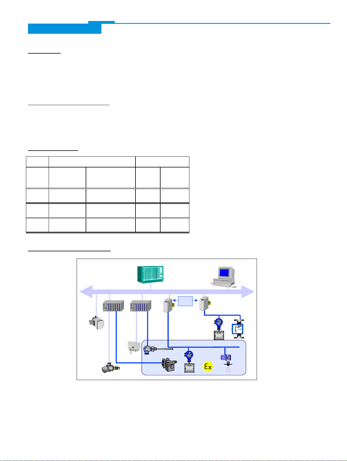
The PROFIBUS-PA is normally connected to a segment coupler, which, among other things,
carries out conversion to the PROFIBUS-DP. Here, it needs to be noted in particular that the
segment coupler is normally set to a fixed baud rate on the DP side.
Further information on the planning and Operation of PROFIBUS-PA networks is to be found
in the KROHNE brochure “PROFIBUS-PA networks”.
2.1 GSD File
All available GSD files of KROHNE devices – including those of the MFC 081 i or 085 i, of
course - are supplied together with each device. The GSD contains information that is needed
for project planning of the PROFIBUS-DP/PA communication network. The relevant data files
must be loaded into the project planning system/master system before start-up of the bus
system.
For example, the following applies to COMET 200 or COM PROFIBUS from Siemens:
•all GSD files (*.GSD) into the directory of the GSD files, e.g. *\GSD
•all BMP files (*.BMP) into the directory of the bit maps, e.g. *\BITMAPS
In STEP7, the GSD file is automatically copied into the respective directory with “install new
GSD” (in the HW-Config Menu: EXTRAS). After that, the bit map must be copied into the
directory *\SIEMENS\STEP7\S7data\Nsbmp. Following “catalogue updating” the device can
be placed in the project. This will then enable the cyclic communication (measured values and
status).
The MFC 081/085 i are supporting the entire PROFIBUS-PA profile V 3.0. All devices have
two ident-no. and two GSD files. Ident-no. “F701” belongs to the GSD file KROHF701.GSD
and includes the complete functionality of the mass flow meter. The use of the manufacturer
independent Ident-no. “9742” (GSD file “PA_9742.GSD”) allows the user an interchange with
other mass flow devices from other manufacturers.
PA_9742.GSD
The limited functionality of the GSD file includes four function blocks:
Mass flow rate, density, temperature and mass flow totalizer.
You need the PA_9742 to use this functionality. Before this, the communication has to be
projected and it has to be switched from “full functionality” to “interchangeable basic
configuration” by using a Master Class 2 Tool (IDENT_NUMBER_SELECTOR: Slot 0, Index
40 change byte value from 1 to 0). After this has been done, the device has to be projected by
using PA _9742.

Addendum to Operating and Instruction Manual for “Modis” Converters
KROHNE Ltd •Rutherford Drive •Park Farm Industrial Estate •Wellingborough •Northamptonshire •NN8 6AE •UK
Tel. +44 1933 408 500 •Fax +44 1933 408 501•WWW.KROHNE.com Page 10 of 18
KROHF701.GSD
KROHNE delivers the GSD with the entire device functionality, which is listed below:
Block Number Standard-Configuration KROHF701.GSD
Ident-No. F701 Address of the
“channel
parameter”
1 Mass Flow AI-FB ØxØ115
2 Density AI-FB ØxØ119
3 Temperature AI-FB ØxØ11D
4 Mass Totalizer Totalizer-FB ØxØ115
5 Volume Flow AI-FB ØxØ111
6 Percenta
g
e Mass or ° Brix AI-FB ØxØ139
7 Solid Flow AI-FB ØxØ141
8 Volume Totalizer Totalizer-FB ØxØ111
AI = Analog Input Function Block
FB = Function Block
Important Notes:
1. To project the PROFIBUS communication network, you have to allocate each of the
blocks to a function. On the PC-S7 from Siemens, this will be done with the Tool HW-
Config. It offers the functions which are described as follows:
2. It is possible to program an “empty block” on each block number. This means, that for this
block no data are transmitted in the cyclic data telegram.
3. There is NO Al block allowed on block position 4 and 8! Only totalizer block is here
allowed! That means the function “Analog Input (AI) is not possible. Beside the totalizer
functions is only the “empty block” allowed.
4. There is a choice between 4 different totalizer functions, which can be allocated to the
blocks 4 and/or 8. The meaning of the cyclic data transfer (Totalizer and Status) does
always correspond the meaning in section Meaning of the Measuring- and Status
Messages. The four functions are defined as follows:
Function “Totalizer” cyclic transfer of the totalizer with status to the master
Function “TOT_SetTot” cyclic transfer of the totalizer with status to the master +
cyclic control data from master to the device via the Bytes
SetTot
Function “TOT_Mode_Tot” cyclic transfer of the totalizer with status to the master +
cyclic control data from master to the device via the Bytes
ModeTot
Function “TOT_SetTot_ModeTot” cyclic transfer of the totalizer with status to the master +
cyclic control data from master to the device via the Bytes
SetTot and after that ModeTot
Both, the Byte SetTot and ModeTot are beeing sent cyclicly from Master to the device, by
inserting these bytes as output datas to the PLC configurator. The meaning of the control
bytes are as follows:

Addendum to Operating and Instruction Manual for “Modis” Converters
KROHNE Ltd •Rutherford Drive •Park Farm Industrial Estate •Wellingborough •Northamptonshire •NN8 6AE •UK
Tel. +44 1933 408 500 •Fax +44 1933 408 501•WWW.KROHNE.com Page 11 of 18
SetTot
SetTot =0: Totalizer is totalizing. If the value of SetTot changes from “1” or “2” to “0”
the totalizer starts from the actual (0 or Preset value).
SetTot =1: Totalizer will be reset to 0 and stays there until SetTot is switched to 0.
SetTot =2: Totalizer is set to the value of PresetTot. PresetTot can be written via a
acyclic master (totalizer in block 4 = Slot 4 Index 32; totalizer in block 8
Index 32).
SetTot >2: Is not allowed
ModeTot
ModeTot = 0 totalizer totalizes positive and negative values.
ModeTot = 1 totalizes only positive values.
ModeTot = 2 totalizes only negative values.
ModeTot = 3 totalizer is stopped, no totalization happens.
ModeTot >3 is not allowed
5. The standard block configuration can be changed, e.g. that density will be transferred in
block 1 instead of block 2. To do this, customer has to use a user tool, which can change
the “channel parameter” under the relative index 14, for totalizer function blocks under
index 12. In the above listed table, we have listed in the column “ Address of the “channel
parameter” the value, which you have to program in the channel parameter of the function
blocks.
6. Does the device include the options “volume concentration” or “° Baumé”, ° Brix and
NaOH, these values can be programmed via the channel parameters on a Al function
block. The value of the corresponding function block (relative Index 14) has to be
programmed 0x0135 for volume concentration or 0x013D for ° Baumé.
2.2 PROFIBUS-PA Profile
The MFC 081/085 i supports the PROFIBUS-PA Profile Version 3.0. Additionally, all relevant
parameters in the device are offered via the PROFIBUS-PA interface. The MFC 081/ 085
i
defines the following blocks:
•Six blocks Analog Input (AI): mass flow, density, temperature, volume flow, percentage
mass and solid flow. Optional volume concentration and ° Baumé can be provided.
•Two totalizer function blocks (TOT): totalized mass and totalized volume. As an option, the
solids can be totalized.
•One transducer block for Coriolis mass flow devices.
This block provides the parameters and functions defined in Profile 3.0, as well attached
are the values, which are not defined by the profile.
•One physical block.
This block contains the parameters defined in Profile 3.0.

Addendum to Operating and Instruction Manual for “Modis” Converters
KROHNE Ltd •Rutherford Drive •Park Farm Industrial Estate •Wellingborough •Northamptonshire •NN8 6AE •UK
Tel. +44 1933 408 500 •Fax +44 1933 408 501•WWW.KROHNE.com Page 12 of 18
2.3 Meaning of the Measuring- and Status Messages
By implementing devices in the PROFIBUS-Master by using the GSD, it is possible to
indicate, which measuring and totalizer messages will be transferred over the PROFIBUS. To
each values a status will be added. First, the 4 value byte (Float Format to IEEE Standard 754
Short Real Number) and then 1 status Byte will be transferred. That means that each
measuring or totalizing value is described with 5 byte and transmitted one after the other
according to the sequence which was projected over the GSD. If 4 function blocks have been
projected, 20 byte will be transmitted.
First an example of the float format:
Byte n Byte n+1 Byte n+2 Byte n+3
Bi
t7Bit6 Bi
t7Bit6 Bit7 Bit7
V
Z27262524232221202-
12-
22-
32-
42-
52-
62-
72-
82-
92-
10 2-
11 2-
12 2-
13 2-
14 2-
15 2-
16 2-
17 2-
18 2-
19 2-
20 2-
21 2-
22 2-
23
Exponent Mantisse Mantisse Mantisse
Example: 40 F0 00 00 (hex) = 0100 0000 1111 0000 0000 0000 0000 0000 (binary)
Formula: Value = (-1)VZ * 2 (Exponent - 127) * (1 + Mantisse)
Value = (-1)0 * 2 (129 - 127) * (1 + 2-1 + 2-2 + 2-3)
Value = 1 * 4 * (1 + 0,5 + 0,25 + 0,125)
Value = 7,5
The meaning of the status (unsigned integer) you will find in following table:
Qualit
yQuality-
Substatus Limits
Gr Gr Q
SQ
SQ
SQ
SQ
uQ
u
2726252423222120
0 0 = bad
0 1 = uncertain
1 0 = good (Non Cascade)
1 1 = good (Cascade) - not supported
Status = bad
0 0 0 0 0 0 = non-specific
0 0 0 0 0 1 = configuration error
0 0 0 0 1 0 = not connected
0 0 0 0 1 1 = device failure
0 0 0 1 0 0 = sensor failure
0 0 0 1 0 1 = no communication (last usable value)
0 0 0 1 1 0 = no communication (no usable value)
0 0 0 1 1 1 = out of service
Status = uncertain

Addendum to Operating and Instruction Manual for “Modis” Converters
KROHNE Ltd •Rutherford Drive •Park Farm Industrial Estate •Wellingborough •Northamptonshire •NN8 6AE •UK
Tel. +44 1933 408 500 •Fax +44 1933 408 501•WWW.KROHNE.com Page 13 of 18
0 1 0 0 0 0 = non-specific
0 1 0 0 0 1 = last usable value
0 1 0 0 1 0 = substitute-set
0 1 0 0 1 1 = initial value
0 1 0 1 0 0 = sensor conversion not accurate
0 1 0 1 0 1 = engineering unit violation (unit not in the
valid set)
0 1 0 1 1 0 = sub-normal
010111 =configurationerror
011000 =simulated value
011001 =sensorcalibration
Status = good (Non-Cascade)
1 0 0 0 0 0 = ok
1 0 0 0 0 1 = update event
1 0 0 0 1 0 = active advisory alarm (priority < 8)
1 0 0 0 1 1 = active critical alarm (priority > 8)
1 0 0 1 0 0 = unacknowledged update event
1 0 0 1 0 1 = unacknowledged advisory alarm
1 0 0 1 1 0 = unacknowledged critical alarm
101000 =initiate fail safe
101001 =maintenance required
Status = Limits 0 0 = ok
0 1 = low limited
1 0 = high limited
1 1 = constant
Please test the first two (Quality) to check the quality of the measuring value:
Good (non Cascade) measuring value is ok and can be used
Uncertain the measuring value can be used, although the accuracy is not
confirmed (e. g. measuring value is frozen or A/D-value is outside
of the valid range)
Bad the measuring value is not acceptable and cannot be used for
further processing.
Good (Cascade) will not be supported, because it is not applicable for the device
Diagnosis
If the internal diagnostic detects a error, additional information will be transmitted in the
Master. The meaning of this information are described in the GSD-file under
UNIT_DIAG_BIT(i).

Addendum to Operating and Instruction Manual for “Modis” Converters
KROHNE Ltd •Rutherford Drive •Park Farm Industrial Estate •Wellingborough •Northamptonshire •NN8 6AE •UK
Tel. +44 1933 408 500 •Fax +44 1933 408 501•WWW.KROHNE.com Page 14 of 18
3. Connection of Instruments on the PROFIBUS-PA system
3.1 Interconnection of devices in hazardous locations
We recommend that a PROFIBUS-PA network in the hazardous location be projected in
accordance with PTB’s FISCO model (see KROHNE brochure “PROFIBUS-PA networks”). In
that case, all connected electrical components (including the bus termination) must be
approved in conformity with the FISCO model.
3.2 Bus cable
The statements given in the FISCO model apply only provided the bus cable used meets the
following specifications: R´=15...150 Ohm/km; L´=0.4...1 mH/km; C´=80...200 nF/km.
3.3 Shielding and grounding
For optimum electromagnetic compatibility of systems it is extremely important that the
system components, and particularly the bus cables connecting the components, be shielded
and that such shields - if possible - form an unbroken cover, electrically speaking.
Hence it follows that, for use in non-hazardous duty systems , the cable shield should be
grounded as often as possible.
In “Ex“ systems with adequate equipotential bonding in the hazardous and non-hazardous
location along the entire Fieldbus installation, multiple grounding of the shield is also of
advantage.
Note: The use of twisted and shielded cables is strongly recommended, otherwise EMC
protection of the mass flow meter cannot be assured.
3.4 PROFIBUS-PA connection
Connect the bus cable as shown in
the figure.
•Connect the cable cores to
terminals D and D• .
•Polarity reversal will not have
any effect.
•The cable shield should be
connected with minimum length
to the FE functional ground.
•The equipotential bonding
conductor must be connected to
the device b
y
connectin
g
it to FE
functional ground
PROFIBUS-PA with current output:

Addendum to Operating and Instruction Manual for “Modis” Converters
KROHNE Ltd •Rutherford Drive •Park Farm Industrial Estate •Wellingborough •Northamptonshire •NN8 6AE •UK
Tel. +44 1933 408 500 •Fax +44 1933 408 501•WWW.KROHNE.com Page 15 of 18
DI
1
Power
Supply
Power
Supply
Fieldbus Current
Output Fieldbus
Current
Output
D I1DDII
Non-Ex-Version Ex-Version
4-20mA
U=8-30V
+-
Shield
PROFIBUS-
PA
4-20mA
U=8-30V
-+
Shield
PROFIBUS-
PA
4. Menu Settings for PROFIBUS-PA
The following settings need to be made for Operation of the MFC 081/ 85 i on a PROFIBUS-
PA network. Note, that the address can be set over the communication service “Set slave
address” from the master.
Function (Fct.) Description
3.8.4
LOCATION Tag name setting (measuring point no.) max. 10 characters
Characters assignable to each place:
A-Z 0-9 or "_" (blank character)
3.11.0 Text, measuring-point tag (max. 10 characters)
Characters assignable to each place:
A-Z 0-9 or "_" (blank character)
3.11.1
PROTOCOL •PROFI PA
3.11.2
ADDRESS Set address
Range: 00-126 for PROFIBUS-PA (default 126)
3.11.3
BAUD RATE BLOCKED

Addendum to Operating and Instruction Manual for “Modis” Converters
KROHNE Ltd •Rutherford Drive •Park Farm Industrial Estate •Wellingborough •Northamptonshire •NN8 6AE •UK
Tel. +44 1933 408 500 •Fax +44 1933 408 501•WWW.KROHNE.com Page 16 of 18
5. Technical Data
Hardware Software
Physical to IEC 61158-2 and the FISCO
model GSD GSD file supplied on diskette
Bus characteristic 9... 30 V; 0.3 A max.; 4.2 W max. Device profile complete implementation of
Profile B, V3.0
Base current 10 mA. Function blocks Function blocks (listed
units=default units)
mass flow [kg/s]
densit
y
[k
g
/l]
temperature [°K]
mass totalizer [k
g
]
volume flow [m3/h]
percenta
g
e mass [%sol/wt] or
°Brix [de
g
Brix]
solid flow [k
g
/s]
volume totalizer [m3]
FDE yes: separate fault disconnection
electronics provided. Optional Percentage volume [%vol]
° Baumé [degBaum hv]
Fault current 6 mA; (fault current = max.
continuous current – base
current).
Address range 0-126, default 126,
Starting current lower than the base current Operator control local display and operator
interface at device.
“Ex“ approval EEx ia IIC T6 or EEx ib IIC/IIB T6
in conformity with the FISCO
model
SAP’s 1; the number of Service
Access Points is typically equal
of the number of master class
2 tools
Connection independent of polarity

Addendum to Operating and Instruction Manual for “Modis” Converters
KROHNE Ltd •Rutherford Drive •Park Farm Industrial Estate •Wellingborough •Northamptonshire •NN8 6AE •UK
Tel. +44 1933 408 500 •Fax +44 1933 408 501•WWW.KROHNE.com Page 17 of 18
Ex Non-Ex
Supply voltage 24 V AC/DC (Switch mode power supply)
UN= 24 V DC +30% / -25%, 5W
UN = 24 V AC +10% / -15%, 5W
100 V AC...230 V AC + 10% / 15%, 10 V A
24 V AC/DC (Switch mode power supply)
UN= 24 V DC +30% / -25%, 5W
UN = 24 V AC +10% / -15%, 5W
100 V AC...230 V AC + 10% / 15%, 10 V A
Fuse rating IN<= 1.25 A IN<= 1.25 A
Outputs / inputs Module dependant Module dependant
Current output (IS)
Function All operating data programmable galvanically
isolated from supply, CPU and other outputs.
Passive (Current sink, EX
i
)
All operating data programmable
galvanically isolated from supply, CPU and
other outputs. Passive.
Current 4 – 20 mA 4 – 20 mA
Linearity 0.05% (reference 20 mA at 25°C) 0.05% (reference 20 mA at 25°C)
Temperature drift <= 100 ppm/°K (Typical 30ppm/°K) <= 100 ppm/°K (Typical 30ppm/°K)
Load US– 8V
<= 22 mA (US= external supply voltage) US– 8V
<= 22 mA (US= external supply voltage)
Supply 8 – 30 V 8 – 30 V
Connect ONLY to certified IS circuits with the
maximum values:
Ui = 30V, Ii = 250mA, Pi = 1W
Pulse output (IS) Not available
Function All operating data programmable galvanically
isolated from supply, CPU and other outputs.
Operation Passive, loop-powered
External supply
voltage 6 – 30V DC
Current Maximum 110 mA / 6 – 30 V DC
I high <= 900 µA (30 V)
I high <= 200 µA (8 V)
Saturation
voltage ≤2V @ I = 110mA
Frequency ≤1300Hz
Connect ONLY to certified IS circuits with the
maximum values:
Ui = 30V, Ii = 250mA, Pi = 1W
Status output Not available
Function All operating data programmable galvanically
isolated from supply, CPU and other outputs.
Operation Passive, loop-powered
External supply
voltage 6 – 30V DC
Current ≤110 mA
I high <= 900 µA (30 V)
I high <= 200 µA (8 V)
Connect ONLY to certified IS circuits with the
maximum values:
Ui = 30V, Ii = 250mA, Pi = 1W

Addendum to Operating and Instruction Manual for “Modis” Converters
KROHNE Ltd •Rutherford Drive •Park Farm Industrial Estate •Wellingborough •Northamptonshire •NN8 6AE •UK
Tel. +44 1933 408 500 •Fax +44 1933 408 501•WWW.KROHNE.com Page 18 of 18
Ex Non-Ex
Control input (IS) Not available
Function All operating data programmable galvanically
isolated from supply, CPU and other outputs.
Operation Passive, loop-powered
External supply
voltage 7 – 30V DC
Current ≤4.5 mA
Control signals 7-30V DC for HIGH
0-2V or open terminals for LOW
Connect ONLY to certified IS circuits with the
maximum values:
Ui = 30V, Ii = 250mA, Pi = 1W
PROFIBUS PA
Hardware See table above See table above
Software See table above See table above
Fieldbus
Foundation (IS) Pending Pending
Hardware Designed to ISA and IEC 1158-2 physical
layer. Standards applicable to type 121
device profile.
Connection: polarity independent
Connect ONLY to certified IS circuits
according to the FISCO model with the
maximum values:
Ui = 30V, Ii = 250mA, Pi = 1W
Designed to ISA and IEC 1158-2 physical
layer. Standards applicable to type 121
device profile.
Connection: polarity independent
Bus data: 9V – 32V; 11mA typical
Ambient
Temperature -20 to 65°C -20 to 65°C
This manual suits for next models
1
Table of contents
Other KROHNE Media Converter manuals

KROHNE
KROHNE UFC 400 Wiring diagram

KROHNE
KROHNE MFC 400 Wiring diagram

KROHNE
KROHNE H250 M40 ESK4-Basic User manual

KROHNE
KROHNE MAC 100 User manual

KROHNE
KROHNE IFC 070 User manual

KROHNE
KROHNE UFC 400 Wiring diagram

KROHNE
KROHNE IFC 010 K User manual

KROHNE
KROHNE IFC 090 K User manual

KROHNE
KROHNE ifc 300 User manual

KROHNE
KROHNE UFC 400 Wiring diagram