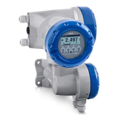
KROHNE MFC 400 Wiring diagram

Signal converter for mass flowmeters
Description of PROFINET IO interface
Description of PROFINET IO interfaceDescription of PROFINET IO interface
Description of PROFINET IO interface
Electronic Revision: ER 2.0.x
MFC 400
MFC 400MFC 400
MFC 400 Supplementary Instructions
Supplementary InstructionsSupplementary Instructions
Supplementary Instructions
© KROHNE 12/2017 - 4006097501 - AD MFC 400 Profinet R01 en
The documentation is only complete when used in combination with the relevant
documentation for the flow sensor.

CONTENTS
2
www.krohne.com 12/2017 - 4006097501 - AD MFC 400 Profinet R01 en
MFC 400
1 Introduction 4
1.1 Scope of the document..................................................................................................... 4
1.2 Used abbreviations ........................................................................................................... 4
1.3 Device description ............................................................................................................ 5
1.4 Special notes .................................................................................................................... 6
2 Technical data 7
2.1 PROFINET IO general information ................................................................................... 7
3 Electrical connections 8
3.1 Safety instructions............................................................................................................ 8
3.2 Shielding and grounding .................................................................................................. 8
3.3 PROFINET IO cable types ................................................................................................. 9
3.4 Electrical connection of PROFINET IO ........................................................................... 10
3.4.1 Overview of the PROFINET IO M12 connectors .................................................................... 10
3.4.2 Assembly of the M12 power supply connector with PROFINET IO ...................................... 11
3.4.3 Assembly of the M12 data connector with PROFINET IO..................................................... 11
3.4.4 Assembly of the terminals with PROFINET IO ..................................................................... 12
3.5 Topology of PROFINET IO networks............................................................................... 12
3.5.1 Point-to-point or star topology............................................................................................. 12
3.5.2 Line topology......................................................................................................................... 13
3.5.3 Ring topology......................................................................................................................... 13
4 Operation 14
4.1 System integration .........................................................................................................14
4.1.1 Default communication settings...........................................................................................14
4.1.2 Device discovery and identification (DCP signal) ................................................................. 14
4.2 Display menu .................................................................................................................. 15
4.3 Status LEDs on display................................................................................................... 15
4.3.1 Module status........................................................................................................................ 16
4.3.2 Network status...................................................................................................................... 16
4.4 Locking of configuration................................................................................................. 16
4.5 Interface description ......................................................................................................17
4.6 Data types and byte order .............................................................................................. 17
4.6.1 Float32................................................................................................................................... 17
4.6.2 Unsigned8 ............................................................................................................................. 17
4.6.3 Unsigned16............................................................................................................................ 17
4.7 Information & Maintenance (I&M).................................................................................. 18
4.7.1 I&M0 - Electronic type plate ................................................................................................. 18
4.7.2 I&M1 - Tags........................................................................................................................... 18
4.7.3 I&M2 - Installation date ........................................................................................................ 18
4.7.4 I&M3 - Descriptor ................................................................................................................. 19

4.7.5 I&M4 - Signature................................................................................................................... 19
4.8 Units of measurement.................................................................................................... 19

CONTENTS
3
www.krohne.com12/2017 - 4006097501 - AD MFC 400 Profinet R01 en
MFC 400
4.9 Start-up parameter configuration ................................................................................. 19
4.9.1 General.................................................................................................................................. 19
4.9.2 Process Input - Flow............................................................................................................. 20
4.9.3 Process Input - Density......................................................................................................... 20
4.9.4 Process Input - System Control ...........................................................................................20
4.9.5 Process Input - Concentration.............................................................................................. 21
4.9.6 Unit ........................................................................................................................................ 22
4.9.7 Totalizer 1.............................................................................................................................. 22
4.9.8 Totalizer 2.............................................................................................................................. 23
4.9.9 Status and Diagnostics ......................................................................................................... 23
4.10 Cyclic data..................................................................................................................... 24
4.10.1 Measurement blocks .......................................................................................................... 24
4.10.2 Totalizer blocks................................................................................................................... 24
4.10.3 Generic blocks..................................................................................................................... 24
4.10.4 Input data ............................................................................................................................ 25
4.10.5 Output data.......................................................................................................................... 26
4.11 Totalizer ........................................................................................................................ 26
4.12 Zero point calibration ................................................................................................... 27
4.13 Status information........................................................................................................27
4.13.1 Status coding - Device ........................................................................................................ 27
4.13.2 Status coding - Values ........................................................................................................ 28
4.13.3 Status coding - Sensor........................................................................................................ 28
4.14 Diagnosis ...................................................................................................................... 29
4.14.1 Diagnosis 1 .......................................................................................................................... 29
4.14.2 Diagnosis 2 .......................................................................................................................... 29
5 Notes 30

1
INTRODUCTION
4
MFC 400
www.krohne.com 12/2017 - 4006097501 - AD MFC 400 Profinet R01 en
1.1 Scope of the document
These instructions are supplementary to the standard handbook of the MFC 400 with ER 2.0.x
(refer to document MA MFC 400 from version R05). They provide additional information for the
devices when being operated and connected to a PROFINET IO network.
To ensure safety, please read this document carefully before installation and follow the
instructions herein.
1.2 Used abbreviations
AWG American Wire Gauge
DAP Device Access Point
DCP Dynamic Configuration Protocol
EIA/TIA Electronic Industries Alliance/Telecommunications Industry Association
EMC Electromagnetic Compatibility
EMI Electromagnetic Interference
GSD General Station Description
GSDML General Station Description Markup Language
ID unique Parameter ID
I&M Information & Maintenance
I/O Input/Output
IEC International Electrotechnical Commission
IEEE Institute of Electrical and Electronics Engineers
IP Internet Protocol
IRT Isochronous Real-Time
LFC Low Flow Cut-off
LLDP Link Layer Discovery Protocol
MAC Media Access Control
MIB Management Information Base
NIC Network Interface Controller
OUI Organizationally Unique Identifier
PE Protective Earth
PLC Programmable Logic Controller
PN PROFINET
PNIO PROFINET IO
RT Real-Time
SNMP Simple Network Management Protocol
t63 Time until 63% of the end value is reached for a step change.
For details refer to
Locking of configuration
on page 16, ID 61.
Table 1-1: Used abbreviations

INTRODUCTION
1
5
MFC 400
www.krohne.com12/2017 - 4006097501 - AD MFC 400 Profinet R01 en
1.3 Device description
The mass flowmeters are designed exclusively to directly measure mass flow rates, product
density and temperature as well to indirectly measure parameters such as the total volume,
concentration of dissolved substances and the volume flow rate.
Your measuring device is supplied ready for operation. The factory settings for the operating
data have been made in accordance with your order specifications.
The following versions are available:
•Compact version (the signal converter is mounted directly on the flow sensor)
•Remote version (electrical connection to the flow sensor via field current and signal cable)
Figure 1-1: Versions with bent tube
1 Compact version
2 Flow sensor with connection box
3 Field housing
Figure 1-2: Versions with straight tube
1 Compact version
2 Flow sensor with connection box
3 Field housing

1
INTRODUCTION
6
MFC 400
www.krohne.com 12/2017 - 4006097501 - AD MFC 400 Profinet R01 en
1.4 Special notes
INFORMATION!
This device is a Group 1, Class A device as specified within CISPR11:2009. It is intended for use in
industrial environment. There may be potential difficulties in ensuring electromagnetic
compatibility in other environments, due to conducted as well as radiated disturbances.
INFORMATION!
This device is a digital device used exclusively as an electronic control system utilised by a public
utility or in an industrial plant.
INFORMATION!
This PROFINET IO device is certified by the PROFIBUS Nutzerorganisation e.V.

TECHNICAL DATA
2
7
MFC 400
www.krohne.com12/2017 - 4006097501 - AD MFC 400 Profinet R01 en
2.1 PROFINET IO general information
PROFINET IO is an Ethernet based communications protocol. The device features two Ethernet
ports with an integrated industrial Ethernet switch (for details refer to
Assembly of the terminals
with PROFINET IO
on page 12).
The Ethernet standard 100BASE-TX is supported. Additionally, the device supports the following
features:
•Auto negotiation
•Auto crossover
•Auto polarity
The device itself supports PROFINET IO Conformance Class B (CC-B in table below).
•PROFINET IO version 2.3.3
•GSDML version 2.3.2
Device
Conformance Class CC-B
Basic function PROFINET IO with RT communication
PROFINET IO with RT communicationPROFINET IO with RT communication
PROFINET IO with RT communication
- Cyclic I/O
- Configuration parameters
- Alarms
- Network diagnostics via IP (SNMP)
- Topology information (LLDP) with LLDP-MIB
Cabling - IEC 61784-5-3
- Copper
Typical application - Factory Automation
- Process Automation
Table 2-1: Supported PROFINET IO Conformance Class

3
ELECTRICAL CONNECTIONS
8
MFC 400
www.krohne.com 12/2017 - 4006097501 - AD MFC 400 Profinet R01 en
3.1 Safety instructions
3.2 Shielding and grounding
•Only shielded cables with at least Category 5 must be used for PROFINET IO communication
(for details refer to
PROFINET IO cable types
on page 9), otherwise EMI protection of the
signal converter cannot be assured
•The cable shield must be grounded at least at one end
•If the cable shield is grounded at both ends, it shall have a connection to a common ground
DANGER!
Cables may only be connected when the power is switched off.
WARNING!
•
The device must be grounded in accordance with regulations in order to protect personnel
against electric shocks.
•
Follow the local health and safety regulations. Any work done on the electrical components of
the measuring device may only be carried out by properly trained specialists.
INFORMATION!
•
Special grounding instructions for the various flow sensors are contained in the handbook for
the signal converter.

ELECTRICAL CONNECTIONS
3
9
MFC 400
www.krohne.com12/2017 - 4006097501 - AD MFC 400 Profinet R01 en
3.3 PROFINET IO cable types
The decision for 2 or 4 pair cabling is depending on the application.
Decision criteria can be as follows:
2 pair cabling 4 pair cabling
Cable design 2 pair cabling shall be realised as one star-
quad or as 2 twisted pair design 4 pair cabling shall be realised as two star-
quad or as 4 twisted pair design
Devices in the network PROFINET IO devices PROFINET IO devices and also other
IT devices
Max. length 1100 m 100 m
Field of application Specialised and optimised for defined
PROFINET IO automation tasks Universal use of a PROFINET IO network for
PROFINET IO and other Ethernet
applications
Table 3-1: Decision criteria for 2 or 4 pair cabling
1From connection point to connection point. E.g. Ethernet switch to device, device to device, control system to device.
INFORMATION!
If the PROFINET IO device is used with 4 pair cabling only 2 pairs are connected.
Application Data cabling
Mode 2 pairs 4 pairs
Type RJ45 plug compatible or M12 D coded RJ45 plug compatible
Mandatory number of contacts 4 8
Rated voltage 57 VDC
Current (min.) 600 mA per contact at +70°C / +158°F
Outer cable diameter 5.5...8.0 mm / 0.22...0.31" 5.5...9.0 mm / 0.22...0.35"
Wire cross-section AWG 22 AWG 22...24
Wire diameter 1.4...1.6 mm / 0.055...0.0063" 1.0...1.6 mm / 0.039...0.0063"
Wire construction Solid / Stranded
Transmission performance ISO/IEC 11801 Edition 2.0 Amendment 2, Class D at least Category 5
Category (min.) ISO/IEC 11801 Edition 2.0 Connector Category 5
Shielding Yes
Cable strain relief IEC 61984
Mating cycles Min. 50
Table 3-2: Recommended cabling

3
ELECTRICAL CONNECTIONS
10
MFC 400
www.krohne.com 12/2017 - 4006097501 - AD MFC 400 Profinet R01 en
3.4 Electrical connection of PROFINET IO
3.4.1 Overview of the PROFINET IO M12 connectors
The PROFINET IO device will be supplied with at least one external M12 data connector. Optional
there is a second M12 data connector and a M12 power supply connector available.
•If one M12 data connector is assembled, PROFINET IO port 2 is available, only.
•If two M12 data connectors are assembled, PROFINET IO port 1 and 2 are available.
Standardised M12 connectors (IP66/67 or higher) must be used and are described in the
following standards: IEC 61076-2-101
INFORMATION!
The optional M12 power supply connector is only available for the 24 VDC version.
PROFINET IO with one M12 data connector PROFINET IO with two M12 data connectors
1–Cable gland (optional M12 power supply
connector)
2–not used
3–PROFINET IO port 2 connector
1–Cable gland (optional M12 power supply
connector)
2–PROFINET IO port 1 connector
3–PROFINET IO port 2 connector
Table 3-3: M12 data connector overview
INFORMATION!
•
Unused M12 connectors must be covered by the provided cap to protect the connector from
dust and humidity.
•
Straight M12 connectors are recommended.

ELECTRICAL CONNECTIONS
3
11
MFC 400
www.krohne.com12/2017 - 4006097501 - AD MFC 400 Profinet R01 en
3.4.2 Assembly of the M12 power supply connector with PROFINET IO
3.4.3 Assembly of the M12 data connector with PROFINET IO
Figure 3-1: PROFINET IO M12 power supply connector (male, A coded)
Number Description Colour
1L+ +24 VDC brown
2not connected
3not connected
4L- GND black
5PE/shield grey
Table 3-4: PROFINET IO M12 power supply connector pinout and colouring scheme
Figure 3-2: PROFINET IO M12 data connector (female, D coded)
Number Signal Colour
1TX+ yellow
2RX+ white
3TX- orange
4RX- blue
Table 3-5: PROFINET IO M12 data connector pinout and colouring scheme

3
ELECTRICAL CONNECTIONS
12
MFC 400
www.krohne.com 12/2017 - 4006097501 - AD MFC 400 Profinet R01 en
3.4.4 Assembly of the terminals with PROFINET IO
The PROFINET IO device will be equipped with either one or two external M12 connectors.
For details refer to
Overview of the PROFINET IO M12 connectors
on page 10.
The internal connection of the M12 connectors to the screw terminal is presented in the
following table.
3.5 Topology of PROFINET IO networks
3.5.1 Point-to-point or star topology
Devices in this topology have only one connection to the control system (point-to-point) or to an
Ethernet switch (star).
Connection terminals
AA- A+ BB- CC- DD-
PROFINET IO Port 2 Port 1
100BASE-TX RX+ RX- TX+ TX- TX+ TX- RX+ RX-
EIA/TIA 568A 1white/
orange orange white/
green green white/
green green white/
orange orange
EIA/TIA 568B 1white/
green green white/
orange orange white/
green green
2-pair/ star-quad
2white blue yellow orange yellow orange white blue
Table 3-6: Terminal connection of PROFINET IO
1If used with 4 pair wires, leave unused pairs unconnected
2Specified in PROFIBUS Nutzerorganisation e.V., "PROFINET Cabling and Interconnection Technology - Guideline for PROFINET v3.1"
INFORMATION!
Devices in this network topology only need one Ethernet port.
Devices with two Ethernet connectors can still be used (for details refer to Overview of the
PROFINET IO M12 connectors on page 10
).
Figure 3-3: Point-to-point or star topology

ELECTRICAL CONNECTIONS
3
13
MFC 400
www.krohne.com12/2017 - 4006097501 - AD MFC 400 Profinet R01 en
3.5.2 Line topology
Devices and control systems in this topology are connected to each other in line (daisy chain).
There is no need for an additional Ethernet switch to connect the devices.
3.5.3 Ring topology
Devices and control systems in this topology are connected to each other in line. Additionally the
first and the last device are connected to the control system building a ring. The control system
must support this topology. This topology is typically preferred if redundancy is required.
INFORMATION!
Devices in this network topology need two Ethernet ports to forward the data telegrams to the
next device. If the device is placed at the end of a line, then a device with only one Ethernet port is
sufficient. Devices with two Ethernet ports can be used (for details refer to Overview of the
PROFINET IO M12 connectors on page 10
).
Figure 3-4: Line topology
INFORMATION!
Devices in this network topology need two Ethernet ports.
Figure 3-5: Ring topology

4
OPERATION
14
MFC 400
www.krohne.com 12/2017 - 4006097501 - AD MFC 400 Profinet R01 en
4.1 System integration
A PROFINET IO General Station Description (PN-GSD) file is required for system integration.
The file contains a device description written in GSD Markup Language (GSDML).
The GSD file is available for download from the KROHNE website.
4.1.1 Default communication settings
Unless it is ordered with customised settings the device is shipped with the following default
settings:
4.1.2 Device discovery and identification (DCP signal)
To identify the device, the DCP signal service can be used. While a DCP signal is active the
Network Status LED is flashing yellow at 1 Hz (for details refer to
Network status
on page 16).
PROFINET IO version 2.3.3
Manufacturer ID 0x45 = 69 = KROHNE
Device ID 0x4512 = 17682 = MFC 400
GSD file GSDML-V2.32-KROHNE-MFC400-YYYYMMDD.xml
Table 4-1: Device description
Parameter Value Description
Device Name
(NameOfStation) Empty / not set
IP Address 000.000.000.000 Empty / not set
Subnet Mask 000.000.000.000 Empty / not set
Default Gateway 000.000.000.000 Empty / not set
Table 4-2: Default communication settings

OPERATION
4
15
MFC 400
www.krohne.com12/2017 - 4006097501 - AD MFC 400 Profinet R01 en
4.2 Display menu
A detailed description of the display menus and functions can be found in the standard product
documentation of the signal converter. Special settings concerning the PROFINET IO features
can be accessed through "Setup" (C4.x) menus.
4.3 Status LEDs on display
The local display has two status LEDs dedicated to the PROFINET IO interface.
Menu
number
Parameter Description
C4.x .1 MAC Address Device Shows the device MAC Address.
.2 MAC Address Port 1 Shows the MAC Address of Port 1.
.3 MAC Address Port 2 Shows the MAC Address of Port 2.
.4 IP Address Read or change IP Address.
.5 Subnet Mask Read or change Subnet Mask.
.6 Default Gateway Read or change Default Gateway.
.7 Information Shows the software version.
Table 4-3: Menu structure for PROFINET IO
INFORMATION!
The display shows only the permanent configuration of IP address, subnet mask and default
gateway. A temporary IP configuration from a DCP server is not shown on the display.
Figure 4-1: Location of the status LED indication on the display for a PROFINET IO device
1 MS - Module Status LED
2 NS - Network Status LED

4
OPERATION
16
MFC 400
www.krohne.com 12/2017 - 4006097501 - AD MFC 400 Profinet R01 en
4.3.1 Module status
The MS (Module Status) LED indicates the status of the PROFINET IO interface.
4.3.2 Network status
The NS (Network Status) LED indicates the PROFINET IO communication state.
4.4 Locking of configuration
The device provides a locking mechanism for the local display when a PROFINET IO connection is
active. The lock covers all parameters within the start-up parameters as well as totalizers and
sensor control (e.g. zero calibration).
To enable the lock, set "Use configuration by PN controller" and "Lock Local Display" in the
start-up parameters (for details refer to
General
on page 19).
The write lock will be activated as soon as the PROFINET IO connection is established.
Once the PROFINET IO connection is released, the write lock will be deactivated.
Colour / signal Description
Red, steady on Communication module failure.
Green, steady on Operating correctly.
Table 4-4: MS LED
Colour / signal Description
Yellow, flashing PROFINET DCP signal used for device identification.
Red, steady on No Ethernet link.
Green, flashing Ethernet link at least on one port but no active PROFINET IO connection.
Green, steady on Active PROFINET IO connection.
Table 4-5: NS LED
INFORMATION!
The lock jumper must not be used with the PROFINET IO communication option. Otherwise the
device signals a device failure.

OPERATION
4
17
MFC 400
www.krohne.com12/2017 - 4006097501 - AD MFC 400 Profinet R01 en
4.5 Interface description
The device has a static slot/subslot configuration that is shown in the following table.
4.6 Data types and byte order
The data transmitted over the PROFINET IO interface is classified by several data types
(according to IEC 61158-5) described in the following subsections.
4.6.1 Float32
Float32 is also known as REAL in PLC language (IEC 61131-3).
S = Sign, E = Exponent, M = Mantissa
For more details refer to the standard IEEE 754 for single precision floating point format.
4.6.2 Unsigned8
Unsigned8 is also known as USINT or BYTE in PLC language (IEC 61131-3). Data of this type may
to be interpreted as an unsigned integer (USINT) or bit-wise (BYTE) depending on context.
4.6.3 Unsigned16
Unsigned16 is also known as UINT or WORD in PLC language (IEC 61131-3). Data of this type
may to be interpreted as an unsigned integer (UINT) or bit-wise (WORD) depending on context.
Slot Subslot Name Ident No. Description
0Device Access Point 0x1 Standard PROFINET IO DAP with up to 2 ports.
32768 Interface 0xa
32769 Port 1 0xb
32770 Port 2 0xc
1Sensors 0x2 Module representing the sensor system.
1Sensor Data 0x2 I/O data, start-up records
Table 4-6: Static PROFINET IO slot/subslot mapping
Byte order on bus 0 1 2 3
IEEE 754 bits SEEE EEEE EMMM MMMM MMMM MMMM MMMM MMMM
Example Value = 1234.567
0x44 0x9A 0x52 0x25
Table 4-7: Data type Float32
Byte order on bus 0 1
Significance MSB LSB
Example Value = 1234
0x04 0xD2
Table 4-8: Data type Unsigned16

4
OPERATION
18
MFC 400
www.krohne.com 12/2017 - 4006097501 - AD MFC 400 Profinet R01 en
4.7 Information & Maintenance (I&M)
The device supports the I&M functions 0 to 4.
I&M0 provides standardised information about the device, the so-called electronic type plate.
I&M1 to I&M4 are typically used for storage of PROFINET IO engineering related information.
The following subsections describe all I&M tables in detail. The length specifies the number of
octets of each element.
4.7.1 I&M0 - Electronic type plate
I&M0 data is read-only.
4.7.2 I&M1 - Tags
I&M1 parameters can be changed by user.
4.7.3 I&M2 - Installation date
I&M2 parameters can be changed by user.
Name Length Description
MANUFACTURER_ID 20x45 = 69 = KROHNE
ORDER_ID 20 Combination of flow sensor and signal converter IDs
e.g. VN12345678CG43011N00
SERIAL_NUMBER 16 System serial number
e.g. G170000001101111
HARDWARE_REVISION 2 1
SOFTWARE_REVISION 4= Electronic revision
e.g. V202 = V2.0.2
REV_COUNTER 2Always 0
PROFILE_ID 20 = non-profile device
PROFILE_SPECIFIC_TYPE 20 = non-profile device
IM_VERSION 20x0101 = I&M version 1.1
IM_SUPPORTED 20x1E = I&M 1 to 4 supported
Table 4-9: Description of I&M0
Name Length Description
TAG_FUNCTION 32 Task or function of the device. This text is shown on the
local display, too.
TAG_LOCATION 22 Location of the device.
Table 4-10: Description of I&M1
Name Length Description
INSTALLATION_DATE 16 Date of installation or commissioning.
Table 4-11: Description of I&M2

OPERATION
4
19
MFC 400
www.krohne.com12/2017 - 4006097501 - AD MFC 400 Profinet R01 en
4.7.4 I&M3 - Descriptor
I&M3 parameters can be changed by user.
4.7.5 I&M4 - Signature
I&M4 parameters can be changed by user.
4.8 Units of measurement
The PROFINET IO interface provides unit codes according to the official PROFIBUS PA Profile for
Process Control Devices V3.02. The supported unit codes are listed in the GSD file.
4.9 Start-up parameter configuration
The "Sensor Data" submodule (ident number 2; for details refer to
Interface description
on page
17) provides a set of parameters, the so-called record data or start-up records, that can be used
for device parameterization during connection setup. The GSD file contains descriptions of the
record data. We recommend using typical PROFINET IO engineering tools, which are able to
conveniently display the complete record data as a list of parameters.
The following sections provide a list of all parameters within the record data. A unique
parameter ID is introduced in order to reference each parameter explicitly.
4.9.1 General
Name Length Description
DESCRIPTOR 54 Additional information.
Table 4-12: Description of I&M3
Name Length Description
SIGNATURE 54 Application specific signature.
Table 4-13: Description of I&M4
INFORMATION!
The selection of the units of measurement on the local display and the units of measurement on
PROFINET IO are independent and are not synchronized. The PROFINET IO units can be set via
the start-up parameter configuration.
ID Name Data type Remarks
0Use configuration by PN
controller Unsigned8 Yes - The following parameters will be applied.
No - The following parameters ID 1 to ID 74 will be ignored,
the device runs with previous configuration.
1Lock Local Display Unsigned8 Yes - The local display will be locked as long as a PROFINET
IO connection is established.
No - The local display is not locked. Device settings can be
modified through the local display during an active PROFINET
IO connection.
Table 4-14: Parameter group - General

4
OPERATION
20
MFC 400
www.krohne.com 12/2017 - 4006097501 - AD MFC 400 Profinet R01 en
4.9.2 Process Input - Flow
4.9.3 Process Input - Density
4.9.4 Process Input - System Control
ID Name Data type Remarks
2Flow Direction Unsigned8 Forwards (default), Backwards
3Operation Mode Unsigned8 Stop, Measuring (default), Standby
4Damping [s] Float32 Process noise damping for all flow measurements.
5Low Flow Cut-off (LFC) [%] Float32 Low flow cut-off threshold for all flow measurements relative
to nominal mass flow rate.
Zero flow will be reported if the actual flow is below this
threshold.
6Pipe Diameter [mm] Float32 Pipe diameter for flow speed calculation.
7Pressure Suppression LFC [%] Float32 Pressure suppression low flow cut-off threshold relative to
nominal mass flow rate.
8Pressure Suppression Time [s] Float32 Pressure suppression time.
Table 4-15: Parameter group - Process Input - Flow
ID Name Data type Remarks
9Density Mode Unsigned8 Process (default), Fixed, Referred, Standard
10 Fixed Density Float32 Density value for density mode "Fixed".
Unit: selected by ID 53
11 Referred Density Temperature Float32 Reference temperature for density mode "Referred".
Unit: selected by ID 54
12 Referred Density Slope Float32 Density slope for density mode "Referred".
Table 4-16: Parameter group - Process Input - Density
ID Name Data type Remarks
13 Function Unsigned8 Off (default), Set Flow to 0.
System control, used in order to set all flow variables to zero if
variable is exceeding min. or max. density/temperature.
14 Variable Unsigned8 Density, Temperature
15 Min. Density Float32 Minimum density for variable "Density".
Unit: selected by ID 53
16 Max. Density Float32 Maximum density for variable "Density".
Unit: selected by ID 53
17 Min. Temperature Float32 Minimum temperature for variable "Temperature".
Unit: selected by ID 54
18 Max. Temperature Float32 Maximum temperature for variable "Temperature".
Unit: selected by ID 54
Table 4-17: Parameter group - Process Input - System Control
Other manuals for MFC 400
1
Table of contents
Other KROHNE Media Converter manuals

KROHNE
KROHNE IFC 010 K User manual

KROHNE
KROHNE UFC 400 Wiring diagram

KROHNE
KROHNE IFC 090 K User manual

KROHNE
KROHNE MFC 081 Operating instructions

KROHNE
KROHNE ifc 300 User manual

KROHNE
KROHNE UFC 300 V2 Wiring diagram

KROHNE
KROHNE H250 M40 ESK4-Basic User manual

KROHNE
KROHNE IFC 050 User manual

KROHNE
KROHNE MAC 100 User manual

KROHNE
KROHNE UFC 400 Wiring diagram