Kroks ARINST ArSiG-S User manual


Signal generators ARINST ArSiG-S and ArSiG-R
2
CONTENT
1. PURPOSE.................................................................................................................................................3
2. SAFETY RULES FOR WORKING WITH THE DEVICE...........................................................................3
2.1. General safety requirements..............................................................................................................3
2.2. Additional safety requirements...........................................................................................................3
3. SPECIFICATIONS ....................................................................................................................................4
3.1. General specification..........................................................................................................................4
3.2. Output power level .............................................................................................................................5
3.3. Spectral purity ....................................................................................................................................5
3.4. Pulse modulation................................................................................................................................7
4. COMPLETENESS.....................................................................................................................................7
5. DEVICE DESIGN......................................................................................................................................8
6. DESCRIPTION AND OPERATION PRINCIPLE OF THE DEVICE..........................................................8
7. TURNING ON..........................................................................................................................................10
8. SCREEN INTERFACE............................................................................................................................10
9. FAST START...........................................................................................................................................12
10. DEVICE MENU .....................................................................................................................................12
10.1. Setting the output frequency..........................................................................................................12
10.2. Setting the output power level........................................................................................................12
10.3. Pulse signal modulation menu .......................................................................................................13
10.4. Signal output menu in sweep mode...............................................................................................13
10.4.1. Stepped sweep........................................................................................................................14
10.4.2. Sweep on list...........................................................................................................................15
10.5. User settings menu ........................................................................................................................16
10.6. Additional options menu.................................................................................................................17
10.7. Setting the time to automatically turn off the screen......................................................................18
10.8. External trigger control...................................................................................................................18
10.9. Using an external reference frequency source ..............................................................................18
10.10. Output frequency correction.........................................................................................................18
10.11. Offset of the output signal level value..........................................................................................18
10.12. Changing the theme of the on-screen interface...........................................................................19
11. CARE AND MAINTENANCE.................................................................................................................20
11.1. General care of the device.............................................................................................................20
11.2. Charge the battery..........................................................................................................................20
11.3. Battery replacement.......................................................................................................................20
11.4. Storage...........................................................................................................................................21
11.5. Transportation ................................................................................................................................21
11.6. The criterion of the limit state.........................................................................................................22
11.7. Utilization........................................................................................................................................22
12. POSSIBLE MALFUNCTIONS AND METHODS OF THEIR ELIMINATION .........................................23
13. WARRANTY..........................................................................................................................................24
APPLICATION A.ARINST ArSiG-S and ARINST ArSiG-R RF signal generators software update ...........25

Signal generators ARINST ArSiG-S and ArSiG-R
3
1. PURPOSE
1.1. Portable signal generators ARINST ArSiG-S and ARINST ArSiG-R are designed to generate
high-frequency signals in the range 1-6200 MHz. The devices are capable of sweeping the output signal,
both in frequency and in level. The generators have the ability to use an external highly stable signal
source as a reference.
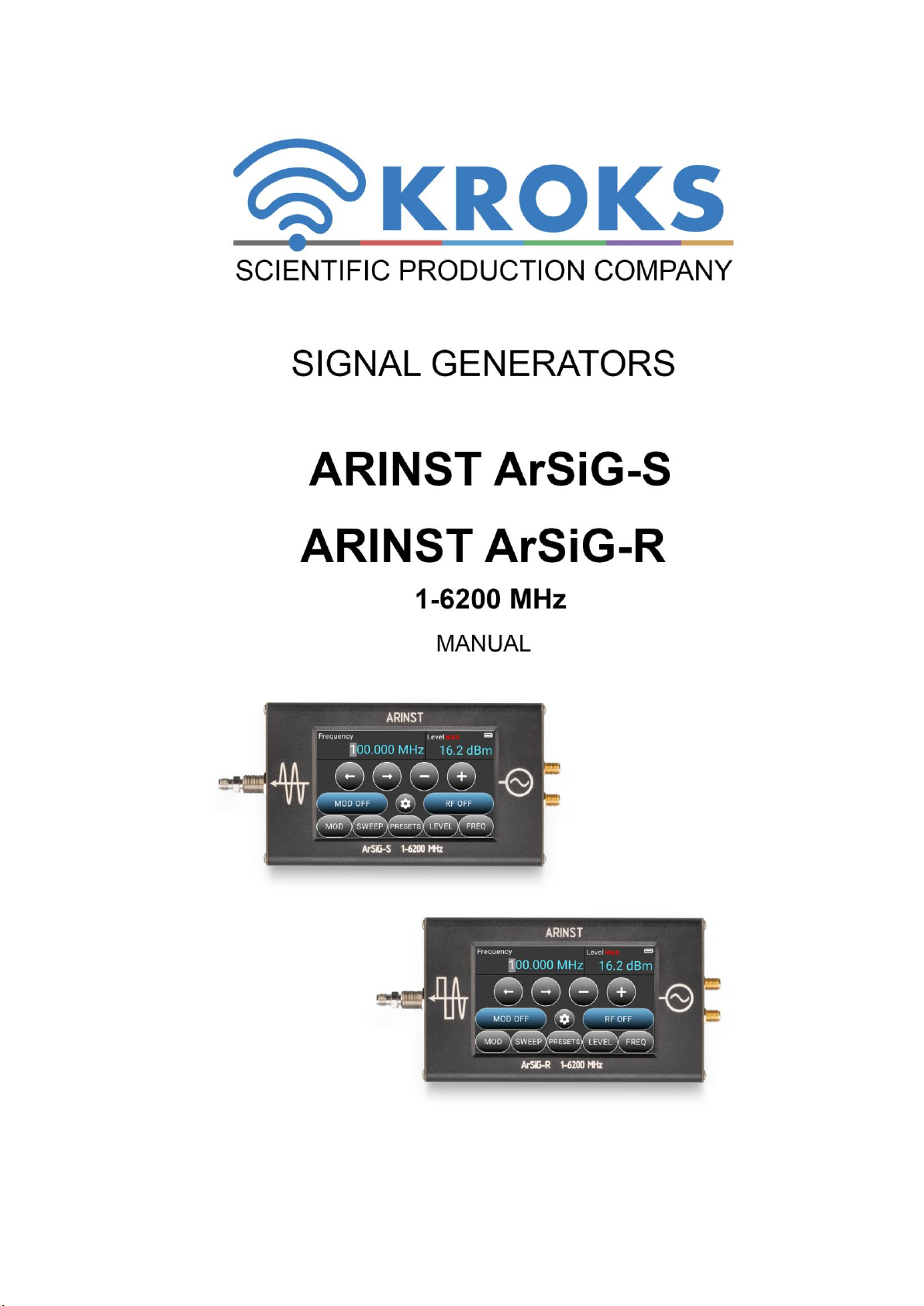
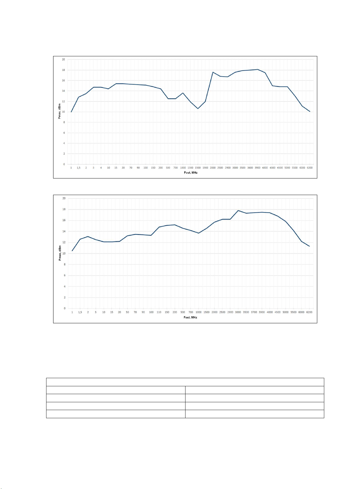
1.2. Generator ARINST ArSiG-S is a generator of sinusoidal signals in the entire operating frequency
range. The ARINST ArSiG-R generator generates rectangular signals in the frequency range up to 3000
MHz. In the range from 3000-6200 MHz, the device generates sinusoidal signals.
1.3. Generators play an important role in electrical and radio measurements. They are used to gener-
ate test signals for the development and debugging of various devices: amplifiers, filters, receiving and
transmitting paths, when measuring and analyzing antennas.
1.4. The devices are intended for amateur radio applications, as they are not a professional measuring
instrument. The built-in battery allows you to make measurements, both in the laboratory and in practical
conditions..
2. SAFETY RULES FOR WORKING WITH THE DEVICE
2.1. General safety requirements
2.1.1. Persons who have read this «Manual»and have been instructed in the rules of safe work with
electrical appliances are allowed to work with the device.
2.1.2. The risk of injury is possible when the charger is connected or disconnected from the electrical
network. Use serviceable power outlets and chargers.
2.1.3. To avoid damage to the wires and connectors of the device, do not hang anything on the wires,
paint over and glue the wires and connectors, disconnect the wires by pulling the cord.
2.1.4. Persons using the device are strictly prohibited: pass the device to strangers, disassemble and
carry out any repairs not agreed with the manufacturer, use a device with a damaged case.
2.1.5. If you find a fault, stop operation immediately and turn off the device.
2.1.6. If you need to leave your workplace, turn off the device and other devices. Do not leave the
working device unattended!
2.1.7. Do not use the device in hospitals. The use of the device near medical equipment is allowed on-
ly with the consent of the medical staff.
2.2. Additional safety requirements
2.2.1. Use the device only for its intended purpose. Read the purpose, device, and technical character-
istics of the device.
2.2.2. Avoid working in open spaces during snow or rain. High humidity and all types of liquid, getting
inside the device, can damage it.
2.2.3. Do not expose the device to very low or very high temperatures, exposure to extreme tempera-
tures can damage the built-in battery.
2.2.4. Do not use the device in areas with a corrosive or explosive environment. Aggressive vapors
can destroy the insulation, which can cause the device to fail.
2.2.5. Do not apply excessive force to the device's connectors, controls, or screen. Avoid bumps and
falls on the device. If the device falls, it may be damaged.
2.2.6. Do not disassemble or modify the device without the consent of the manufacturer or without the
instructions described in this manual. Incorrect self-intervention in the device will result in loss of warran-
ty. 2.2.7. Use chargers, cords, adapters, and other accessories recommended by the manufacturer.
2.2.8. When connecting other tools to the device, carefully read their purpose, technical characteris-
tics. Do not connect incompatible devices.
2.2.9. Maintenance and repair of the device must only be performed by the manufacturer or an author-
ized service center.

Signal generators ARINST ArSiG-S and ArSiG-R
4
3. SPECIFICATIONS
3.1. General specification
General technical characteristics of the device are shown in Table 1.
Table 1
Parameter
Value
ArSiG-S
ArSiG-R
Frequency range
1-6200 MHz
Output power level error1
±1 dB
Frequency resolution
3 kHz
Step of setting the output power level
0,1 dB
SSB phase noise @ 1GHz (carrier offset = 100 kHz)
-95,2 dBc/Hz
-110,1 dBc/Hz
Nominal output power level
+10 dBm
Minimum output power level
1-50 MHz
-20 dBm
-5 dBm
50-100 MHz
0 dBm
100-3000 MHz
-10 dBm
3000-5500 MHz
-10 dBm
-10 dBm
5500-6200 MHz
-20 dBm
-20 dBm
Output impedance
50 Ohm
Maximum DC Input Voltage
+25 V
Maximum input power
+10 dBm
Number of stored user settings
10
The number of stored sweep items in each list
50
Working temperature range
0 … +40°С
Screen diagonal
4”
Screen type
touch resistive
Screen resolution
800×480
Output port connector type
SMA female
External reference signal source
Connector type
SMA female
Input frequency range
10-40 MHz
Input signal level
maximum
+13 dBm
recommended
+5 ÷ +10 dBm
Input impedance
50 Ohm
External trigger
Connector type
SMA female
Maximum input voltage
+3,3 V
Power consumption and dimensions
Supply voltage
5 V
Power consumption
3,7 W
3 W
Maximum con-
sumed current, no
more
when charging the battery2
≤2 A
when working from USB with battery charging3
≤2 A
Battery capacity
5000 mAh
Time of continuous battery life4
4,5 h
5,5 h
Battery charge time
~ 3,5 h
Overall dimensions (L × W × H)
150×81×27 mm
Weight
0,4 kg
1
The measurement is performed after warming up the device for at least five minutes. The change in
ambient temperature from the moment of calibration to measurements should not exceed ± 3°С.
2
When connecting the device to a charger with an output current of at least 3A.
3
If your PC has a limit on the maximum current supplied to the USB port, the device will automatically
limit the maxi-mum charging current according to the current USB specification.
4
At an ambient temperature of 20±5°C after the battery is fully charged.

Signal generators ARINST ArSiG-S and ArSiG-R
5
3.2. Output power level
The graphs of the maximum output power level of the devices are shown in Figures 3.1 and 3.2.
Figure 3.1 –Maximum output power level of the ARINST ArSiG-S generator
Figure 3.2 –Maximum output power level of the ARINST ArSiG-R generator
3.3. Spectral purity
Measurements were made with an output power level of 0 dBm.
3.3.1. Broadband Non-harmonic Spurious spectral components
Table 2
ARINST ArSiG-S
Frequency, MHz
dBc
1-1900
< -75
1900-3000
< -72
3000-6200
< -60

Signal generators ARINST ArSiG-S and ArSiG-R
6
Table 3
ARINST ArSiG-R
Frequency, MHz
dBc
1-100
< -92
100-3000
< -70
3000-6200
< -60
3.3.2. Harmonics (2nd or 3rd harmonics, whichever is worse).
Table 4
Frequency, MHz
dBc
ArSiG-S
ArSiG-R
1
-25
-8
5
-35
-10,1
10
-36
-8,7
50
-36
-9,1
100
-36
-15,9
500
-34
-9
1000
-24
-4
2000
-16
-7,8
3000
-21
-21
4000
-31
-36
5000
-36
-36
6000
-40
-45
6200
-50
-47
3.3.3. Phase noise.
Table 5
Frequency, MHz
ARINST ArSiG-S
Offset from carrier
1 kHz
10 kHz
100 kHz
1 MHz
SSB phase noise, dBc/Hz
1
-88,1
-93,4
-95,1
-
10
-95,8
-96,5
-95,3
-123,1
100
-93,1
-94,9
-97,1
-121,6
1000
-90,3
-90,8
-95,2
-119,8
2000
-93,2
-87,9
-105,4
-129,4
3000
-84,4
-82,8
-100,8
-127,1
4000
-82,7
-84,1
-99,5
-128,4
5000
-79,8
-81,8
-96,1
-125,7
6000
-82,9
-77,5
-94,8
-123,1
6200
-82,3
-77,6
-91,8
-122,1

Signal generators ARINST ArSiG-S and ArSiG-R
7
Table 6
Frequency, MHz
ARINST ArSiG-R
Offset from carrier
1 kHz
10 kHz
100 kHz
1 MHz
SSB phase noise, dBc/Hz
1
-96,5
-118,3
-116,1
-
10
-97
-117,6
-116,5
-134
100
-91,9
-103,6
-111,1
-125,2
1000
-90
-95,4
-110,1
-132,1
2000
-91,1
-90,6
-105,6
-129,7
3000
-85,2
-86,7
-100,8
-125,6
4000
-84,3
-85,5
-100,5
-127,6
5000
-85,9
-82,3
-93,2
-125,4
6000
-81,2
-78,1
-93,5
-123,7
6200
-84,6
-78,4
-92,3
-123,2
3.4. Pulse modulation
Table 7
Pulse modulation
On/Off Ratio
Frequency, MHz
ArSiG-S
ArSiG-R
1
>70 dB (typ.)
>70 dB (typ.)
10
>70 dB (typ.)
>70 dB (typ.)
100
>70 dB (typ.)
>70 dB (typ.)
1000
70 dB (typ.)
>70 dB (typ.)
3000
70 dB (typ.)
>70 dB (typ.)
5000
60 dB (typ.)
30 dB (typ.)
6000
60 dB (typ.)
35 dB (typ.)
Minimum pulse width
1000 µs (typ.)
Minimum pulse period
2000 µs (typ.)
Maximum pulse period
1000000 µs (typ.)
4. COMPLETENESS
4.1. The delivery set of the device is shown in Table 8.
Table 8
Name
Quantity
ArSiG-S
ArSiG-R
RF signal generator ARINST ArSiG-S
1 pc.
-
RF signal generator ARINST ArSiG-R
-
1 pc.
USB 2.0 –Mini-USB cable
1 pc.
1 pc.
SMA (female) –SMA (female) adapter
2 pc.
2 pc.
Manual (product passport)
1 pc.
1 pc.
Package
1 pc.
1 pc.
Due to the continuous improvement of the device and software, the manufacturer reserves the
right to make changes to its technical characteristics and completeness.

Signal generators ARINST ArSiG-S and ArSiG-R
8
5. DEVICE DESIGN
5.1. The device structure is shown in Figure 5.1.
Figure 5.1 - External view of the device
1. RF output connector (RF OUT) intended for connection of the test devices and acts as a signal
source.
2. Left panel
3. Device body
4. Color resistive screen 4” serves to configure the device through the on-screen interface.
5. Right panel
6. Multifunctional button. Turns the device on and off by pressing and holding for about 2 seconds.
When pressed twice, it turns off the device screen. Tap the screen anywhere to turn it on.
7. Synchronization signal input / output (Trigger) (SYNK I/0).
8. External reference signal input (REF_IN).
9. Indicator STATUS. Lights up when the device is turned on.
10. Battery charging indicator CHARGE. It lights up when the battery is charging and when the de-
vice is powered by USB. When charging is finished, it goes off.
11. Connector Mini-USB. Serves for data transmission and battery charging of the device.
6. DESCRIPTION AND OPERATION PRINCIPLE OF THE DEVICE
Signal generators ARINST ArSiG-S and ARINST ArSig-R are based on a phase-locked loop (PLL)
synthesizer. The output signal is generated by dividing the set frequency of the voltage controlled oscilla-
tor (VCO). Comparing the obtained value with the frequency of the reference oscillator and adjusting the
VCO with a voltage proportional to the obtained difference. Structural diagrams of generators are shown
in Figures 6.1 and 6.2.
Generator ARINST ArSiG-S is a generator of sinusoidal signals in the entire operating frequency
range. Structurally, it is a generator with a support. The basic principle of the formation of the output sig-
nal in the low-frequency region of the frequency range is the multiplication of the signals of the two gen-
erators using a mixer. The mixer output is filtered to suppress higher harmonics and isolate the funda-
mental frequency. In the second subband, the signal from the synthesizer output is fed to the low-pass
filter to suppress the higher harmonics of the generated signal. In the third subband, the output of the
VCO of the frequency synthesizer is used to generate the output signal. The output of the VCO is a fun-
damental frequency with suppressed harmonics, so there is no additional filtering. Then the generated
signal is fed to a power amplifier. The amplified signal is fed to the output connector. Also, with the help of
a power coupler, the output power is measured and with the help of an automatic adjustment loop, the set
level is maintained.

Signal generators ARINST ArSiG-S and ArSiG-R
9
Figure 6.1 - Block diagram of the ARINST ArSiG-S signal generator
The ARINST ArSiG-R generator produces rectangular signals in the frequency range up to 3 GHz.
From 3 GHz, the output of the VCO of the frequency synthesizer is used to generate the output signal.
Thus, the output signal is sinusoidal. Then the generated signal is fed to the power amplifier. The ampli-
fied signal is fed to the output connector. Also, with the help of a power coupler, the output power is
measured and with the help of an automatic adjustment loop, the set level is maintained.
Figure 6.2 - Block diagram of the ARINST ArSiG-R signal generator
Both generators use a high-stability temperature-compensated oscillator with low phase noise as a ref-
erence frequency source.

Signal generators ARINST ArSiG-S and ArSiG-R
10
7. TURNING ON
Do not use the device outdoors during snowfall or rain. If the device is brought in during
the cold season from a cold room or from the street into a warm room, do not turn it on for a time
sufficient for the condensation from the device to evaporate.
Correlate the signal strength and the voltage applied to the ports with the maximum tech-
nical characteristics of the device specified in Table 1.
7.1. Make sure that the device has no external damage and the battery is charged. Charge the dis-
charged battery in accordance with clause 11.2.
7.2. Press and hold the button (6) for about 2 seconds. Switching on the device is confirmed by turning
on the STATUS indicator (9).
7.3. The device has a function of turning off the screen to save battery power. To turn off the screen
(4), press the button (6) twice. The device will continue to operate with the screen off. To turn on the
screen, tap it anywhere once.
7.4. To turn off the device, press and hold the button (6) for about 2 seconds. The screen (4) of the in-
strument will turn off and the instrument will turn off. Each time the device is turned off, the current user
settings are recorded in non-volatile memory, which allows you to avoid configuring the device when you
turn it on again.
8. SCREEN INTERFACE
On the screen of the device there are information areas and interactive buttons for controlling the de-
vice.
Figure 8.1 –Screen interface of the device
8.1. The information areas of the screen display information about the current settings and status of
the device.
8.1.1. Built-in battery status indicator:
indicator in the form of a spark (lightning) - the battery is being charged;
the battery indicator symbol is completely filled with white –the battery is fully charged;
the indicator symbol in the form of a white outline of the battery –the battery is low, you need
to charge it;
the device displays a message about a critical charge level –the battery is completely dis-
charged, the device will automatically turn off.
8.1.2. Frequency:
The user-defined signal frequency is displayed. Frequency setting is carried out in the range 1-6200
MHz.

Signal generators ARINST ArSiG-S and ArSiG-R
11
8.1.3. Signal power level (Level):
The set output power level is displayed in dBm, dBV, dBμV;
The maximum possible signal power level with the specified parameters. Indicated by the
symbol MAX. This indication informs that a further increase in power for the current frequency
is impossible.
8.2. Interactive interface control buttons are located under the information areas (Figure 8.1):
8.2.1. Signal frequency setting buttons:
and –moving the cursor over the digits of the set frequency value or output sig-
nal power level;
and –decrease or increase in the frequency or power level of the output signal.
8.2.2. Function buttons:
/ –Disabled / enabled signal modulation;
/ –Disabled / enabled supply of the output signal
to the RF OUT connector.
8.2.3. The buttons of the main menu of the device:
–menu for setting the pulse modulation of the output signal;
–menu for setting the output signal in the sweep mode;
–menu for saving user settings;
–setting the power level of the output signal;
–setting the frequency of the output signal.
–menu of additional settings of the device.

Signal generators ARINST ArSiG-S and ArSiG-R
12
9. FAST START
9.1. Turn on the device according to section 7.
9.2. Set the desired output frequency in the FREQ menu. For more information about setting the out-
put frequency, see section 10.1.
9.3. In the LEVEL menu, set the output power level. For more information about setting the output
power level, see section 10.2.
9.4. Connect the test device to the RF OUT (1) connector. Turn on the output signal by pressing the
RF OFF button.
9.5. To test the device with a pulse-modulated signal, set the desired parameters in the MOD menu.
For more information about setting parameters in the pulse modulation menu, see section 10.3.
9.6. The pulse-modulated signal is sent by pressing the MODE OFF button in the MOD menu.
9.7. To output the signal in sweep mode, make the SWEEP menu settings. For more information, see
section 10.4.
9.8. Save the instrument settings in the PRESETS menu in accordance with section 10.5.
10. DEVICE MENU
10.1. Setting the output frequency
10.1.1. To set the output frequency, press the button on-screen interface of the device.
10.1.2. In the submenu that opens (Fig. 10.1), enter a numeric value for the output frequency and click
one of the units of measurement buttons. To delete erroneous values, clickDel. To exit the menu
without entering values, press BACK.
Figure 10.1 –Input of the output signal frequency
10.1.3. Adjustment and change of the output signal frequency is carried out using the buttons of the
screen interface (see section 8.2.1.).
10.2. Setting the output power level
10.2.1. To set the power level of the output signal, press the button of the instrument's on-
screen interface.
10.2.2. In the submenu that opens, enter the numerical value of the output signal power level and
press one of the unit buttons.
10.2.3. Adjustment and change of the output signal power is carried out using the buttons of the
screen interface (see section 8.2.1.).
The power level of the output signal may be lower than the value set by the user, as it depends on the
current frequency. In the Level information area, the maximum possible signal power value for the current
settings MAX is displayed, as shown in Figure 8.

Signal generators ARINST ArSiG-S and ArSiG-R
13
10.3. Pulse signal modulation menu
10.3.1. Enter the pulse modulation menu MOD by pressing the button on the screen of the
device. The menu for setting the pulse modulation of the output signal is shown in Figure 10.2.
Figure 10.2 –Pulse modulation menu
10.3.2. Each button in the pulse modulation menu has its own purpose:
Pulse period –the pulse period. Set by the user in the range from 2000-1000000 μs;
Pulse width –pulse width. Set in the range 1000-1000000 μs;
Pulse freq –pulse repetition rate. Value range 1-500 Hz;
Duty cycle –fill factor. Depends on the set values of the period and pulse width;
MOD OFF / MOD ON –modulation off / on;
BACK –exit the menu.
10.3.3. The parameters are set by entering a numerical value in the opened submenu, as shown in
Figure 10.3. Enter a numeric value and click Input. To delete erroneous values, click Del. To exit
the menu without entering values, press BACK.
Figure 10.3 –Entering parameters
Pulse repetition rates Pulse freq and fill factor Duty cycle depend on the set period values Pulse pe-
riod and Pulse width.
10.4. Signal output menu in sweep mode
The device implements two methods of signal sweep:
Step sweep in frequency and / or power level of the output signal;
Sweep according to the list of frequency and / or power of the output signal.

Signal generators ARINST ArSiG-S and ArSiG-R
14
10.4.1. Stepped sweep
A step sweep provides a linear change in frequency and / or power level from one selected value to
another, delaying at each step for a time set in the menu. The sweep can be performed in the direction of
increasing, decreasing the value, or controlled by a trigger.
10.4.1.1. Enter the signal output menu in SWEEP mode by pressing the button. on the de-
vice screen. The signal output menu in the sweep mode is shown in Figure 10.4.
Figure 10.4 –Signal output menu in sweep mode
10.4.1.2. Purpose of the menu buttons:
Frequency setting buttons Frequency:
Start –setting the starting frequency;
Stop –setting the final frequency;
Step –sweep frequency step.
The larger the sweep frequency step, the fewer the number of points in the frequency interval and
the less time it takes to cycle. On the contrary, the smaller the frequency step, the more points and the
longer the process takes.
Buttons for setting steps Steps:
Step time –sweep step delay time;
Points –quantity of points.
After setting the start and final frequency and sweep step, set the sweep step delay time.
Buttons for setting the output power level Level:
Start –setting the initial value of the power level;
Stop –setting the final value of the power level;
Step –power level change step.
SWP OFF / SWP ON –sweep off / on;
BACK –exit the menu.
10.4.1.3. Select from the drop-down list:
Sweep freq –frequency sweep. The output power setting buttons are not available.
Sweep level –sweep by signal power level. Frequency setting buttons are not available.
Sweep freq & level –frequency sweep and output signal power level.
10.4.1.4. Turn on the sweep by clicking the button SWP OFF. The enabled scan mode is displayed by
the green button SWP ON.

Signal generators ARINST ArSiG-S and ArSiG-R
15
10.4.2. Sweep on list
The list sweep allows you to enter the frequency and power of the output signal at various intervals in
any order.
10.4.2.1. Enter the signal output menu in SWEEP mode by pressing the button. on the de-
vice screen. The signal output menu in the sweep mode is shown in Figure 10.5.
10.4.2.2. Select from the dropdown list:
Sweep freq by list –list of steps by frequency;
Sweep level by list –list of steps by signal power level;
Sweep freq & level by list –list of steps by frequency and power level.
The device can store up to 50 sweep elements in each list.
Figure 10.5. –Menu for creating a list of sweeps
10.4.2.3. Buttons for working with the list of sweeps:
- add the sweep element to the list. Go to the menu "Add new sweep record". New
sweep entry (Fig. 10.6);
- edit the selected element of the sweep;
- remove the selected sweep item from the list;
Moving through the list of unfolding elements is carried out using the buttons and
;
SWP OFF / SWP ON –sweep off / on;
BACK –exit from the menu.
10.4.2.4. Purpose of the menu buttons "Add new sweep record" New sweep entry (Fig. 10.6):
Freq –setting the frequency in the range 1-6200 MHz. Option not available when selecting the list
Sweep level by list;
Step time –setting step time;
Level –setting the power level of the output signal in the sweep. Option not available when selecting
the list Sweep freq by list.
OK –create a sweep item in the list.
Cancel –refusing to create a sweep item in the list.

Signal generators ARINST ArSiG-S and ArSiG-R
16
Figure 10.6 –New sweep entry menu
10.5. User settings menu
10.5.1. To enter the PRESETS user settings menu, click on the device screen. The user
settings menu is shown in Figure 10.77.
Figure 10.7 –User settings menu
10.5.2. User settings menu buttons:
-Save the current settings. Go to the menu to assign the name of the setting (Figure
10.8);
- edit the name of the highlighted custom setting. Go to the menu to change the name
of the setting;
-remove the selected setting from the list;
You can move through the list of settings using the buttons and ;
LOAD –loading a dedicated custom setting;
BACK –exit from the menu.

Signal generators ARINST ArSiG-S and ArSiG-R
17
Figure 10.8 –Assigning a name to a new user setting
10.5.3. Enter a name for the custom setting using the instrument's on-screen keyboard and press the
button Input. To delete erroneous values, click Del. To exit the menu without entering values,
press ×Exit. Up to 10 user settings can be stored in the device memory.
10.5.4. The name of an existing user setting is edited in the same way as in section 10.5.3.
10.5.5. Download the selected setting by clicking LOAD.
10.6. Additional options menu
10.6.1. Enter the additional Settings menu by pressing the button on the device screen. The
additional options menu is shown in Figure 10.9.
Figure 10.9 –Menu of additional options
9.6.2. This section of the menu contains options:
information about the device (device id, firmware version) - button ;
setting the time to automatically turn off the screen - Screen auto-off;
external trigger control - External trigger;
enabling the step from an external reference source - External oscillator;
output signal frequency adjustment - Int. osc. correction;
offset of the output signal level value Level offset;
changing the theme of the interface Theme.
For a detailed description of the use of these options, see sections 10.7, 10.8, 10.9, 10.10, 10.11, and
10.12.
BACK –exit from the menu.

Signal generators ARINST ArSiG-S and ArSiG-R
18
10.7. Setting the time to automatically turn off the screen
10.7.1. Enter the Settings advanced options menu by clicking on the device screen (Fig. 10.9).
10.7.2. Set the timer to automatically turn off the screen Screen auto-off after 1, 5 or 10 minutes from
the moment there is no interaction between the user and the controls of the device. This setting allows
you to save a lot of battery power. If you do not need to turn off the display of the device after a certain
period of time, select the parameter Never. Setting the time of automatic shutdown of the device screen
is made by "scrolling" the values.
The device continues to work after the screen is turned off, the STATUS indicator is on. Tap anywhere
on the screen to turn it on.
10.8. External trigger control
To synchronize measurements using several instruments, use the SYNK I / 0 signal connector located
on the right panel of the generator (Fig. 5.1). The connector is used both as an input and as an output of
the synchronization pulse.
10.8.1. Enter the additional Settings menu by pressing the button on the device screen (Fig.
10.9). By default, the External trigger control option is disabled Disabled.
10.8.2. To use the generator as a master device and send a control pulse from the SYNK I / 0 con-
nector, select the Master mode in the drop-down menu. If the generator is used as a controlled device
and must receive a control pulse from the master device on the SYNK I / 0 connector, select the Slave
mode from the drop-down menu.
The maximum input voltage applied to the SYNC I / O port is + 3.3V.
10.9. Using an external reference frequency source
The device can use both an internal and an external signal as a reference signal. The external refer-
ence signal is fed to the REF IN input located on the right panel of the generator (Fig. 5.1).
10.9.1. Enter the additional Settings menu by pressing the button on the device screen (Fig.
10.9). Switching between the external and internal sources of the reference signal is performed by the
“slider” of the External oscillator. Set the frequency of the external reference signal.
The maximum allowable power of the external input signal is +13 dBm. It is recommended to
apply a signal with a power of no more than +10 dBm to the input of the device.
10.10. Output frequency correction
The output frequency may differ slightly from the output frequency of the reference instrument. Adjust
the generator output frequency to match the frequency of the reference instrument.
10.10.1. Enter the additional Settings menu by pressing the button on the device screen (Fig.
10.9). The input signal frequency adjustment mode is enabled by the Int. osc. correction slider. Set the
actual frequency of the output signal. The difference between the current frequency value and the input
reference value should not exceed ±0.1% (1000 ppm) of the current frequency. Otherwise, a message
appears stating that this adjustment cannot be applied.
10.11. Offset of the output signal level value
Offsetting the value of the output signal level allows you to compensate for the effect of a device con-
nected to the generator output and changing the output power level.
The power level offset option allows a constant value to be applied to the displayed level, thereby
compensating for loss or gain from the connected device. In this case, the displayed power level will cor-
respond to the actual power level at the output of the connected device.

Signal generators ARINST ArSiG-S and ArSiG-R
19
10.11.1. Enter the additional Settings menu by pressing the button on the device screen (Fig.
10.9). The power level offset of the output signal is enabled by the slider Level offset. Set the power level
offset value. When connecting an attenuator, use negative offset values, such as -10, -20, etc., and when
connecting an amplifier, use positive values, such as +10, +20, etc.
10.11.2. The value of the power level offset is shown in parentheses in the power field of the device
(Figure 10.10).
Figure 10.10 –Signal power level offset enabled
10.12. Changing the theme of the on-screen interface
The device has 40 pre-installed on-screen interface themes for individual customization.
10.12.1. Enter the additional Settings menu by pressing the button on the device screen (Fig.
10.9). Switching the themes of the on-screen interface is carried out using the buttons and .
10.12.2. When the slider «Show buttons» is enabled (Show btns), buttons for switching the themes of
the on-screen interface and displayed on the main screen of the interface.

Signal generators ARINST ArSiG-S and ArSiG-R
20
11. CARE AND MAINTENANCE
11.1. General care of the device
11.1.1. Maintenance consists in maintaining the device in working order, regularly carrying out preven-
tive maintenance.
11.1.2. Wipe the connectors of the test ports with a soft cloth or a brush dampened in rectified ethyl
alcohol, not allowing alcohol to get on the surfaces of dielectrics.
11.1.3. Clean the body of the device from dirt with a soft cloth dampened with soapy water or wet
household wipes. The penetration of liquids into the housing of the device is not allowed!
Do not use solvents based on alcohol or petroleum products to clean the screen and body
of the device! These liquids can damage the outer coating of the screen and the case of the prod-
uct.
11.2. Charge the battery
11.2.1. It is recommended to use a stabilized power supply with an output voltage of 5V and a current
of at least 1000 mA to charge the battery.
The device has an intelligent system for determining the maximum charging current depending on the
available power source. When the charger is connected, the maximum charging current is automatically
determined. To reduce the charging time of the built-in battery, it is recommended to use industrial power
supplies (chargers) with a maximum output current of 3 A as a charger.
11.2.2. Соедините USB-кабелем из комплекта поставки Mini-USB разъём прибора (11) с USB-
разъёмом блока питания или USB-портом ПК.
11.2.3. The CHARGE indicator (10) lights up while the battery is being charged. The battery charging
process will take about 3.5 hours. When charging is complete, the CHARGE indicator (10) will turn off.
The device is allowed to operate while the battery is charging, provided that the power supply is capable
of providing an output current of at least 1500 mA. If the charger or the USB port of the PC is not able to
provide the current required for the operation of the device and charging the battery, the device will auto-
matically reduce the charging current until the battery is completely charged.
11.3. Battery replacement
11.3.1. After a certain period, the capacity of the Li-Ion battery is reduced, and long-term use of the
device without recharging becomes difficult.
11.3.2. Replacing the battery is necessary when the following symptoms occur:
the battery charges very quickly and discharges very quickly;
the battery charges for a very long time (more than 10 hours);
the battery does not accept charge;
the device does not turn on offline (with the cord disconnected from the charger).
11.3.3. To replace, you must purchase a new Li-Ion battery with an operating voltage of 3.7 V, a ca-
pacity of at least 5000 mA and dimensions of not more than: height 7 mm, length 90 mm, width 60 mm.
When purchasing and installing a battery with a capacity other than the one installed by the device
manufacturer, it is necessary to take into account the fact that the battery charging time will also change
up or down.
Attention! When using a battery of another capacity, the correspondence of the displayed
charge level of the battery on the device screen to the real value is not guaranteed.
Attention! To replace the battery, you will need to disassemble the device. Ensure that you
have the necessary tools, knowledge, and qualifications sufficient to carry out an independent
repair of the device. With a lack of experience and qualifications, contact specialists with relevant
qualifications.
This manual suits for next models
1
Table of contents
Other Kroks Measuring Instrument manuals
Popular Measuring Instrument manuals by other brands

Heska
Heska Element COAG Operator's guide

Elementar Analysensysteme GmbH
Elementar Analysensysteme GmbH vario EL cube operating instructions

Nivetec
Nivetec Micronics U1000-HM user manual

Gossen MetraWatt
Gossen MetraWatt LonWorks ENERGYMID U228 W1 Series Interface description

Withings
Withings Aura quick start guide

RADWAG
RADWAG PUE CY10 operating manual