manuals.online logo
Brands
  1. Home
  2. •
  3. Brands
  4. •
  5. Krom Schroder
  6. •
  7. Switch
  8. •
  9. Krom Schroder DG B Series User manual

Krom Schroder DG B Series User manual

DK S N P GR
➔www.docuthek.com
D GB F NL I E
TR CZ PL RUS H
Cert. version 09.15
© 2016 Elster GmbH · Edition 09.16
Operating instructions
D
GB
F
NL
I
E
GB-1
03251234
Translation from the German
Pressure switches for gas
DG..B, DG..U
Please read and keep in a safe place
Please read through these instructions
carefully before installing or operating. Following the
installation, pass the instructions on to the operator.
This unit must be installed and commissioned in accord-
ance with the regulations and standards in force. These
instructions can also be found at www.docuthek.com.
Explanation of symbols
• , 1 , 2 , 3 ... = Action
▷= Instruction
Liability
We will not be held liable for damage resulting from
non-observance of the instructions and non-com-
pliant use.
Safety instructions
Information that is relevant for safety is indicated in
the instructions as follows:
DANGER
Indicates potentially fatal situations.
WARNING
Indicates possible danger to life and limb.
CAUTION
Indicates possible material damage.
All interventions may only be carried out by qualified
gas technicians. Electrical interventions may only be
carried out by qualified electricians.
Conversion, spare parts
All technical changes are prohibited. Only use OEM
spare parts.
Changes to edition 03.15
The following chapters have been changed:
– Checking the usage
– Installation
– Adjustment
– Technical data
– Certification
Checking the usage
Gas pressure switches DG for monitoring increasing
and decreasing gas or air pressure.
Positive pressure Negative pressure
DG..B Gas, air, flue gas –
DG..U Gas, air, flue gas Air, flue gas
This function is only guaranteed when used within the
specified limits– see page3 (Technical data). Any
other use is considered as non-compliant.
Type code
Code Description
DG Pressure switch for gas
6 – 500 Max. setting in mbar
B
U
Positive pressure
Positive pressure/Negative pressure
GWith gold-plated contacts
-3
-4
-5
-6
-9
Electrical connection
via screw terminals
via screw terminals, IP 65
4-pin plug, without socket
4-pin plug, with socket
4-pin plug, with socket, IP 65
K2
T
T2
N
Red/green pilot LED for 24 V DC/AC
Blue pilot lamp for 230 V AC
Red/green pilot LED for 230 V AC
Blue pilot lamp for 120 V AC
SOnly for oxygen and ammonia
AExternal adjustment
Part designations
1
2
3
4
Type label
DG
CE – 0085AP0467
2
13
D-49018 Osnabrück, Germany
Safety
1Upper housing section
with cover
2Lower housing section
3Hand wheel
4M16 cable gland
Max. inlet pressure =
withstand pressure,
mains voltage,
ambient
temperature,
enclosure:
see type label.
GB-2
D
GB
F
NL
I
E
Installation
CAUTION
Please observe the following to ensure that the DG
is not damaged during installation and operation:
– Continuous operation with gases containing
more than 0.1 %-by-vol. H2S or ozone con-
centrations exceeding 200 µg/m³ accelerate
the ageing of elastomer materials and reduce
the service life.
– Use approved sealing material only.
– Check max. ambient temperature – see
page3 (Technical data).
– When using silicone tubes, only use silicone
tubes which have been sufficiently cured.
– Vapours containing silicone can adversely affect
the functioning of electrical contacts.
– Condensation or vapours containing silicone
must not be allowed to get into the housing.
At subzero temperatures malfunctions/failures
due to icing can occur.
– When installing outdoors, place the DG in a
roofed area and protect from direct sunlight
(even IP65 version). To avoid condensation, a
cover with pressure equalization element (Order
No.74923391) can be used.
– Avoid strong impact on the unit.
– In case of highly fluctuating pressures, install a
restrictor orifice (Order No.75456321).
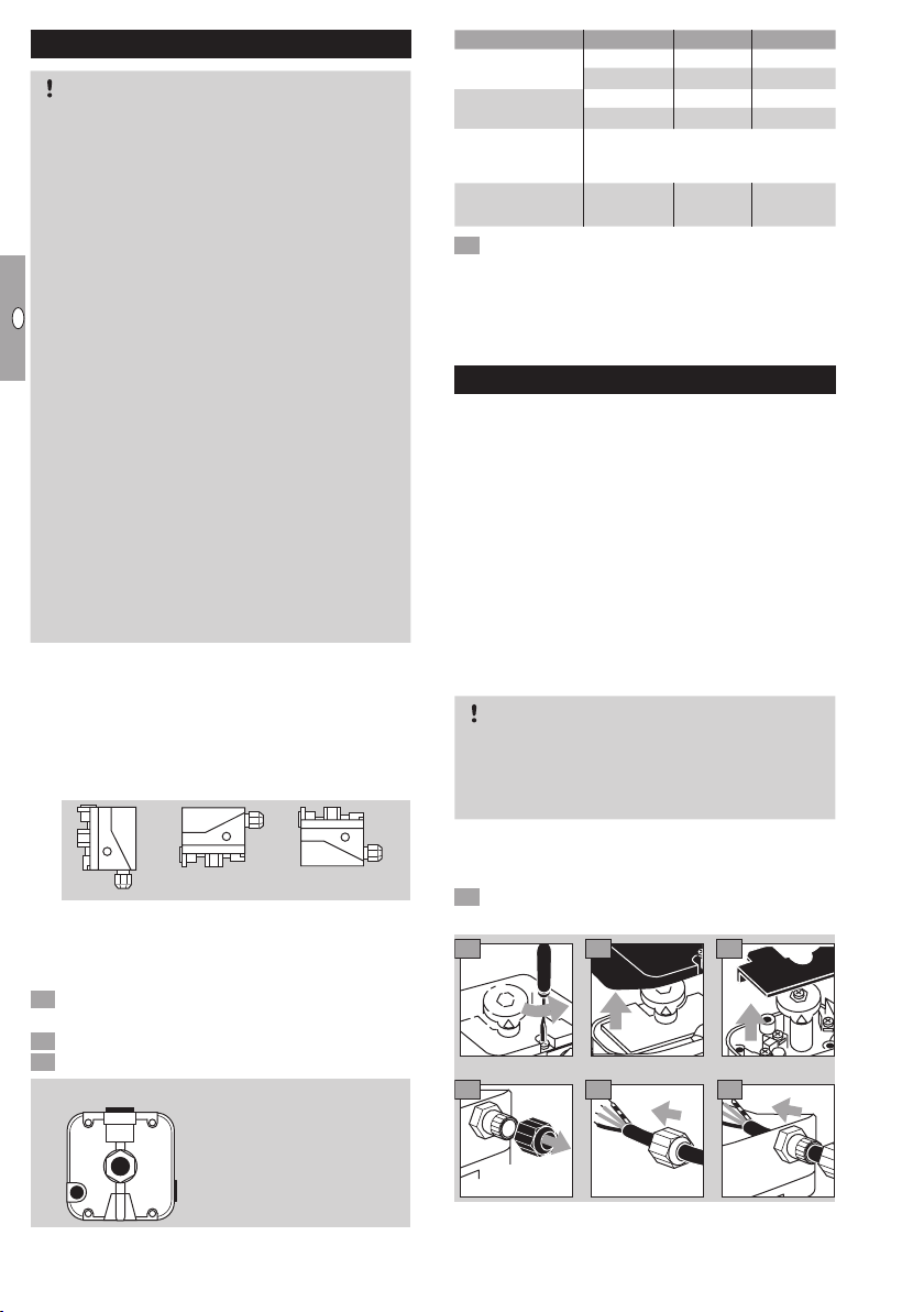
▷Installation position as required, preferably with
vertical diaphragm. Then the switching pointpS
corresponds to the scale valueSK set on the
hand wheel. In other installation positions, the
switching pointpSwill change and no longer
correspond to the scale valueSK set on the
hand wheel. Check the switching point.
ps=SK ps=SK+ 0,18 mbar ps=SK-0,18 mbar
▷
The DG must not be in contact with masonry.
Minimum clearance 20mm.
▷Ensure that there is sufficient installation space.
▷Ensure unobstructed view of the hand wheel.
1 Disconnect the system from the electrical power
supply.
2 Shut off the gas supply.
3 Ensure that the pipeline is clean.
2
1
3
4
1 and 2
Positive pressure
(Rp ¼)
3 and 4
Negative pressure
(Rp 1
/8)
Connect Seal Free
Positive pres-
sure DG..U
1 2 3 or 4
2 1 3 or 4
Negative pres-
sure DG..U
3 4 1 or 2
4 3 1 or 2
Differential pres-
sure DG..U
1or 2for higher absolute pressure.
3or 4for lower absolute pressure.
Seal the ports that are not in use.
Positive pressure
DG..B 1– –
4 If the electrical contacts in the DG could be soiled
by dirt particles in the surrounding air or in the
medium, use a filter pad (Order No.74946199)
at port3/4. On IP65 units, the filter pad is fitted
as standard, see type label.
Wiring
▷If the DG..G has switched a voltage > 24 V and a
current > 0.1 A at cos φ = 1 or > 0.05 A at cos φ =
0.6 once, the gold plating on the contacts will have
been burnt through. It can then only be operated at
this power rating or higher power rating.
▷
Pressure switch DG can be used in Zone1
(21) and2 (22) hazardous areas if an isolating
amplifier is installed upstream in the safe area
as “Ex-i”equipment pursuant to EN60079-11
(VDE0170-7):2007.
▷
DG as “simple electrical equipment” pursuant to
EN60079-11:2007 corresponds to the Tempera-
ture classT6, GroupII. The internal inductance/
capacitance is Lo= 0.2μH/Co= 8pF.
CAUTION
Please observe the following to ensure that the DG
is not damaged during operation:
– Note the switching capacity, see page 3
(Technical data).
▷
In the case of low switching capacities, such as
24V, 8mA, for example, we recommend using an
RCmodule (22Ω, 1μF) in air containing silicone or oil.
1 Disconnect the system from the electrical power
supply.
M16 x 1,5:
ø 4–10 mm
3 42
5 6 7
▷
Contacts 3and 2close when subject to increas-
ing pressure. Contacts 1and 3close when sub-
ject to falling pressure.
GB-3
D
GB
F
NL
I
E
NO
2
NC
1
COM
3
L1
COM
3
NC
1
NO
2
Adjustment
▷
The switching point is adjustable via hand wheel.
1 Disconnect the system from the electrical power
supply.
2 Detach the housing cover, see page3 (Tech-
nical data).
3 Connect an ohmmeter.
NO
2
NC
1
COM
3
COM
3
NC
1
NO
2
0
1 cm = 1 mbar
4 Set the switching point using the hand wheel.
5 Connect a pressure gauge.
NO
2
NC
1
COM
3
COM
3
NC
1
NO
2
0
1 cm = 1 mbar
6 Apply pressure. In doing so, monitor the ohm-
meter and the pressure gauge.
Type
Adjusting
range*
[mbar]
Switching
differential**
[mbar]
Max. inlet
pressure
pmax [mbar]
DG 6 0.4 – 6 0.2 – 0.3 100
DG 10 1 – 10 0.25 – 0.4 500
DG 30 2.5 – 30 0.35 – 0.9 500
DG 50 2.5 – 50 0.8 – 1.5 500
DG 150 30 – 150 3 – 5 600
DG 400 50 – 400 5 – 15 600
DG 500 100 – 500 8 – 17 600
* Adjusting tolerance = ± 15% of the scale value.
** Mean switching differential at min. and max. setting.
▷
Deviation from the switching point during test-
ing pursuant to EN1854 Gas and air pressure
switches: ±15%. For DG6: EN1854 Air pressure
switches: ± 15% or ±0.1mbar.
▷
If the DG does not trip at the desired switching
point, correct the adjusting range using the hand
wheel. Relieve the pressure and repeat the process.
Tightness test
1 Shut off the downstream gas pipeline close to
the valve.
2 Open the valve and the gas supply.
▷Check all used ports for tightness.
N2
900 mbar
max. 2 bar
< 15 min
3 4
Maintenance
In order to ensure smooth operation: check the tight-
ness and function of the DG every year, or every six
months if operated with biogas.
▷A function check can be carried out in case of
decreasing pressure control e.g. with the PIA.
▷After carrying out the maintenance work, check
for tightness, see page3 (Tightness test).
Technical data
Gas type: natural gas, town gas, LPG (gaseous),
flue gas, biogas (max. 0.1%-by-vol. H2S) and air.
Max. inlet pressure pmax = withstand pressure,
see page 3 (Adjustment). Max. test pressure
for testing the entire system: temporarily <15min-
utes 2bar.
Switching capacity:
U I (cos φ = 1) I (cos φ = 0,6)
DG
24 – 250 V AC
0.05 – 5 A 0.05 – 1 A
DG..G 5 – 250 V AC 0.01 – 5 A 0.01 – 1 A
5 – 48 V DC 0.01 – 1 A
Maximum medium and ambient temperatures:
-20 to +80°C.
Long-term use in the upper ambient temperature
range accelerates the ageing of the elastomer ma-
terials and reduces the service life (please contact
manufacturer).
Storage temperature: -20 to +40°C.
Diaphragm pressure switch, silicone-free.
Diaphragm: NBR.
Housing: glass fibre reinforced PBT plastic with
low gas release.
Lower housing section: AlSi 12.
Enclosure: IP54 or IP65.
Safety class: 1.
Line diameter: 0.5 to 1.8 mm (AWG 24 to AWG13).
Line entrance: M16 x 1.5, clamping range: diam-
eters of 4 to 10mm.
Electrical connection type: screw terminals, max.
torque: 250 Ncm.
Weight: 270to320g.
Designed lifetime
This information on the designed lifetime is based on
using the product in accordance with these operat-
ing instructions. Once the designed lifetime has been
reached, safety-relevant products must be replaced.
D
GB
F
NL
I
E
Designed lifetime (based on date of manufacture) in
accordance with EN 13611, EN 1854 for pressure
switches:
Medium Designed lifetime
Switching cycles Time [years]
Gas 50,000 10
Air 250,000 10
You can find further explanations in the applicable
rules and regulations and on the afecor website
(www.afecor.org).
This procedure applies to heating systems. For thermo-
processing equipment, observe local regulations.
Accessories
See Technical Information DG (D, GB, F) –
www.docuthek.com
Logistics
Transport
Protect the unit from external forces (blows, shocks,
vibration). On receipt of the product, check that the
delivery is complete, see page 1 (Part designa-
tions). Report any transport damage immediately.
Storage
Store the product in a dry and clean place.
Storage temperature: see page 3 (Technical data).
Storage time: 6 months before using for the first
time. If stored for longer than this, the overall service
life will be reduced by the corresponding amount of
extra storage time.
Packaging
The packaging material is to be disposed of in ac-
cordance with local regulations.
Disposal
Components are to be disposed of separately in
accordance with local regulations.
Certification
Declaration of conformity
We, the manufacturer, hereby declare that the product
DG, marked with product ID No. CE-0085AP0467,
complies with the requirements of the listed Direc-
tives and Standards.
Directives: 2009/142/EC, 2006/95/EC
Standards: EN 13611, EN 1854
The relevant product corresponds to the type tested
by the notified body 0085. The production is subject
to the surveillance procedure pursuant to Directive
2009/142/EC Annex II paragraph 3 and to the Quality
System pursuant to DIN EN ISO 9001:2008.
Elster GmbH
Scan of the Declaration of conformity (D, GB) – see
www.docuthek.com
SIL, PL
The pressure switches are suitable for single-channel
systems (HFT = 0) up to SIL 2/PL d, and up to SIL3/
PL e when two redundant pressure switches are
installed in a double-channel architecture (HFT = 1),
provided that the complete system complies with the
requirements of EN 61508/ISO 13849. The safety
function value which is actually achieved is derived
by taking all components into account (sensor – logic
– actuator). For this, the demand rate and structural
measures to avoid/detect nonconformity are to be
observed (e.g. redundancy, diversity, monitoring).
Characteristic values for SIL/PL: HFT = 0 (1de-
vice), HFT = 1 (2 devices), SFF > 90, DC = 0,
type A/category B, 1, 2, 3, 4, high demand mode,
CCF>65, ß ≥ 2.
PFHD= λD= x nop
=
1
MTTF
d
0,1
B
10d
U I B10d value
24 V DC 10 mA 6,689,477
230 V AC 4 mA
24 V DC 70 mA 4,414,062
230 V AC 20 mA
230 V AC 2 A 974,800
RoHS compliant, Eurasian Customs Union,
AGA approved
AGA

This manual suits for next models

2

Other Krom Schroder Switch manuals

Krom Schroder CPS 1000 User manual

Krom Schroder

Krom Schroder CPS 1000 User manual

Krom Schroder DL H Series User manual

Krom Schroder

Krom Schroder DL H Series User manual

Krom Schroder DL H Series User manual

Krom Schroder

Krom Schroder DL H Series User manual

Krom Schroder DG**H series User manual

Krom Schroder

Krom Schroder DG**H series User manual

Krom Schroder DL K Series User manual

Krom Schroder

Krom Schroder DL K Series User manual

Krom Schroder DL A Series User manual

Krom Schroder

Krom Schroder DL A Series User manual

Krom Schroder DL 1,5A User manual

Krom Schroder

Krom Schroder DL 1,5A User manual

Krom Schroder DG..S Series User manual

Krom Schroder

Krom Schroder DG..S Series User manual

Krom Schroder DG**H series User manual

Krom Schroder

Krom Schroder DG**H series User manual

Popular Switch manuals by other brands

Voodoo Lab GCX owner's manual

Voodoo Lab

Voodoo Lab GCX owner's manual

Fracarro Smart Switchline SWI85 STPLUS Series operating instructions

Fracarro

Fracarro Smart Switchline SWI85 STPLUS Series operating instructions

Endress+Hauser Liquiphant S FTL70 operating instructions

Endress+Hauser

Endress+Hauser Liquiphant S FTL70 operating instructions

Eaton COOPER POWER SERIES Installation and adjustment instructions

Eaton

Eaton COOPER POWER SERIES Installation and adjustment instructions

LEGRAND 5 745 03 user guide

LEGRAND

LEGRAND 5 745 03 user guide

Dataprobe 4P-MAS quick start guide

Dataprobe

Dataprobe 4P-MAS quick start guide

milleteknik 4p M user manual

milleteknik

milleteknik 4p M user manual

Nortel 2300 Series Reference

Nortel

Nortel 2300 Series Reference

Indu-Sol PROmesh U16 Quick start user guide

Indu-Sol

Indu-Sol PROmesh U16 Quick start user guide

Ultra Products ULT31106 Specifications

Ultra Products

Ultra Products ULT31106 Specifications

HP aruba 9300-32D Series Installation and getting started guide

HP

HP aruba 9300-32D Series Installation and getting started guide

THOMSON TTN-BAS-0808CP installation manual

THOMSON

THOMSON TTN-BAS-0808CP installation manual

Cisco IE-3000-8TC Software configuration guide

Cisco

Cisco IE-3000-8TC Software configuration guide

Alcatel-Lucent OmniSwitch 6855-24 Hardware user's guide

Alcatel-Lucent

Alcatel-Lucent OmniSwitch 6855-24 Hardware user's guide

Siemens 5WG1 523-1AB03 Technical product information

Siemens

Siemens 5WG1 523-1AB03 Technical product information

Airlink101 AKVM-2UDA Quick installation guide

Airlink101

Airlink101 AKVM-2UDA Quick installation guide

Avaya ERS 3500 Quick setup guide

Avaya

Avaya ERS 3500 Quick setup guide

NETGEAR M4500 Series Hardware installation guide

NETGEAR

NETGEAR M4500 Series Hardware installation guide

manuals.online logo
manuals.online logoBrands
  • About & Mission
  • Contact us
  • Privacy Policy
  • Terms and Conditions

Copyright 2025 Manuals.Online. All Rights Reserved.