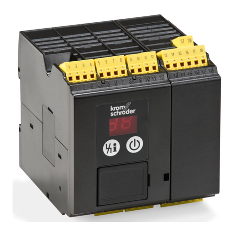
Kromschroeder MPT 700 User manual

Impulse system
MPT 700
Manual 6.2.2.2 Edition 1.03 GB

MPT 700
2
1Introduction ....................................................................................... 4
1.1 Version and model ............................................................................................. 5
1.2 CE Mark............................................................................................................. 7
2Operation........................................................................................... 8
2.1 Controls ............................................................................................................. 8
2.1.1 Front panel................................................................................................... 8
2.1.2 Parameter display ........................................................................................ 9
2.1.3 Group indicator ............................................................................................ 9
2.1.4 Setting source indicators.............................................................................. 9
2.1.5 Malfunction indicator .................................................................................. 10
2.1.6 Switching output indicators ........................................................................ 10
2.1.7 Keypad....................................................................................................... 10
2.2 Operation of the unit ........................................................................................ 11
2.2.1 General ...................................................................................................... 11
2.2.2 Parameters 0...4: normal operation............................................................ 11
2.2.3 Parameter entry - general .......................................................................... 11
3Modes of operation......................................................................... 13
3.1 Mode of operation 1 - heating with fixed pulse width ....................................... 13
3.2 Mode of operation 2 - heating/cooling with fixed pulse width ........................... 14
3.3 Mode of operation 3 - heating with variable pulse width and spacing .............. 16
3.4 Mode of operation 4 - heating/cooling with variable pulse width and spacing.. 18
3.5 Mode of operation 5 - heating with fixed pulse width and separate air and
gas valve control.............................................................................................. 21
3.6 Mode of operation 6 - heating/cooling with fixed pulse width and separate air
and gas valve control ....................................................................................... 23
3.7 Mode of Operation 7- heating with variable pulse width and spacing and
separate air and gas valve control ................................................................... 25
3.8 Mode of Operation 8 - heating/cooling with variable pulse width and spacing
and separate air and gas valve control ............................................................ 28
4Adjustable parameters 10...87 ....................................................... 31
4.1 Parameter 10 - setting source.......................................................................... 31
4.2 Parameter 11 - mode of operation ................................................................... 32
4.3 Parameter 12, 13 - equipment address............................................................ 32
4.4 Parameter 14 - setting indicator....................................................................... 32
4.5 Parameters 15, 16 - number of outputs ........................................................... 32
4.6 Parameter 18 - MPT mode .............................................................................. 33
4.7 Parameter 19 - keyboard repetition rate .......................................................... 33
4.8 Parameters 20...27 - ignition timing, channels 1...8 ......................................... 33
4.9 Parameter 28, 29 - setting control factor.......................................................... 35
4.10 Parameter 30, 31 - heating/cooling limit........................................................ 35
4.11 Parameter 32, 33 - heating/cooling dead zone ............................................. 35
4.12 Parameter 34, 35 - continuous pulse ............................................................ 37
4.13 Parameter 36, 37 - control rate (three-point step controller) ......................... 37
4.14 Parameter 38, 39 - fixed setting.................................................................... 38
4.15 Parameters 40...47 / 60...67 - pulse widths................................................... 38
4.16 Parameters 48, 54, 68, 74 - minimum on time .............................................. 39
4.17 Parameters 49, 55, 69, 75 - minimum off time .............................................. 39
MPT 700
3
4.18 Parameters 50...53 / 56...59 / 70...73 / 76...79 - delays ................................ 39
4.19 Parameter 87 - equipment code.................................................................... 40
5Appendix.......................................................................................... 41
5.1 Installation ........................................................................................................ 41
5.1.1 Proper use.................................................................................................. 41
5.1.2 Installation notes and safety precautions ................................................... 41
5.1.3 General ...................................................................................................... 42
5.1.4 Ground connection ..................................................................................... 43
5.1.5 Power supply connections.......................................................................... 43
5.1.6 Binary control inputs................................................................................... 44
5.1.7 mA control inputs........................................................................................ 44
5.1.8 Switching outputs ....................................................................................... 45
5.2 Connection Plans ............................................................................................. 46
5.2.1 Main board ................................................................................................. 46
5.2.2 Power supply board.................................................................................... 47
5.2.3 Jumpers (on main board) ........................................................................... 48
5.2.4 Fuses (on power supply board).................................................................. 48
5.2.5 Block diagram (overview) ........................................................................... 49
5.2.6 Terminal plan (CN1) ................................................................................... 50
5.3 Brief instructions............................................................................................... 51
5.3.1 Modes of operation..................................................................................... 51
5.3.2 Parameter 10 - setting source .................................................................... 51
5.3.3 Parameters 0...99....................................................................................... 52
5.4 Test and service instructions............................................................................ 53
5.4.1 Parameter 5: test mA control input/phase .................................................. 54
5.4.2 Parameter 6: test of binary control inputs................................................... 54
5.4.3 Parameter 7: test of switching outputs ....................................................... 55
5.4.4 Parameter 8: error parameter number ....................................................... 55
5.4.5 Parameter 9: error code ............................................................................. 56
5.4.6 Parameters 90...98: event counters ........................................................... 57
5.4.7 Parameter 99: display test.......................................................................... 57
5.4.8 Cold start.................................................................................................... 57
5.4.9 Connections ............................................................................................... 57
5.5 Technical specifications ................................................................................... 58

MPT 700
4
1 Introduction
Dear Customer,
Thank you very much for the interest which you have shown in our products.
You have opted for our new generation of equipment in accordance with CE
requirements, the MPT 700 Rev.C burner cycle control unit, which is designed for
controlling up to eight burners in one or two groups in any of eight modes of
operation.
This unit was developed on the basis of our experience with the preceding model,
the MPT 608/618, and the wishes of our customers.
The unit incorporates the following improvements:
• 1...8 burner outputs, irrespective of the hardware configuration
• separate connections for 3-point step control, mA control, heating/cooling and
malfunction signals ⇒no jumper settings required
• power supply unit designed for 95...240VAC input and low heat emission
• safety-oriented logic for heating/cooling and malfunction outputs (heating/no
malfunction ⇒output active)
• switching outputs positive (+12...24VDC) and common ground
• two mA inputs ⇒no external pulse relay required
• checking the measured values of the analog input channels on accuracy (mA-
Input)
Please read this manual, especially the installation and commissioning instructions
(section 5.1), carefully and follow the instructions. Otherwise, we will be unable to
assume any warranty for damage to the unit.
If you have any further questions, please do not hesitate to contact your supplier,
who will be pleased to help you.
G. Kromschröder AG
Strotheweg 1
D-49504 Lotte (Büren)
Germany
Tel.: +49/0-541-1214-0
Fax.: +49/0-541-1214-370

MPT 700
5
1.1 Version and model
• MPT 700 with two burner groups per unit:
- current version: Type 2 / program version 6.0
- 8 modes of operation
- two parameter sets, switchable
- two mA inputs
- one three-point step input for multiplex operation
The MPT 700 can be adjusted to behave in the same way as a single-group unit
by setting the number of outputs for group 1 to 8 burners (parameter 15) and for
group 2 to 0 burners (parameter 16) and the setting indicator to group 1
(parameter 14).
To check the version, proceed as follows (see also section 2):
• Set the parameter number to 0 using the right section of the keypad.
• Press the top button on the right (+) for 5 sec.
⇒the type and the program version number will then appear on the display.
Example:
display: 02.60 ⇒Type 2 / program version 6.0
MPT 700:
• new model with switched +Vcc (+12...24VDC) and common ground (GND)

MPT 700
6
For downward compatibility reasons, it is still possible to operate the MPT 700 in
the 608 software mode (see section 4.6)
For intention to replace the MPT 608 as well as the MPT 618 with the MPT 700,
it's necessaray to make some changes in the wireing of the installation:
• Wireing of the electrical connections to a different mating plug
• In mode 108 / 128 it's necessary to link a grounding conductor as like shown in
the terminal plan (see Section 5.2.6). In mode 108 the burner output 8 is used
for 'Heating / Cooling' with the Single Group Unit and burner output 7 and 8
with the Dual Group Unit.
take into consideration that the switching logic for the outputs 'Heating Cooling
1', Heating Cooling 2' and 'Out /Error' in the ESV 128 is different to the ESV
148. Therefore the connected relais may have another switching reaction.
The differences are shown in the following table:
Type Out H/K 1 Out H/K 2 Out /Error
MPT 608 switched switched switched
MPT 700 not switched not switched not switched
Normally for the same function other switching contacts must be used. (the
contacts has to be changed instead of a normally closed contact to a normally
open contact and the other way round dependent of plant spezific facts)
• Basicly the instructions of installation in the appendix (section 5) for the
MPT 700 device must be used.
Before commissioning the unit, always check the model (nameplate), the version
(follow the instructions above) and the parameters set. Otherwise, the unit or the
equipment connected may be damaged or destroyed.

MPT 700
7
1.2 CE Mark
CE marks are applied in accordance with a Directive of the Council of the
European Communities of 29 April 1991 on the approximation of the laws of the
Member States relating to the mutual recognition of conformity. Since the 01
Januar 1997 all temporary regulations had been dropped, so the new "EG
concurring standartisations" are valid.
The MPT 700 burner cycle control unit described in this manual is supplied
complete with a CE mark guaranteeing:
• compliance with the electromagnetic compatibility directive
• compliance with the low-voltage directive

MPT 700
8
2 Operation
2.1 Controls
2.1.1 Front panel
group indicator
4-digit parameter display
setting source indicators
malfunction indicator
2-digit parameter number display
keypad
switching output indicators

MPT 700
9
2.1.2 Parameter display
• In operation, the parameter display indicates the current setting.
heating ⇒0%...+100%
heating/cooling ⇒-100%...+100%
• During parameter input, the value of the parameter is indicated in the unit which
is valid at the time.
• Error codes and service parameters are only indicated for troubleshooting and
inspection purposes.
2.1.3 Group indicator
• During normal operation, this indicator indicates the group to which the setting
which is displayed applies.
1 bar ⇒group 1
2 bars ⇒group 2
2.1.4 Setting source indicators
• These indicators show the setting source which is currently active.
MC ⇒MPT 700: no function
mA ⇒control by analogue 0/4...20mA signal
⇒three-point step controller
⇒manual control
• If a green LED flashes, no valid setting is available at the input concerned (this
only applies to 'MC' and 'mA' (0/4...20mA)).
MC ⇒MPT 700: no function
mA ⇒mA value < 2mA or > 20,7mA (in 4...20mA operation)
mA value > 20,7 mA (in 0...20mA operation)

MPT 700
10
2.1.5 Malfunction indicator
⇒unit malfunction
• If the unit detects a malfunction during its cyclical self-test, the red LED is lit, the
4 green LEDs all flash and the binary "malfunction" output signal is activated.
Troubleshooting is described in section 5.4 below.
In case of the fault 'mA' is happened (source indicator 02), the green LED is lit
and the "malfunction" indicator is gone into steady light. Simultaneous the
output "malfunction" (Out /Error) is set.
2.1.6 Switching output indicators
• These LEDs indicate which outputs are being addressed at any time.
• As the indicators only indicate that the output drivers are being addressed, it is
not possible to use them for detecting a faulty output driver or a wire breakage.
2.1.7 Keypad
• left buttons:
selection of setting source
selection of parameters
selection of service displays
• right buttons:
changing the setting in manual operation
changing parameter values
All the functions of the unit, including setting input, parameter entry and
troubleshooting, must be implemented manually.

MPT 700
11
2.2 Operation of the unit
2.2.1 General
All the functions of the unit, including parameter changes, the selection of a setting
source/calling up the setting and troubleshooting, can be initiated manually using
the keypad.
2.2.2 Parameters 0...4: normal operation
• For NORMAL OPERATION, the parameter number display must be set to a
value between 0 and 4.
• Changes in the signal source (e.g. 2 ⇒3) are only implemented after about 5
sec. This delay prevents uncontrolled changes in parameter selection.
Parameter
No.
Meaning
0 all outputs are reset
1 MPT 700: no function
2 setting from controller (continuous / three-point step)
3 manual setting for group 1
4 manual setting for group 2
2.2.3 Parameter entry - general
• In modes of operation 1 to 8, two parameter sets are available for pulse widths,
min. on time, min. off time and ignition timing delays.
• The unit is switched over between parameter sets externally by binary input 2.
input 2 inactive ⇒parameter set 1 valid
input 2 active ⇒parameter set 2 valid
parameter set 1: parameters 40...59
parameter set 2: parameters 60...79

MPT 700
12
2.2.3.1 Selection of parameters
• All the parameters can be checked while the unit is in service without any effect
on operation.
• To check a parameter, select the parameter required using the left half of the
keypad.
⇒The value of the parameter will then appear on the four-digit display in the
valid unit.
2.2.3.2 Changing parameters
• It is only possible to change parameters if the current equipment code is 0 or
the correct equipment code is entered (see parameter 87).
• Select the parameter which you wish to change using the keypad.
• The current value of the parameter will then appear on the four-digit display.
• You can increase or reduce the value using the right half of the keypad.
• If you select another parameter, the value which you have entered will be stored
in interim memory, but will not yet be effective.
• Changed parameters only become effective when the unit is switched back to
NORMAL OPERATION (parameters 0 to 4).

MPT 700
13
3 Modes of operation
3.1 Mode of operation 1 - heating with fixed pulse width
• The pulse width is set to a fixed value for each channel.
• If the setting is changed, the pulse spacing is changed.
• Max. pulse frequency = 1 / (pulse width + minimum off time)
• Even before the unit changes from pulse operation to a continuous pulse, the
minimum off time never falls below the set parameter value.
Adjustable parameters in mode of operation 1:
Parameter
(G1/G2)
Designation Range Section Remarks
10 setting source 0...5 4.1
11 mode of operation 1 4.2
12/13 equipment address 1...32 4.3 not relevant for operation
14 setting indicator 0...2 4.4
15/16 number of outputs 0...8 4.5
18 MPT mode 108/128 4.6
19 keyboard repetition rate 1...32 4.7
20...27 ZZP1...ZZP8 0/1...255 0
34/35 continuous pulse 0/50...100% 4.12
0% ⇔no continuous pulse
36/37 control rate 1...180s 4.13 only for TPS unit
38/39 fixed setting 0/1...100% 4.14
0% ⇔no fixed setting
40...47 pulse widths 50ms...160s 4.15 parameter set 1
49/55 min. off time 50ms...160s 4.17 parameter set 1
60...67 pulse widths 50ms...160s 4.15 parameter set 2
69/75 min. off time 50ms...160s 4.17 parameter set 2
87 equipment code 0/1...255 4.19
0 ⇔no equipment code
ZZP: ignition timing
TPS: three-point step controller

MPT 700
14
3.2 Mode of operation 2 - heating/cooling with fixed pulse width
• The pulse width is set to a fixed value for each channel.
• If the setting is changed, the pulse spacing is changed.
• Max. pulse frequency = 1 / (pulse width + minimum off time)
• Even before the unit changes from pulse operation to a continuous pulse, the
minimum off time never falls below the set parameter value.
• Setting source: heating/cooling limit and heating/cooling dead zone adjustable
(see diagram in section 4.11)
• For burner and valve control a maximum of 8 outputs is available in 128 mode
(a maximum of 6 in 108 mode).
• If required, a relay for external switchover between heating and cooling can be
controlled by the heating/cooling 1 and 2 outputs (mode 128) or outputs 7 and 8
(mode 108).
⇒output inactive: cooling
output active: heating

MPT 700
15
Adjustable parameters in mode of operation 2:
Parameter
(G1/G2)
Designation Range Section Remarks
10 setting source 0...5 4.1
11 mode of operation 2 4.2
12/13 equipment address 1...32 4.3 not relevant for operation
14 setting indicator 0...2 4.4
15/16 number of outputs 0...8 4.5
18 MPT mode 108/128 4.6
19 keyboard repetition rate 1...32 4.7
20...27 ZZP1...ZZP8 0/1...255 0
30/31 heating/cooling limit 10...90% 0
32/33 heating/cooling dead zone 0...50% 4.11
34/35 continuous pulse 0/50...100% 4.12
0% ⇔no continuous pulse
36/37 control rate 1...180s 4.13 only for TPS unit
38/39 fixed setting 0/1...100% 4.14
0% ⇔no fixed setting
40...47 pulse widths 50ms...160s 4.15 parameter set 1
49/55 min. off time 50ms...160s 4.17 parameter set 1
60...67 pulse widths 50ms...160s 4.15 parameter set 2
69/75 min. off time 50ms...160s 4.17 parameter set 2
87 equipment code 0/1...255 4.19
0 ⇔no equipment code
ZZP: ignition timing
TPS: three-point step controller

MPT 700
16
3.3 Mode of operation 3 - heating with variable pulse width and
spacing
• In this mode of operation, no fixed pulse widths are defined.
• The pulse width or the pulse spacing changes as a function of the setting.
• Max. pulse frequency = 1 / (min. on time + min. off time)
• The maximum pulse frequency is reached at a setting corresponding to the
value entered for parameter 28 and 29 ('XX' in diagram).
• Even before the unit changes from pulse operation to a continuous pulse, the
minimum off time never falls below the set parameter value.
Pulse diagram:
1. setting 1%
⇒min. on time / max. off time
2. setting 1%...XX%
⇒min. on time / off time is reduced
3. setting XX%
⇒min. on time / min. off time
maximum pulse frequency
4. setting XX%...99%
⇒min. off time / on time is increased
5. setting 100%
⇒continuous pulse
XX% ⇒value in parameter 28 (10...90%)

MPT 700
17
Adjustable parameters in mode of operation 3:
Parameter
(G1/G2)
Designation Range Section Remarks
10 setting source 0...5 4.1
11 mode of operation 3 4.2
12/13 equipment address 1...32 4.3 not relevant for operation
14 setting indicator 0...2 4.4
15/16 number of outputs 0...8 4.5
18 MPT mode 108/128 4.6
19 keyboard repetition rate 1...32 4.7
20...27 ZZP1...ZZP8 0/1...255 0
28/29 setting control factor 10...90% 4.9
34/35 continuous pulse 0/50...100% 4.12
0% ⇔no continuous pulse
36/37 control rate 1...180s 4.13 only for TPS unit
38/39 fixed setting 0/1...100% 4.14
0% ⇔no fixed setting
48/54 min. on time 50ms...160s 4.15 parameter set 1
49/55 min. off time 50ms...160s 4.17 parameter set 1
68/74 min. on time 50ms...160s 4.15 parameter set 2
69/75 min. off time 50ms...160s 4.17 parameter set 2
87 equipment code 0/1...255 4.19
0 ⇔no equipment code
ZZP: ignition timing
TPS: three-point step controller

MPT 700
18
3.4 Mode of operation 4 - heating/cooling with variable pulse
width and spacing
• In this mode of operation, no fixed pulse widths are defined.
• The pulse width or the pulse spacing changes as a function of the setting.
• Max. pulse frequency = 1 / (min. on time + min. off time)
• The maximum pulse frequency is reached at a setting corresponding to the
value entered for parameter 28 and 29 ('XX' in diagram).
• Even before the unit changes from pulse operation to a continuous pulse, the
minimum off time never falls below the set parameter value.
• Setting source: heating/cooling limit and heating/cooling dead zone adjustable
(see diagram in section 4.11)
• For burner and valve control a maximum of 8 outputs are available in 128 mode
(a maximum of 6 in 108 mode).
• If required, a relay for external switchover between heating and cooling can be
controlled by the heating/cooling 1 and 2 outputs (mode 128) or outputs 7 and 8
(mode 108).
⇒output inactive: cooling
output active: heating

MPT 700
19
Pulse diagram:
1. setting 1%
⇒min. on time / max. off time
2. setting 1%...XX%
⇒min. on time / off time is reduced
3. setting XX%
⇒min. on time / min. off time
maximum pulse frequency
4. setting XX%...99%
⇒min. off time / on time is increased
5. setting 100%
⇒continuous pulse
XX% ⇒value in parameter 28 (10...90%)

MPT 700
20
Adjustable parameters in mode of operation 4:
Parameter
(G1/G2)
Designation Range Section Remarks
10 setting source 0...5 4.1
11 mode of operation 4 4.2
12/13 equipment address 1...32 4.3 not relevant for operation
14 setting indicator 0...2 4.4
15/16 Number of outputs 0...8 4.5
18 MPT mode 108/128 4.6
19 keyboard repetition rate 1...32 4.7
20...27 ZZP1...ZZP8 0/1...255 0
28/29 setting control factor 10...90% 4.9
30/31 heating/cooling limit 10...90% 0
32/33 heating/cooling dead zone 0...50% 4.11
34/35 continuous pulse 0/50...100% 4.12
0% ⇔no continuous pulse
36/37 control rate 1...180s 4.13 only for TPS control
38/39 fixed setting 0/1...100% 4.14
optional 0% ⇔no fixed setting
48/54 min. on time 50ms...160s 4.16 parameter set 1
49/55 min. off time 50ms...160s 4.17 parameter set 1
68/74 min. on time 50ms...160s 4.16 parameter set 2
69/75 min. off time 50ms...160s 4.17 parameter set 2
87 equipment code 0/1...255 4.19
0 ⇔no equipment code
ZZP: ignition timing
TPS: three-point step controller
Table of contents
Other Kromschroeder Control Unit manuals

Kromschroeder
Kromschroeder IFD 258 Manual

Kromschroeder
Kromschroeder VAN Series User manual

Kromschroeder
Kromschroeder VR Series User manual

Kromschroeder
Kromschroeder VAS 1-3 User manual

Kromschroeder
Kromschroeder IFD 244 User manual

Kromschroeder
Kromschroeder VG 6-15/10 User manual

Kromschroeder
Kromschroeder BCU 570 User manual

Kromschroeder
Kromschroeder BCU 56 Series User manual

Kromschroeder
Kromschroeder BCM 400 B1 Series User manual