4Mounting
4.1General instructions
The note of the following general safety instructions:
lDismount the lock fitting only in unpressurized condition
lUse only suitable graphite gasket rings.Make sure that the
graphite gasket rings are not damage.Damaged rings are
no longer tight.If you are not sure,use new rings.
lOnly use approved hexagon screws DIN 912 M6x25 of
A4-70 according to AD leaflet W2.The corresponding
spring rings B6must be made of A4according to DIN 7980.
lGrease the thread and the support of the terminal screws
with a suitable lubricant.The lubricant must be suitable for
material combination 316L/316Land for a temperature
range of -50 …+250°C(-58 …+482°F)e.g.Varybond
type NSS-16/7.The threads are already supplied with a
lubricant.
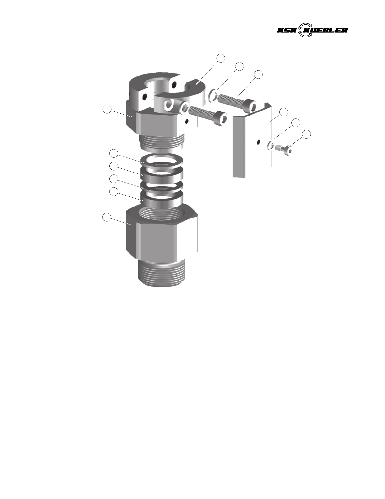
4.2Mounting sequence
The lock fitting is already premounted.
The numbers in brackets refer to the following illustration.
1Loosen the screw (6)and remove the locking bracket (4)
2Screw mounting boss (7)with a resistant seal ring into the
thread of the vessel and tighten the mounting boss (7)on
the hexagon (SW 41 or SW 60)
3Clean the connection tube of the sensor and the surfaces
of the clamp (1)as well as the pressure screw (11)
carefully and remove grease,oil and dirt.Insert the sensor
into the lock fitting.Slide the tube into the requested
position and hold it
4Make sure that the sensor is in the correct position (height).
The height adjustment of the sensor determines also the
switching point
5Tighten the pressure screw (11)with a torque 70 ±10 Nm
(51 ±7lbf ft)
6Continue to turn the pressure screw (11)clockwise until the
hexagon surfaces of the pressure screw (11)and the
mounting boss (7)correspond (max.1/6turn)
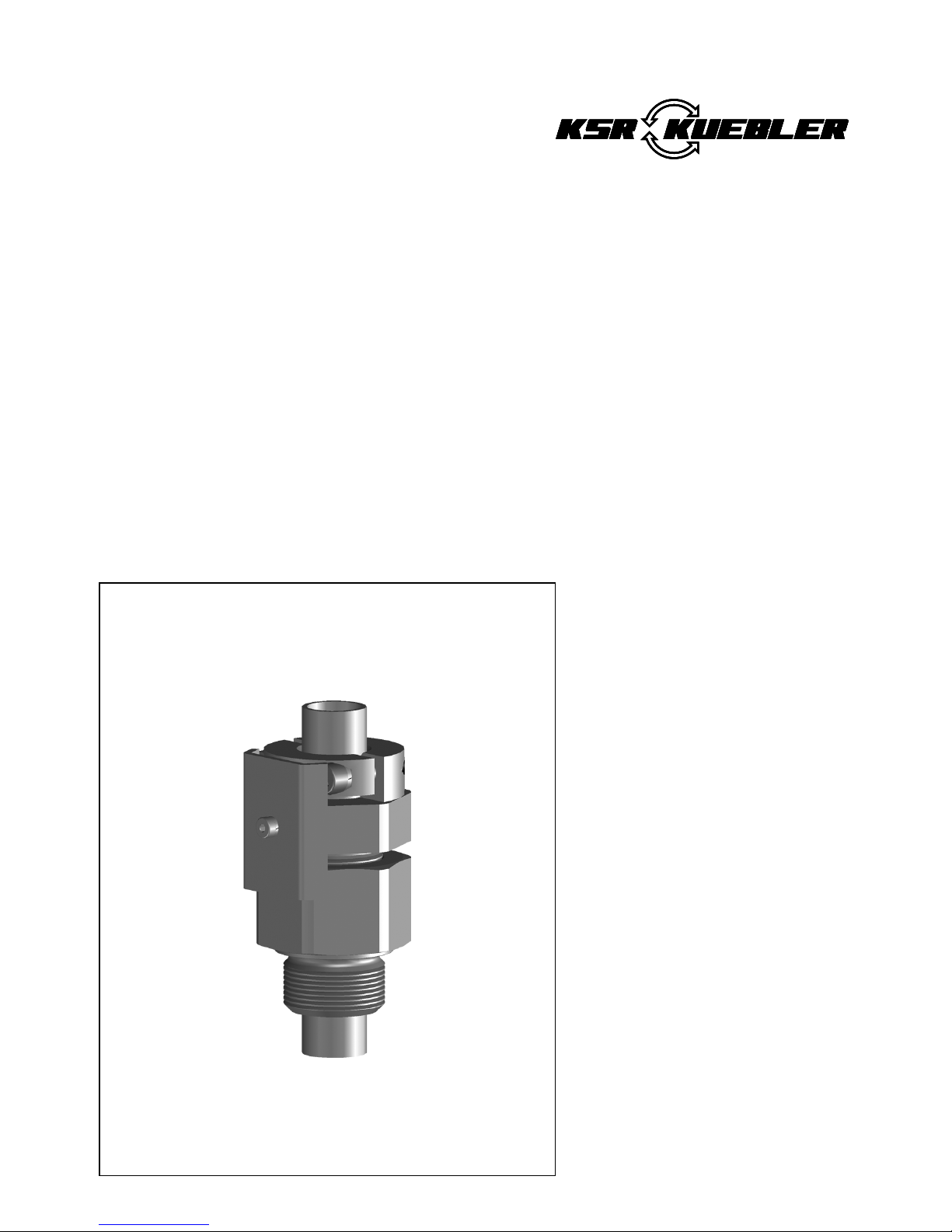
6Lock fitting ARV-TF633.2--pressure range:-1…16 bar
Mounting
32042-EN-060620