KTI KC-210TF-SXC User manual

-1-
1000BASE-T to 1000BASE-SX/LX
Media Converters
KC-210TF-SXC
KC-210TF-SXC-O
KC-210TF-LXC
KC-210TF-LXC-O
KC-210TF-LXC30-O
KC-210TF-LXC40
KC-210TF-LXC80
P/N: 750-0158-002
DOC.050727-KC210
Installation Guide

-2-
The information contained in this document is subject to change without
prior notice. Copyright (C) All Rights Reserved.
TRADEMARKS
Ethernet is a registered trademark of Xerox Corp.
FCC NOTICE
This device complies with Class A Part 15 the FCC Rules. Operation is
subject to the following two conditions: (1) This device may not cause
harmful interference, and (2) this device must accept any interference
received including the interference that may cause undesired operation.
CE NOTICE
Marking by the symbol indicates compliance of this equipment to
the EMC directive of the European Community. Such marking is indica-
tive that this equipment meets or exceeds the following technical stan-
dards:
EMC Class A
EN 50081-1/1992 : EN55022, EN61000-3-2, EN61000-3-3
EN 50082-1/1998 : EN61000-4-2, EN61000-4-3, EN61000-4-4, EN61000-4-5,
EN61000-4-6, EN61000-4-8, EN61000-4-11
Table of Contents
1. Introduction.........................................................3
1.1 Specifications ................................................................................ 4
2. Installation...........................................................5
2.1 Media Converters .......................................................................... 5
2.2 LED Indicators ............................................................................... 7
2.3 Applying Power .............................................................................. 8
2.4 Making Connection ........................................................................ 9

-3-
1. Introduction
The1000BASE-Tto1000BASE-SX/LX mediaconverterseriesprovides a media
conversion allowing Gigabit integration of fiber optic and copper (twisted-pair)
segments. It is used to extend the connection distance between two copper
Gigabit Ethernet devices via fiber optic cable transparently with no performance
degradation.
The converters also provide the following key features:
• Compliance with IEEE 802.3ab 1000BASE-T and IEEE 802.3z
1000BASE-SX, 1000BASE-LX standard
• Auto-negotiation function built in twisted-pair port that allows to
operate at optimal configuration connecting to an auto-negotiation
capable device
• Auto MDI/MDI-X crossover configuration and receiving polarity
error correction on twisted-pair interface
• Supporting low cost multimode fiber and single mode fiber cable
when long reach connection is needed
• Extending network span up to 10Km over duplex single mode fiber
cabling
• Setting switch to enable or disable auto-negotiation function of the
fiber port when connecting non-auto legacy 1000BASE-X device
• Full LED indicators for monitoring port and connection status
The converter series support the following configuration needs:
1000BASE-Tto 1000BASE-SX / LX
KC-210TF-SXC Copper to SX fiber 850nm SC
KC-210TF-LXC Copper to LX fiber 1310nm SC
KC-210TF-LXC30 Copper to LX fiber 1310nm SC 30km
KC-210TF-LXC40 Copper to LX fiber 1550nm SC 40km
KC-210TF-LXC80 Copper to LX fiber 1550nm SC 80km

-4-
1.1 Specifications
Twisted-PairInterface
Compliance IEEE802.3ab1000BASE-T
Connector Shielded RJ-45 jack
Pin assignments Auto-crossover for MDI and MDI-X
Data speed 1000Mbps
Duplex mode Auto-negotiation for half-duplex or full-duplex
Cable type 4-pair Category 5 UTP
Supported cable length 100 meters
FiberOpticInterface
Compliance IEEE 802.3z 1000BASE-SX or LX
Connector Duplex SC
Data speed 1000Mbps
Duplex mode Forcedfull-duplex or auto-negotiation(by AutoSW)
Auto SW Auto-negotiation Enable/Disable switch
Cable types Multimode (MM) - 50/125, 62.5/125
Singlemode(SM) - 8.7/125, 9/125, 10/125
Optical Class 1 FDA and IEC-825 laser safety compliant.
GeneralInformation
Frame Types Supported IEEE 802.3 Std. 64Bytes ~ 1518Bytes frames
VLAN tagged frames ( plus 4 bytes tag)
DC Input power +5V 1.5A min. (Operating range +5V +/-10%)
Power Consumption 4 watts max. ( 0.8A max. @+5V)
Dimension H25mm x W 96m x D 101mm
Housing Enclosed metal with no fan
Operating Temperature -10oC ~ 40oC (cold start 0oC)
Storage Temperature -20oC ~ 70oC
Relative Humidity 0% ~ 70%

-5-
2. Installation
2.1 Media Converters
Functionsof1000BASE-TPort(Twisted-PairInterface)
• Auto-negotiation support for connecting to auto-negotiation devices
• Supports both of half duplex and full duplex operations
• Auto MDI/MDI-X crossover configuration and receiving polarity
correction for UTP connection
Pin Assignments Pin MDI MDI-X
1 BI_DA+ BI_DB+
2 BI_DA- BI_DB-
3 BI_DB+ BI_DA+
4 BI_DC- BI_DD-
5 BI_DC+ BI_DD+
6 BI_DB- BI_DA-
7 BI_DD+ BI_DC+
8 BI_DD- BI_DC-
Functionsof1000BASE-XFiberPort(FiberOpticInterface)
• Full data rate of 1000Mbps for full duplex operation
• Auto SW on rear panel to enable or disable auto negotiation
function as follows:
NON-AUTO Disable auto negotiation function
(forced full duplex mode)
AUTO Enable auto negotiation function

-6-
Note:
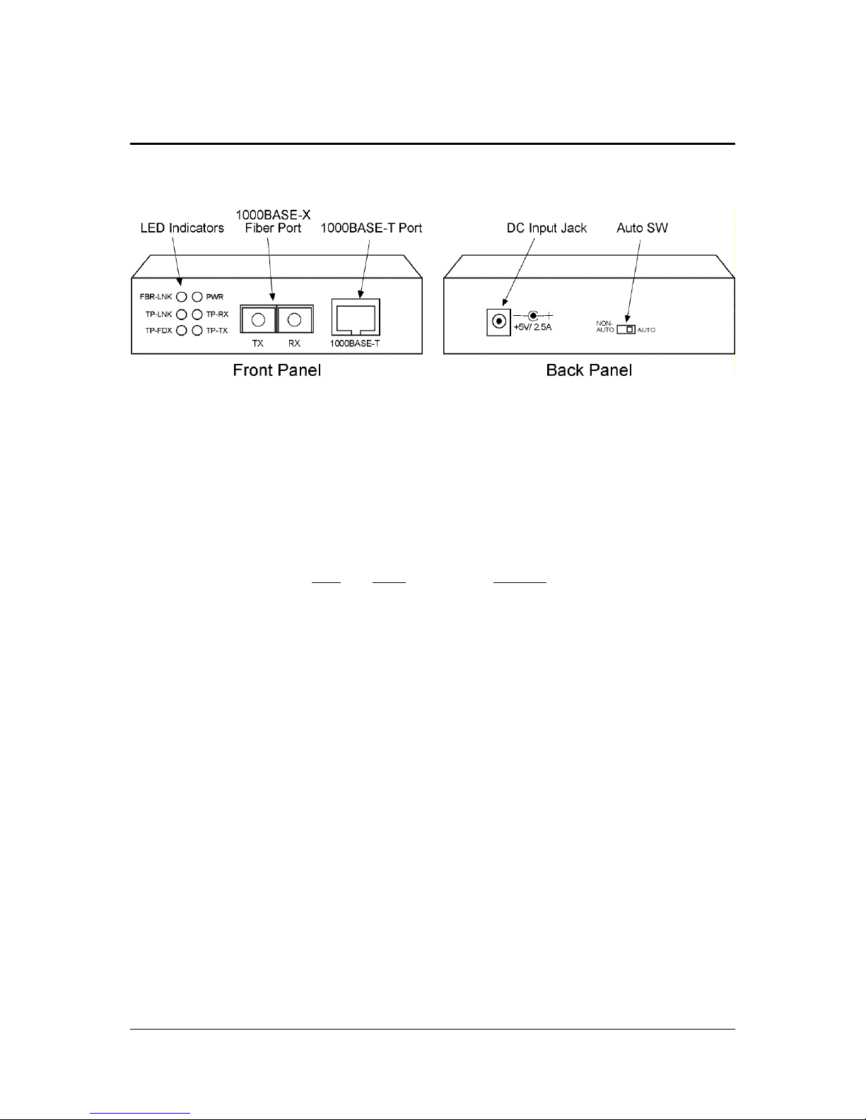
1. For connecting to early 1000BASE-X devices which do not provide
auto negotiation capability, you might need to set the SW to NON-
AUTO position to prevent unexpected link failure occurrence.
2. In most of the cases, setting AUTO would make the link worked.
3. When installing two of these converters on both ends of a fiber
connection, set the switch to NON-AUTO (forced full duplex mode)
to achieve the best performance.
Model Fiber Wavelength Outputpower InputSensitivity
210TF-SXC SX 850nm -9.5 ~ -4 dBm -12.5dBm max.
210TF-SXC-O SX 850nm -9.5 ~ -4 dBm -18dBm max.
210TF-LXC LX 1310nm -9.5 ~ -3 dBm -14.4dBm min.
210TF-LXC-O LX 1310nm -9 ~ -3 dBm -21dBm min.
210TF-LXC30-O LX 1310nm -5 ~ 0 dBm -24dBm min.
210TF-LXC40 LX 1550nm DFB -5 ~ 0 dBm -24 dBm max.
210TF-LXC80 LX 1550nm DFB -2 ~ 3 dBm -24 dBm max.
Model FiberUsed CableLength
210TF-SXC MMF 62.5/125 220 meters
MMF 50/125 500 meters
210TF-SXC-O MMF 62.5/125 300 meters
MMF 50/125 500 meters
210TF-LXC MMF 62.5/125 550 meters
MMF 50/125 550 meters MM: Multimode
SMF 9/125 10Km SM: Single mode
210TF-LXC-O SMF 9/125 10Km
210TF-LXC30-O SMF 9/125 30Km
210TF-LXC40 SMF 9/125 40 ~ 50Km
210TF-LXC80 SMF 9/125 80Km

-7-
2.2 LED Indicators
Name Status State Interpretation
PWR Power status On Power on
Off Power off
TP-LNK UTP link status On TP Link up
Off TP Link down
TP-FDX UTP duplex status On TP full-duplex
Off TP half-duplex
TP-RX UTP Rx status On TP Receiver in operation
Off TP no receiving operation
TP-TX UTP Tx status On TP Transmitter in operation
Off TP no transmission
FBR-LNK Fiber link status On Fiber link up
Off Fiber link down

-8-
2.3 Applying Power
The DC input of the converter is:
DCInputJack
DC input rated voltage +5VDC
DC input voltage range +4.75 ~ 5.25VDC
DC power consumption max. 0.8A @+5V (4 Watts)
DC input Jack
Before you begin the installation, check the AC voltage of your area. The
AC power adapter which is used to supply the DC power for the unit should
have the AC voltage matching the commercial power voltage in your area.
The specifications of the AC power adapter are:
• AC input power: AC power voltage of your area
• DC output power: +5V minimal 1.5A
Steps to apply power are:
1. Connect power adapter DC plug to the DC input jack located on the
back of the converter before connecting to the AC outlet.
2. Connect the power adapter to the AC outlet.
3. Check Power LED indication.

-9-
2.4 Making Connection
The figure below shows the configuration used when connecting to
auto-negotiation device and non-auto-negotiation device.
For proper communication, the UTP connections on both ends must be
in same configuration, either 1000M full-duplex or 1000M half-duplex. Set
Auto SW to NON-AUTO mode to use forced full duplex mode for fiber
connection.
This manual suits for next models
6
Table of contents
Other KTI Media Converter manuals
Popular Media Converter manuals by other brands

LEGRAND
LEGRAND VADDIO AV Bridge Nano installation guide

Panasonic
Panasonic AJUFC1800P - FORMAT CONVERTER operating instructions

FS
FS 10Base-T quick start guide

Paugge
Paugge ENT-SP20B16 user manual

Analytic Systems
Analytic Systems VTC305 Installation & operation manual

Autonics
Autonics E100 Series product manual