KTI KGC-352 Series User manual

-1-
PoE Powered
Gigabit Ethernet Media Converters
1000BASE-T TO 1000BASE-SX/LX
KGC-352 Series
InstallationGuide
DOC.070820-KGC-352

-2-
(C)2007KTINetworksInc.Allrightsreserved.No part of this documen-
tation may be reproduced in any form or by any means or used to make
any directive work (such as translation or transformation) without per-
missionfromKTINetworksInc.
KTI Networks Inc. reserves the right to revise this documentation and to
make changes in content from time to time without obligation on the part
of KTI Networks Inc. to provide notification of such revision or change.
For more information, contact:
UnitedStates KTINetworksInc.
P.O.BOX631008
Houston,Texas77263-1008
Phone: 713-2663891
Fax: 713-2663893
E-mail: [email protected]
URL: http://www.ktinet.com/
International Fax: 886-2-26983873
E-mail: [email protected]
URL: http://www.ktinet.com.tw/

-3-
The information contained in this document is subject to change without
prior notice.Copyright (C) All Rights Reserved.
TRADEMARKS
Ethernet is a registered trademark of Xerox Corp.
FCC NOTICE
This device complies with Class B Part 15 the FCC Rules. Operation is
subject to the following two conditions: (1) This device may not cause
harmful interference, and (2) this device must accept any interference
received including the interference that may cause.
CE NOTICE
Marking by the symbol indicates compliance of this equipment to
the EMC directive of the European Community. Such marking is indica-
tive that this equipment meets or exceeds the following technical stan-
dards:
EMC Class B
EN 50081-1/1992 : EN55022, EN61000-3-2, EN61000-3-3
EN 50082-1/1998 : EN61000-4-2, EN61000-4-3, EN61000-4-4, EN61000-4-5,
EN61000-4-6, EN61000-4-8, EN61000-4-11

-4-
Table of Contents
1. Introduction.........................................................5
1.1 Key Features ................................................................................. 6
1.2 Specifications ................................................................................ 7
1.3 Model Definition ............................................................................. 9
1.4 Optical Specifications.................................................................. 10
2. Installation......................................................... 11
2.1 Unpacking .....................................................................................11
2.2 Safety Cautions ............................................................................11
2.3 Mounting the Device .................................................................... 12
2.4 Powered by PoE over Cat.5......................................................... 13
2.5 Powered by External Power Adapter ........................................... 14
3.Applications ......................................................15
3.1 Extending Connection Distance .................................................. 15
3.2 Connecting to a Fiber Gigabit Ethernet Port ............................... 15

-5-
1. Introduction
The1000BASE-Tto1000BASE-SX/LXmediaconverterseriesprovides
1000MbpsGigabit Ethernet copper-to-fiber media conversion, allowing
for 1000Base-T-1000Base-X over multimode or optional single-mode fi-
beropticalmedia.
Because of 802.3af compliance, the converters can draw the power via
Cat.5 cable connected to a PoE PSE switch or mis-span injector in addi-
tion to being powered by typical external power adapter,. This feature
makes the converter ideal for remote areas of a network without AC
power outlets.

-6-
1.1 Key Features
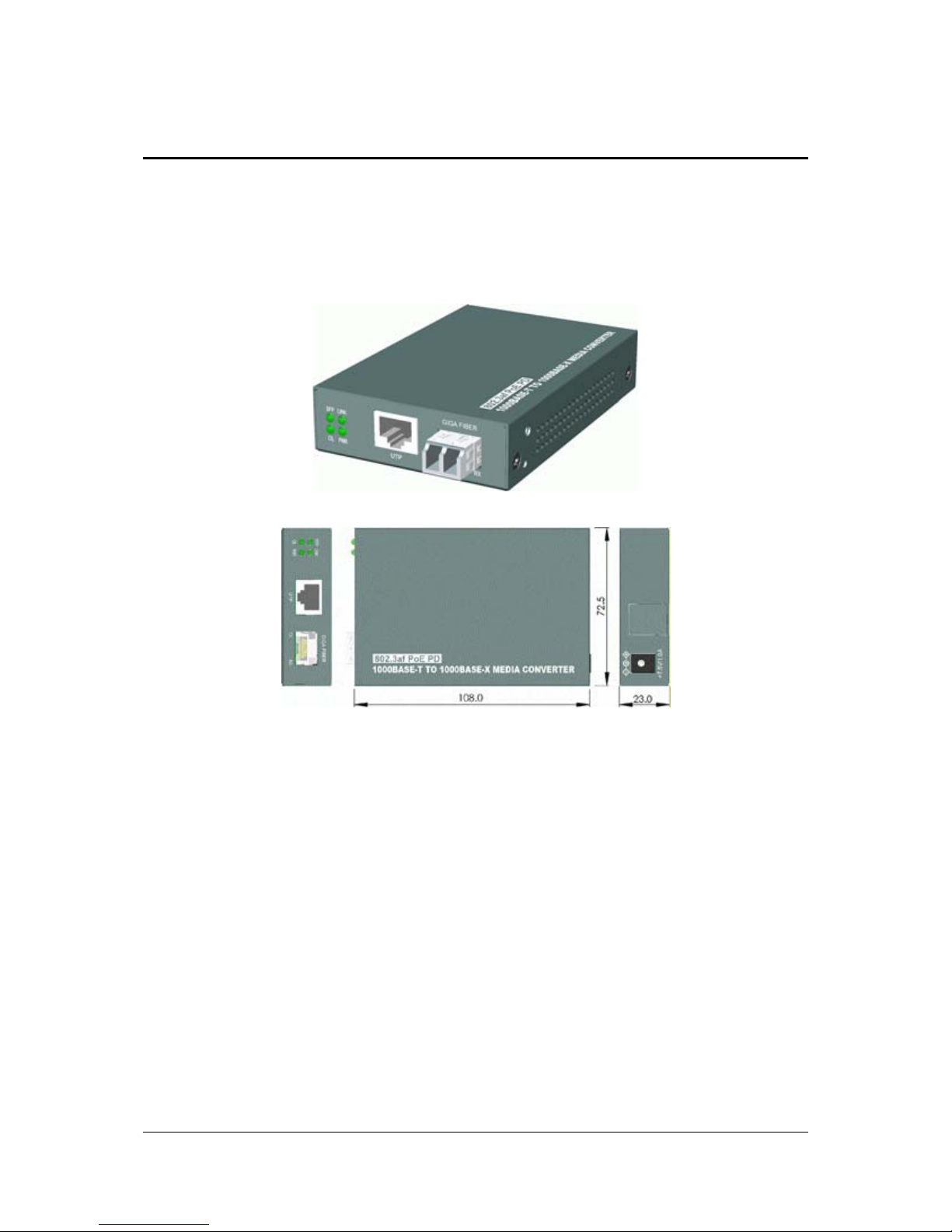
• Gigabit copper to fiber conversion: 1000Base-T-to-1000Base-SX/LX
overmultimodeorsingle-modefiber
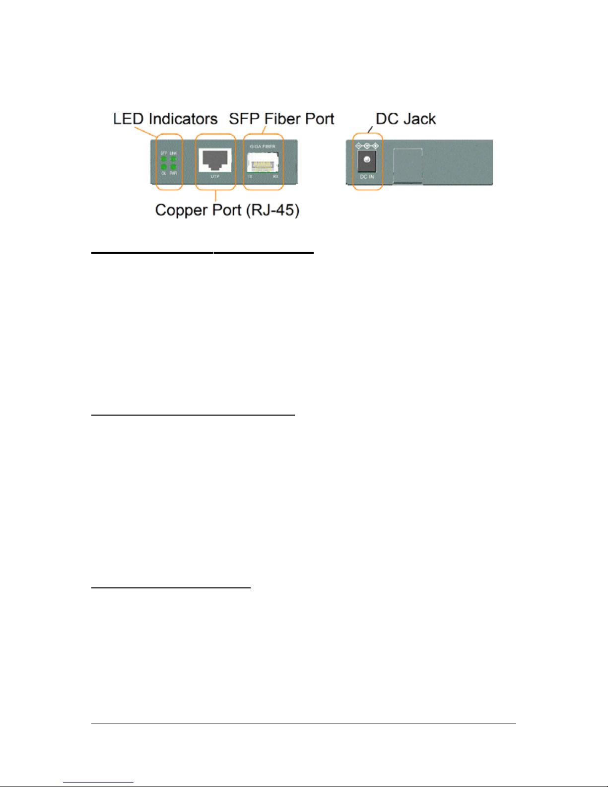
• SFPdesign:Forflexibility,anSFP(Mini-GBIC)connector isprovided
for the fiber port to accommodate any type of SFP fiber transceiver
when needed.
• Support full wire speed copper to fiber conversion
• Auto MDI/MDI-X detection function on the copper port
• Auto-negotiation support
• Plug and play : no configuration settings is required
• Link Fault Pass Through : this function allows link fault status passes
through between copper link and fiber link transparently.
• Far End Fault function on fiber port
• Transparent conversion to any type of packet frame
• No packet length limitation
• Diversified mounting support : desktop mounting, wall mounting,
optionalDin-Rail support
• Support wide range of fiber options : multimode fiber, single mode
fiber (short reach up to long reach), Bi-directional single fiber, and
CWDM optical
• Low power consumption
• IEEE802.3afcompliant PoE PD(PoweredDevice) design

-7-
1.2 Specifications
Twisted-PairInterface(CopperPort)
Connector ShieldedRJ-45
SignalCompliance IEEE802.3ab1000BASE-Tstd.
Pin Assignments Auto MDI/MDI-X detection
Data Speed 1000Mbps
Configuration Auto-negotiation support
Cable Types Category 5 or higher UTP
LinkDistance Up to 100 meters
FiberOpticInterface(FiberPort)
SignalCompliance IEEE802.3z1000BASE-SX/LXstd.
Connector SFPfor pluggable fiber transceiver
Data Speed 1000Mbps,full duplex
Cable Types MMF-50/125,62.5/125mm
SMF-9/125mm
LinkDistance MMF up to 500m
SMF -model dependent
Eye Safety compliance IEC825Class1
PoE(PoweroverEthernet)
Standard IEEE802.3afPD(PoweredDevice)
Power Reception TPport RJ-45Pin1,2,3,6 orPin 4,5,7,8
InputVoltage 36~57VDCviaCat.5
Power Classification Class 1

-8-
DCPowerInput
Interface DCJack(-D6.3mm/+D2.0mm)
OperatingVoltages DCinput+6.7V~+57V
Power consumption max2W@+7.5VDCinput
Power Supply Options ExternalAC-DC power adapters
Inputoptions:AC100V/120V/230V/240V
Ratedoutput:DC7.5V500mAmin.
Mechanical
Dimension (base) W108mmxD72.5mmxH23mm
Housing Enclosed metal with no fan
Weight 205g
LEDIndicators
PWR ON Power on
OFF Power off
SFP ON SFPtransceiver is installed.
OFF No SFPtransceiver is installed.
LINK ON Copper-fiberlink up
OFF Copper-fiber link down
BLINK Copper-fiber link with data traffic
OL ON Fiber port optical signal detected
OFF Fiber port no optical signal
Environmental
OperatingTemperature -5~55oC
StorageTemperature -40~85oC
RelativeHumidity 5%~90%
Approval
FCC Part 15 Class B
CE/EMC EMIEN50081-1ClassB,EMSEN55024
Safety IEC60950(CE/LVD)

-9-
1.3 ModelDefinition
ModelSeries:KGC-352-X
Duplexfiber
XFiberCon. FiberDistance(Typ.)
none FreeSFP no SFP transceiver
SX LC DuplexMMF500m
LX LC DuplexMMF550m,SMF10km
LX20 LC DuplexSMF20km
LX30 LC DuplexSMF30km
LX50 LC DuplexSMF50km
LX70 LC DuplexSMF70km
Bi-directionalWDMoversingleSMF
W3510 LC SimplexSMF10km
W5310 LC SimplexSMF10km
W3520 LC SimplexSMF20km
W5320 LC SimplexSMF20km
W3410 LC SimplexSMF10km
W4310 LC SimplexSMF10km
W3410S SC SimplexSMF10km
W4310S SC SimplexSMF10km
Allmodels listed belowexcept Model 300 areshipped with apre-installed
SFPfiber transceiver.

-10-
1.4 Optical Specifications
ModelSeries:KGC-352-X
DuplexFiber Series
X Wavelength TxPower*1RxSen.*2Max.Rx*3
SX 850nm -9.5~-4 -18 -1
LX 1310nm -9.5~-3 -20 -3
LX20 1310nm -7~0 -24 -3
LX30 1310nm -4~+3 -23 -3
LX50 1550nm -4~+1 -23 -3
LX70 1550nm 0~ +5 -23 -3
Bi-DirectionWDMoversingleSMF
W3510 T1310/R1550 -9~-3 -21 -3
W5310 T1550/R1310 -9~-3 -21 -3
W3520 T1310/R1550 -8~-3 -23 -3
W5320 T1550/R1310 -8~-3 -23 -3
W3410 T1310/R1550 -9~-3 -20 -3
W4310 T1550/R1310 -9~-3 -20 -3
W3410S T1310/R1550 -9~-3 -20 -3
W4310S T1550/R1310 -9~-3 -20 -3
*1TxPower:Transmitter power(min. ~ max., unit:dBm)
*2Rx Sen. : Receiver sensitivity (unit :dBm)
*3Max.Rx.: MaximalReceived power(unit :dBm)

-11-
2. Installation
2.1 Unpacking
Check that the following components have been included:
• Installation guide (or contained in the product CD)
• The Media Converter
Ifany itemis found missing or damaged,please contact your local reseller
forreplacement.
2.2 Safety Cautions
To reduce the risk of bodily injury, electrical shock, fire, and damage to
the product, observe the following precautions.
• Do not service any product except as explained in your system docu-
mentation.
• Opening or removing covers may expose you to electrical shock.
• Only a trained service technician should service components inside
these compartments.
• If any of the following conditions occur, unplug the product from the
electrical outlet and replace the part or contact your trained service
provider:
- The power cable, extension cable, or plug is damaged.
- An object has fallen into the product.
- The product has been exposed to water.
- The product has been dropped or damaged.
- The product does not operate correctly when you follow
the operating instructions.
• Do not push any objects into the openings of your system. Doing so
can cause fire or electric shock by shorting out interior components.
• Operate the product only from the type of external power source
indicated on the electrical ratings label. If you are not sure of the type
ofpower source required, consultyour service provider orlocal power
company.

-12-
2.3 Mounting the Device
DesktopMounting
The media converter can be mounted on a desktop or shelf. Make sure
that there is proper heat dissipation from and adequate ventilation around
the device. Do not place heavy objects on the device.
WallMounting
The media converter also can be mounted on a wall. On bottom of the
device, wall mounting hole is provided for wall mounting.
Din-railMounting
For a Din-Rail chassis, the media converter can support mounting on a
Din-Rail.An optionalDin-Rail bracket, KC-3DR can be purchased sepa-
rately. Consult your dealer for details. The following figures show an
exampleafter bracket installation:

-13-
2.4 Powered by PoE over Cat.5
PowersupplybyaMid-SpanPoEInjector
The following figure illustrates the converter is powered by the PoE
delivered from a remote mid-span PoE injector over Cat.5.
PowersupplybyaPoEPSESwitchedPort
The following figure illustrates the converter is powered by the PoE
deliveredfrom a remote PoE PSE switch over Cat.5.
Note:
1. The Cat.5 used can be the standard Cat.5 cable for Ethernet connec-
tion.
2. Check the power LED on the converter to see whether the power is
received on the Cat.5.
3.For the compatibility, the remotePoE PSE used must be IEEE 802.3af
compliant.

-14-
2.5 Powered by External Power Adapter
The converter can support being powered by an external power adapter as
an alternative when PoE power is not available on Cat.5. Before you begin
the installation, check theAC voltage of your area. TheAC power adapter
which is used to supply the DC power for the unit should have the AC
voltage matching the commercial power voltage in your area.
TheACPowerAdapterSpecifications
AC input power: AC power voltage of your area,
Rated input options -
AC120V/60Hz,AC230V/50Hz,
AC100V/50-60Hz,RatedAC240V/50Hz
Ratedoutput-DC7.5V500mAmin.
Steps to apply the power to the converters are:
1. Connect power adapterDC plug to theDC input jack located on the
back of the converter before connecting to the AC outlet.
2. To ensure against accidental disconnection, tie the DC cable with the
cable tie located the back of the converter.
3. Connect the power adapter to the AC outlet.
4.CheckPower LEDindication.

-15-
3. Applications
3.1 Extending Connection Distance
Use two media converters connected with an appropriate fiber cable to
extend the connection distance between two Gigabit copper devices as
shown below:
3.2 Connecting to a Fiber Gigabit Ethernet Port
The converter can also connect to a remote fiber Gigabit Ethernet port
over a fiber cable. It extends the connection distance between a copper
port and a fiber port as shown below:
Table of contents
Other KTI Media Converter manuals